Learn about 2-wire discrete DC sensors and how to connect them to a PLC input card


In this blog post and video, you will learn how to wire a 2-wire DC sensor, like a switch or a contact, to a PLC input card. You will also learn what a 2-Wire Discrete sensor is and recognize some of the common types of 2-Wire Discrete sensors.
DC sensors can be used to indicate the state of a device or a process to the PLC program. Knowing these input states can allow the PLC program to make decisions, such as, when to start or stop a pump.
In this diagram, the Programmable Logic Controller, or PLC, is running a ladder logic program. The pushbutton is connected to a PLC input card, and the logic program is written to sense the state of the pushbutton. When the pushbutton is not pressed, the logic does not turn the pump on.
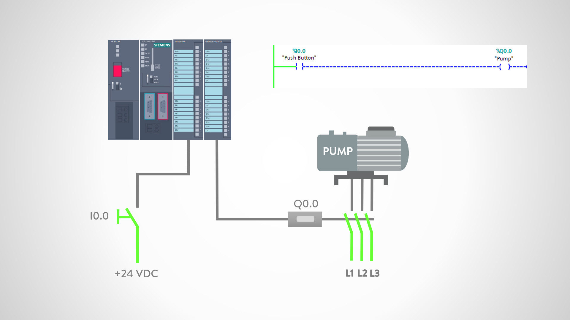
Now, if the pushbutton is depressed, the PLC ladder logic program will sense that the pushbutton has been pressed, and will start the pump.

So, let’s see how we can make this important input information available to a PLC program. In order to do this, we need to understand more about these discrete sensors and how they are wired to the PLC.
Discrete DC Sensors, or discrete Direct Current sensors, operate in a circuit with a battery or other power source, commonly known as a power supply. A power supply is placed in an electrical circuit to provide power to the connected devices, like a switch, or a lamp.
DC power supplies are referred to by their voltage and capacity, indicated by how many amperes they can supply. The more amperes a power supply can deliver, the larger and more expensive they generally are.

In DC PLC circuits, the power supply almost always supplies 24 Volts DC to the connected devices. In the diagram below, a DC circuit is shown which turns on a lamp when a pushbutton is pressed. The common trait of all discrete DC sensors is that they have exactly two operating states, “on” and “off”.

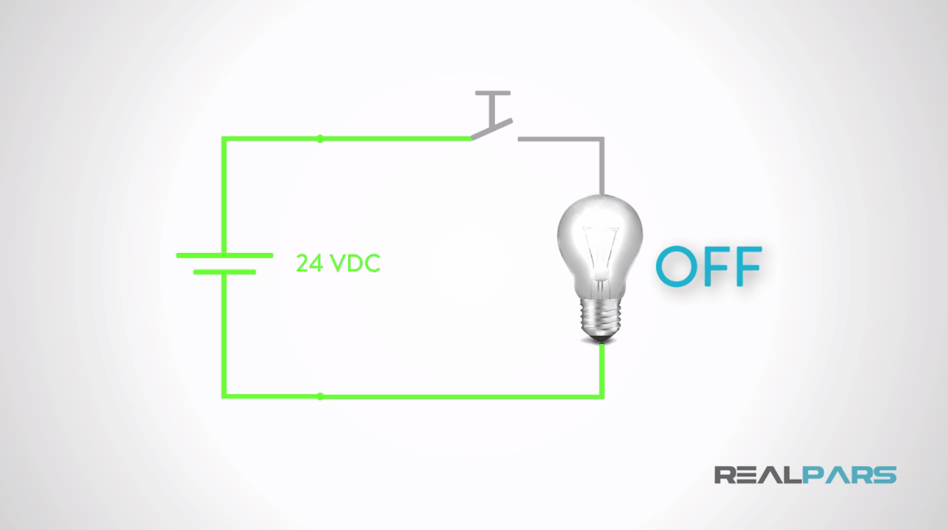
A discrete DC pushbutton, as in this diagram, is “on” when it is pressed and its internal contact is “closed”, forming a complete circuit and allowing the flow of electrons.
When the pushbutton is released, its contacts are “opened” again, the circuit is broken, and the flow of electrons stops. The state of the pushbutton is “off”.
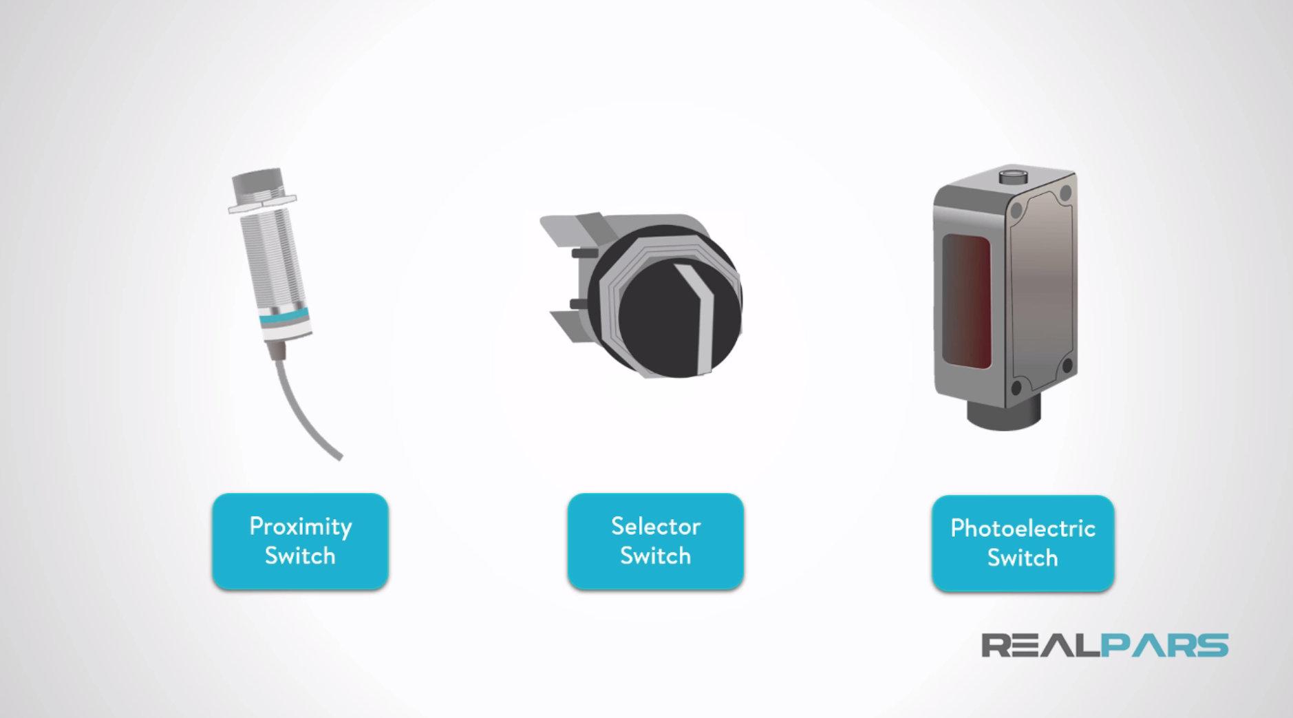
Other common examples of discrete DC sensors include proximity switches, selector switches, and photoelectric sensors.
If we want to monitor the state of the pushbutton in the PLC, we would need to connect the two wires of the pushbutton to a digital input card in the PLC. When the pushbutton is not pressed, the PLC would see the input state as “off”, or a 0. The circuit to/from the PLC input is “open” or not energized.

When the button is pressed, the PLC input senses the change in pushbutton state, and transmits this data through a communication channel to the processor memory, or data table. When the pushbutton is pressed, the circuit to/from the PLC input is “closed” or energized.
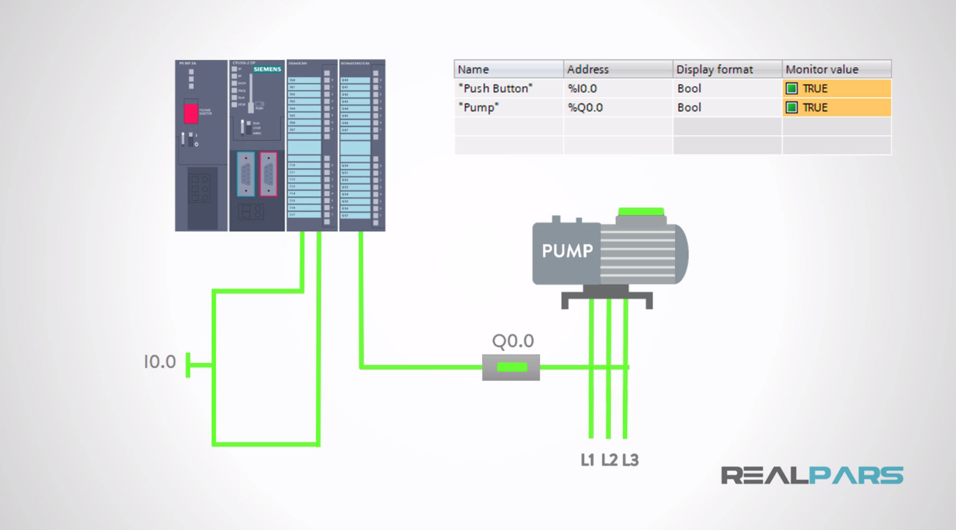
We could then write a PLC program, which resides in the memory of the PLC, to take some action, like turning on a lamp or a pump, when the pushbutton is pressed.
Wiring a discrete DC sensor to a PLC input card is easy and straightforward. In this article, we will consider only devices that have two wires that need to be connected to the PLC digital input card. An example, a Hall-Effect proximity switch, is shown here. In a separate article, we will consider more complex “three-wire” devices.

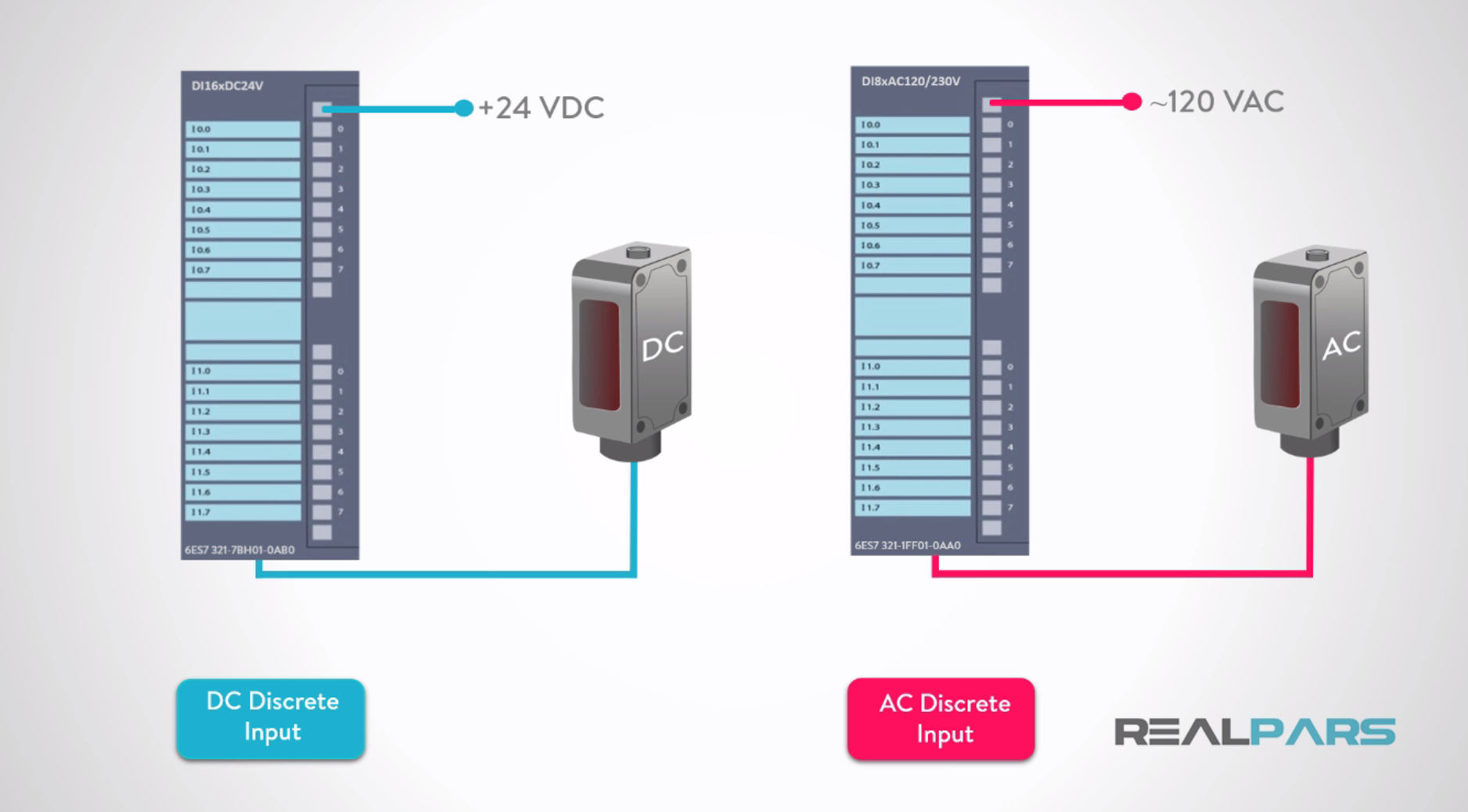
For most PLC’s, the input cards must match the type of circuit that will be employed to interface the device to the PLC. For example, a discrete DC device must be wired to a discrete DC input card. A discrete AC device would require a discrete AC input card. In this article, we will consider only DC devices.
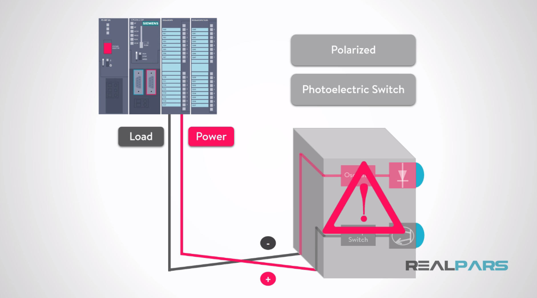
In order to connect a “two-wire” discrete DC device to the PLC, we will need to identify whether the device is “polarized” or “non-polarized”. For a “polarized” device, the two wires will be labelled: one wire is labelled “positive” and one wire is labelled “negative”.
In the simplified diagram of a photoelectric switch below, the “positive” wire must be connected to the “positive” terminal of the PLC input, and the “negative” wire must be connected to the “negative” terminal of the PLC input.

If this convention is not followed, the device will not indicate correctly in the PLC, and the device may be damaged. For this photoelectric switch, reversing the “positive” and “negative” wires will damage the phototransistor and there will be no power to the transmitter. The switch will not function as intended.
For “non-polarized” devices, like simple pushbuttons and selector switches, the device may be wired with either wire connected to the positive terminal of the PLC card, and the other wire connected to the negative terminal of the PLC card.
In the diagram below, the proximity switch is a non-polarized device. It has two wires, a white wire, and a black wire. On the left, the white wire is connected to the positive terminal of the digital input channel and the black wire is connected to the negative terminal.
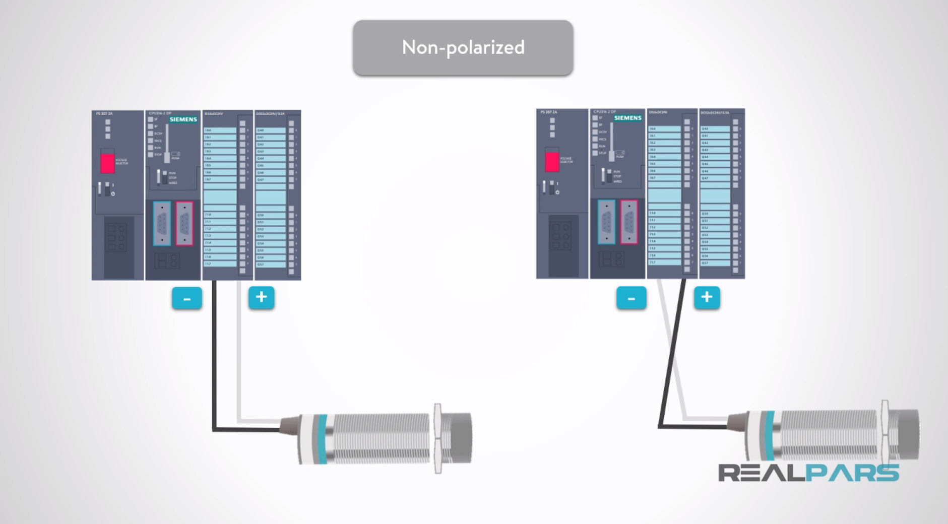
Because the device is non-polarized, the wires could be connected in the opposite configuration and still provide the correct indication of its state in the PLC. This is depicted in the drawing on the right.
Now, let’s see how 2-wire discrete DC sensors are connected to actual PLC I/O cards.
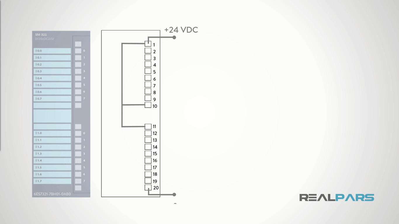
This is a schematic of a Siemens SM321 digital input card, part number 6ES7321-7BH01-0AB0. It is a 16-channel 24VDC digital input card that is very popular in Siemens PCS7 and S7-300 PLC systems. This digital input card wiring scheme is similar to most digital input cards used in the process industries.
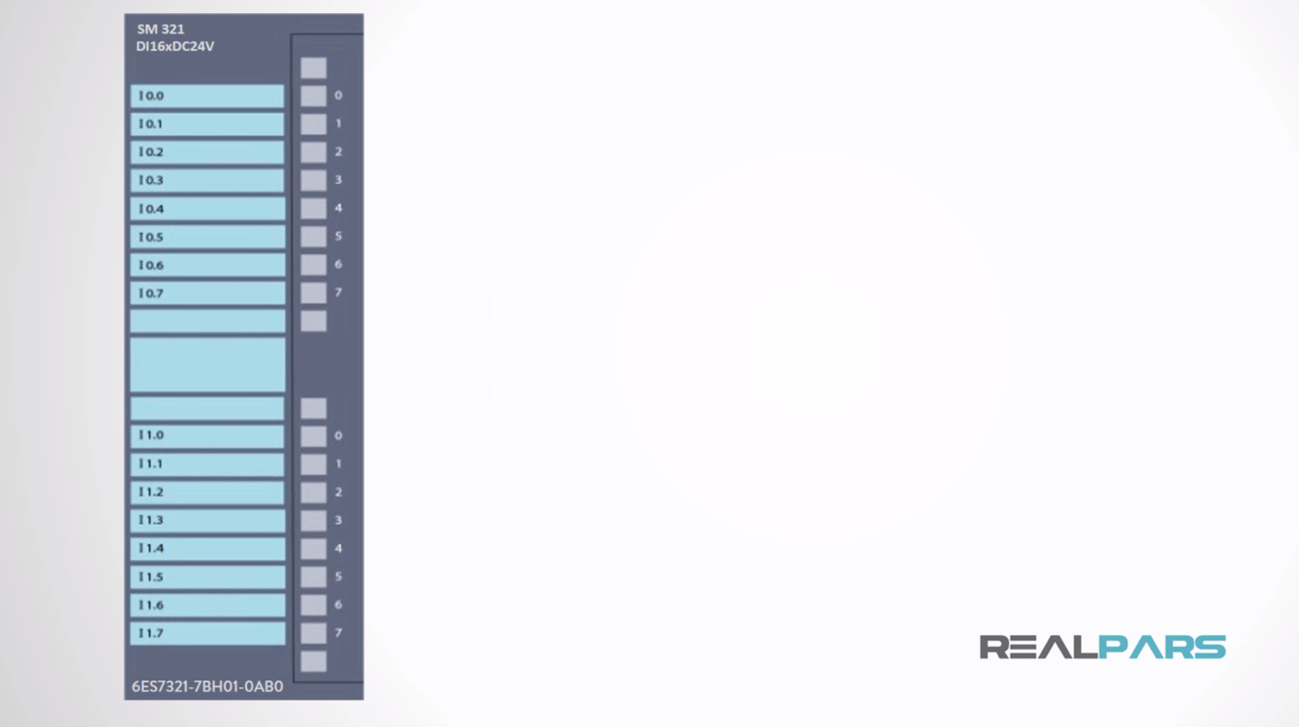
The SM321 has twenty screw terminals to which the digital inputs are connected. As we saw previously, for 2-wire discrete DC sensors, each digital input requires the connection of two wires.
The SM321 card requires 24VDC power to perform several functions. First, the card itself requires power to light the status LED’s, perform diagnostics, and to communicate the card’s input statuses back to the PLC.
Power to the card is supplied by a 24VDC power supply connected to terminals 1 and 20.

Internally inside the SM321 card, this same 24VDC power is connected to terminals 10 and 11. The power at terminal 10 supplies power for the top group of eight digital inputs, and the power at terminal 11 supplies power for the bottom group of eight digital inputs.
Let’s just focus on the top eight inputs, labelled as Input 0 through Input 7. In practice, the PLC input card channel connections, terminals 2 – 9 and 12 – 19, will be brought out to a terminal block. These marshalling connections, as they are called, allow the field wires to be more easily terminated in the control panel.
These terminals are represented by the letters A – H in this diagram. The installer usually “pre-wires” the marshalling terminals, terminal 2 on the SM321 card to terminal A, terminal 3 to terminal B, and so on.

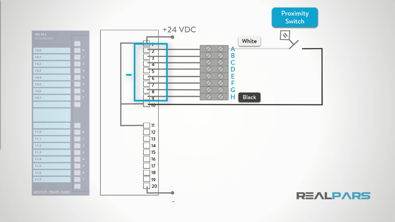
Now, let’s connect the proximity switch and the photoelectric switch from the previous examples to the SM321 card. The eight marshalling terminals A-H, are wired to Channels 0 – 7, and are the negative terminals in our discrete circuits.
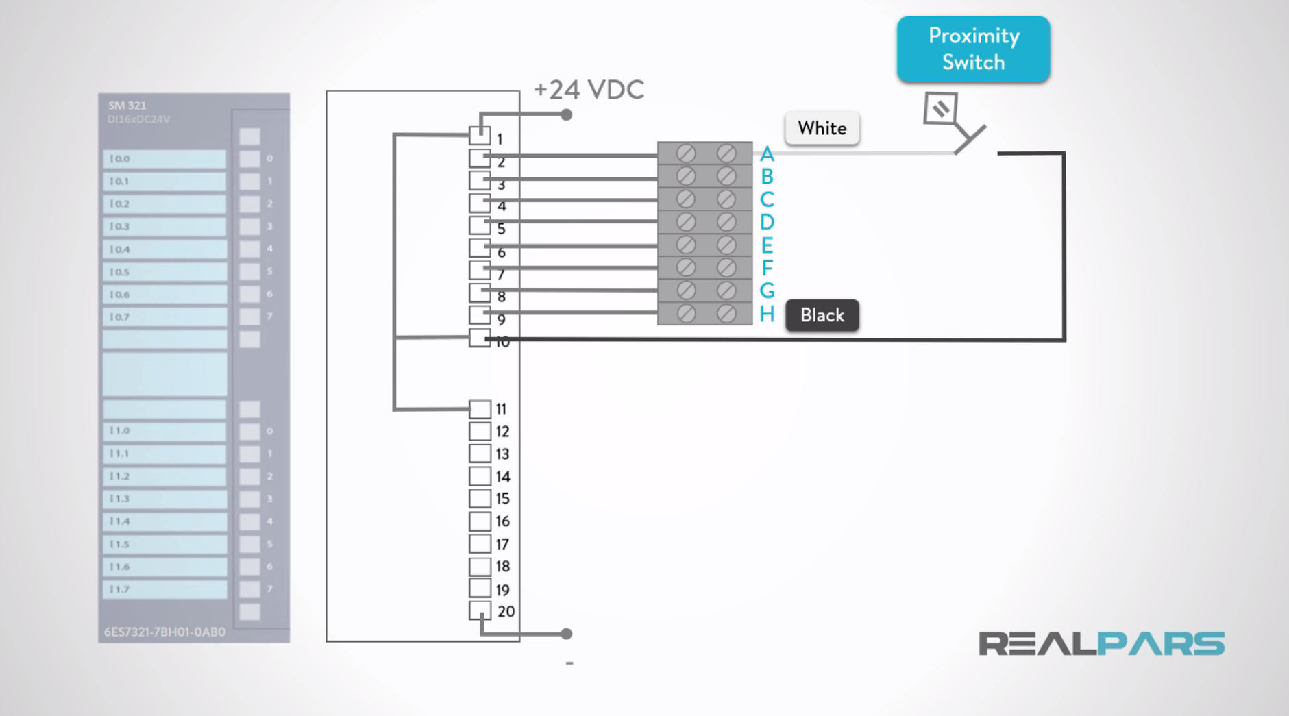
+24VDC will be obtained from terminal 10 for the top 8 inputs wired to the SM321 card and from terminal 11 for the bottom 8 inputs wired to the SM321 card.
Since the pushbutton is a non-polarized 2-wire discrete device, we can connect either its white or black wire to +24VDC, and the opposite wire to terminal A.

For a polarized device, like the photoelectric sensor, care must be taken to connect the positive wire (red wire) to +24VDC and the black wire to the negative terminal (PLC input card connection). If we connect the photoelectric switch to PLC input channel 3, the red wire will be connected to +24VDC, and the black wire will be connected to terminal D.

To review, we have learned that there are many types of discrete 2-wire DC sensors that can be wired to a PLC input.
Some devices are polarized, and some are non-polarized. For polarized devices it is important to connect the positive wire to the power, or positive terminal, of the PLC input and to connect the negative wire, or common, to the negative terminal of the PLC input.
For non-polarized devices, either wire can be connected to the positive terminal, with the opposite wire connected to the negative terminal.
A schematic of your specific DC digital PLC input card is required to determine how your specific device should be wired. The terminals connected to +24VDC are the positive terminals. In this example, the PLC input card terminals are the negative terminals.
Thank you so much for taking part of your day to be here. Leave a comment to let us know what you think and make sure to subscribe to our newsletter to get the latest content first.
The RealPars Team
With endless love and support,

Learn from
industry experts
with a free 7-day trial, then $25/month