How to Control a VFD with a PLC - Part 2 (HMS Anybus and Siemens Robicon)

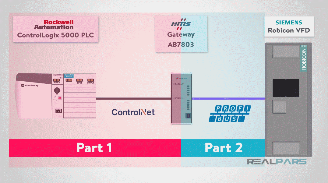
Welcome to Part 2 of Rockwell ControlLogix PLC and Siemens VFD Communication where you are going to learn how to how to configure the communication between HMS Anybus gateway and Siemens Robicon VFD.
As you have learned in the previous lesson, automation often requires communication between two heterogeneous systems from different manufacturers.
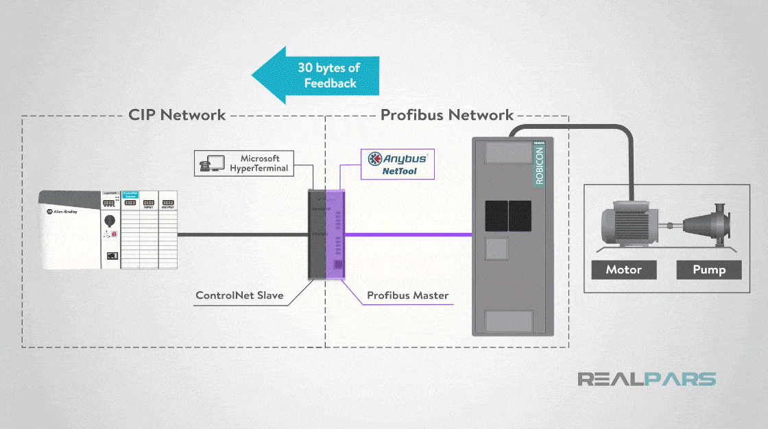
In this series of lessons, overall, we are communicating from a Rockwell Automation ControlLogix 5000 PLC using ControlNet network media with CIP protocol to a Siemens Robicon VFD using Profibus protocol, through HMS Anybus gateway converting ControlNet CIP protocol to Siemens Profibus protocol.
Introduction
As a prerequisite, please checkout Part 1 of this series, addressing how the communication between ControlLogix 5000 PLC and the HMS Anybus gateway is configured.
In part 2, this article, we are going to discuss how the HMS Anybus PROFIBUS Master gateway is configured to communicate with the Siemens Robicon VFD.
Finally, the third and last part, will address the Siemens Robicon PROFIBUS slave configuration.
An Overview of Profibus Master (Gateway) Configuration
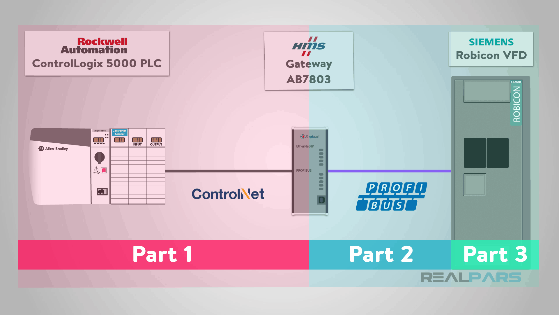
The ControlLogix PLC will be controlling a pump with a simple ON/OFF command and velocity by setting a speed setpoint to the VFD.
In response the Siemens VFD will return the actual speed reference and VFD status information controlling the pump.
This exchange of control data and status information is all performed by the HMS Anybus gateway. The HMS Anybus Gateway also performs an important responsibility as PROFIBUS Master controlling the Pump VFD.
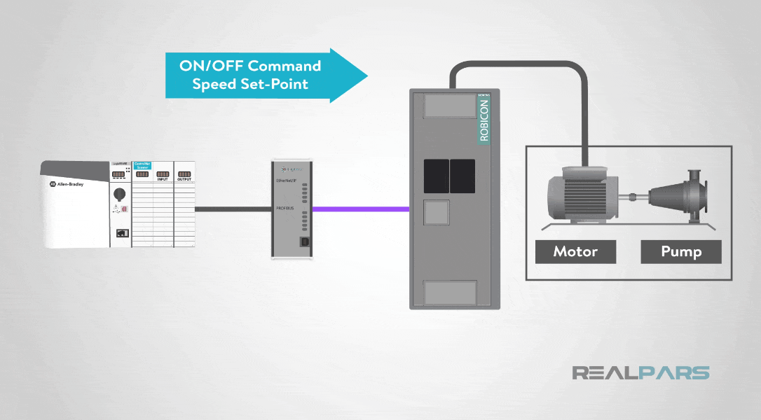
First, let’s review what the PROFIBUS master is responsible for.
The PROFIBUS master controls the entire communication dialog with the salves on the network.
The master writes and reads data from each slave one at a time. Each slave is required to respond to the request within a predetermined timeframe or the master will report a communication error.
Configuring the PROFIBUS Master in the gateway is accomplished by using HMS NetTool software.
The HMS PROFIBUS configuration is set to use:
– 30 bytes of input for real I/O data and status data for ControlLogix PLC
– 6 bytes of output to be controlled by the ControlLogix PLC
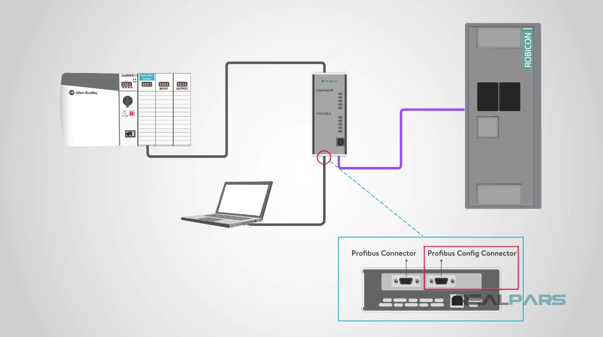
Using a null modem cable, we will connect to the COM port on a laptop and the COM port on the Gateway marked “PROFIBUS Config Connector”.
Profibus Master Configuration Using Anybus NetTool Software
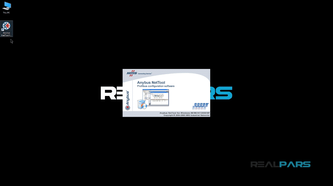
I will start up Anybus NetTool for PROFIBUS software by double-clicking on its Desktop icon.
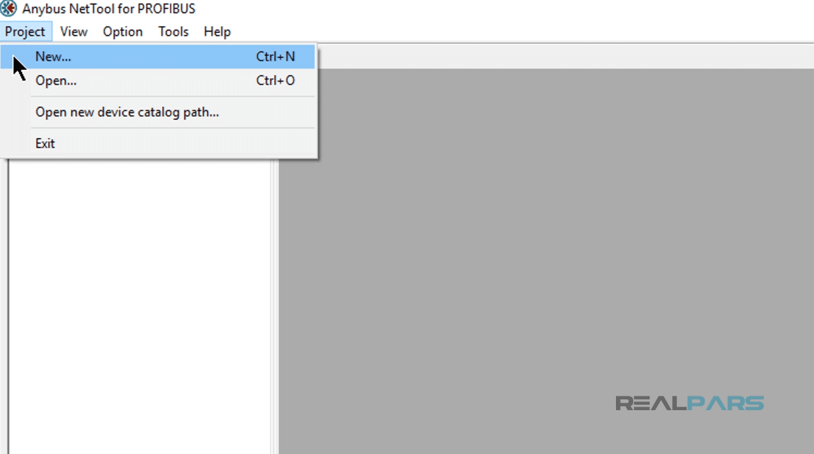
Next, select “New” from the NetTool “Project” Menu.
NetTool will display the “bus configuration user interface” window and the “available GSD file” window.
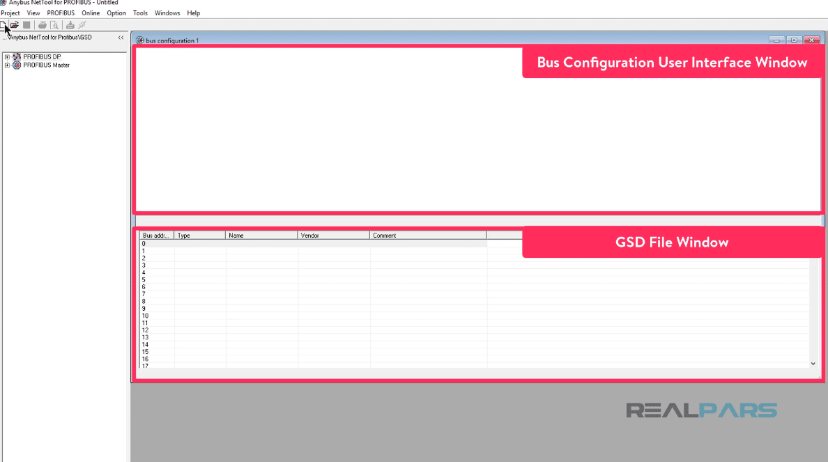
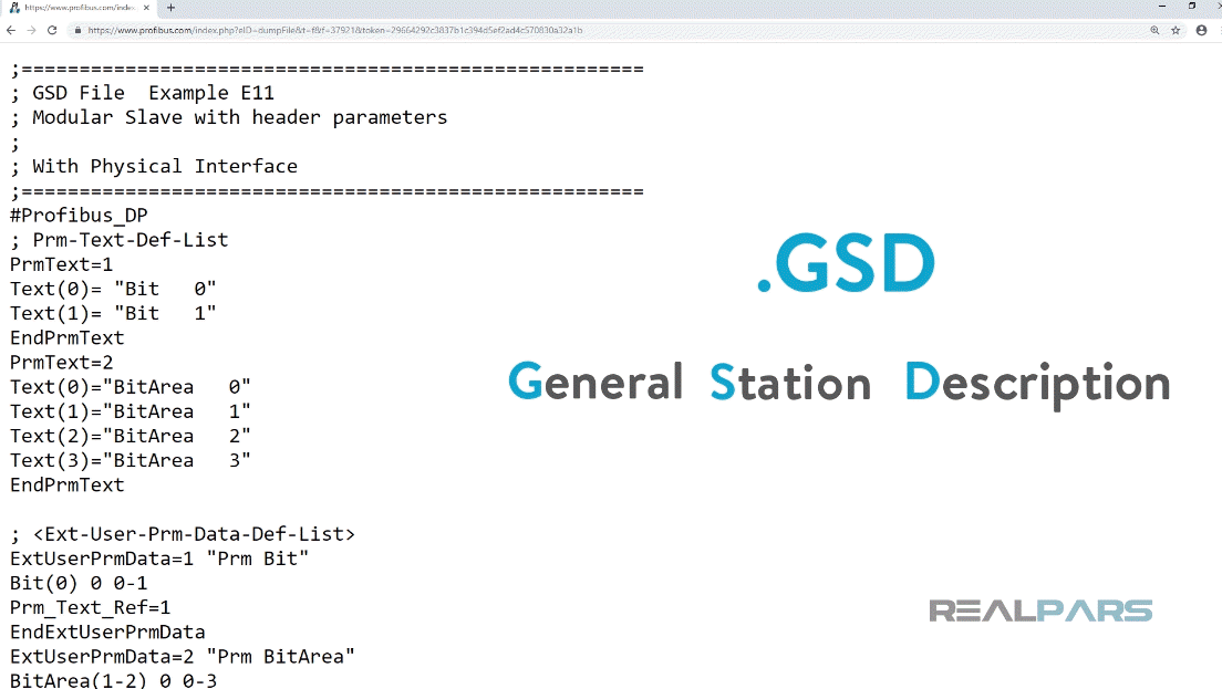
The GSD file or “General Station Description”, which is provided by the device manufacturer, contains a description of the PROFIBUS master or slave device.
GSD files provide a way for an open configuration tool to automatically get the device characteristics.
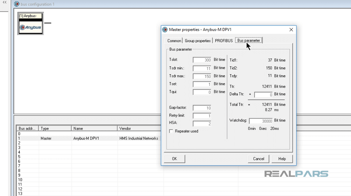
Next, we will select the Anybus-M DPV1 master GSD icon from the GSD user interface window and drag and drop it to the new configuration.
Now our bus configuration contains the Anybus-M Master icon. The address of the master has been set to 1.
By double-clicking on the Master icon and then selecting “bus parameter” tab, you can see that the Master bus properties are preconfigured, but may be changed by the User. I can Verify this window by pressing “OK”.
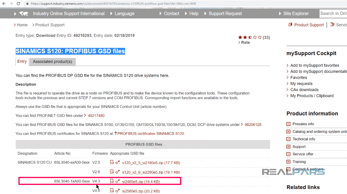
Next, we will add the Siemens SINAMICS S120/S150 GSD file, which we will download it from the Siemens website.
Go over to this page and download Siemens SINAMICS S120 PROFIBUS GSD file, called “si2480e5” version 4.3.
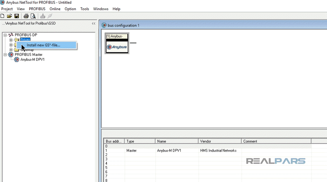
In the software environment, under the “PROFIBUS DP”, right click over the “Drives” and select “Install new GS file”.
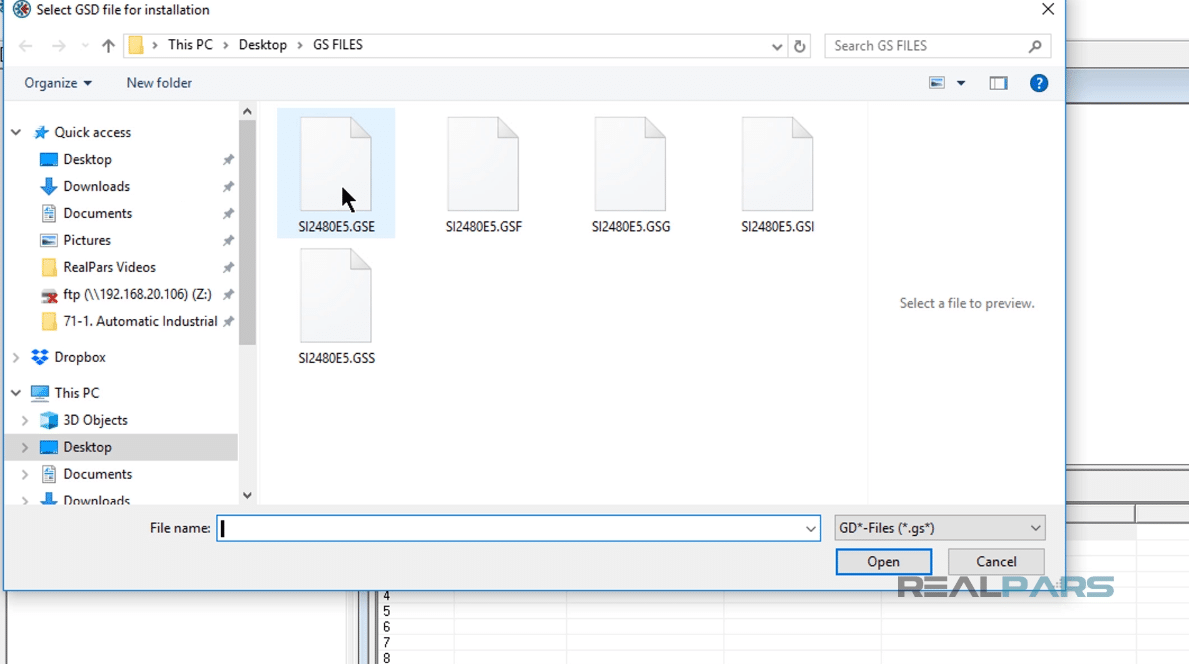
Browse to the location where your file is located. After you find it, double click on GSE file.
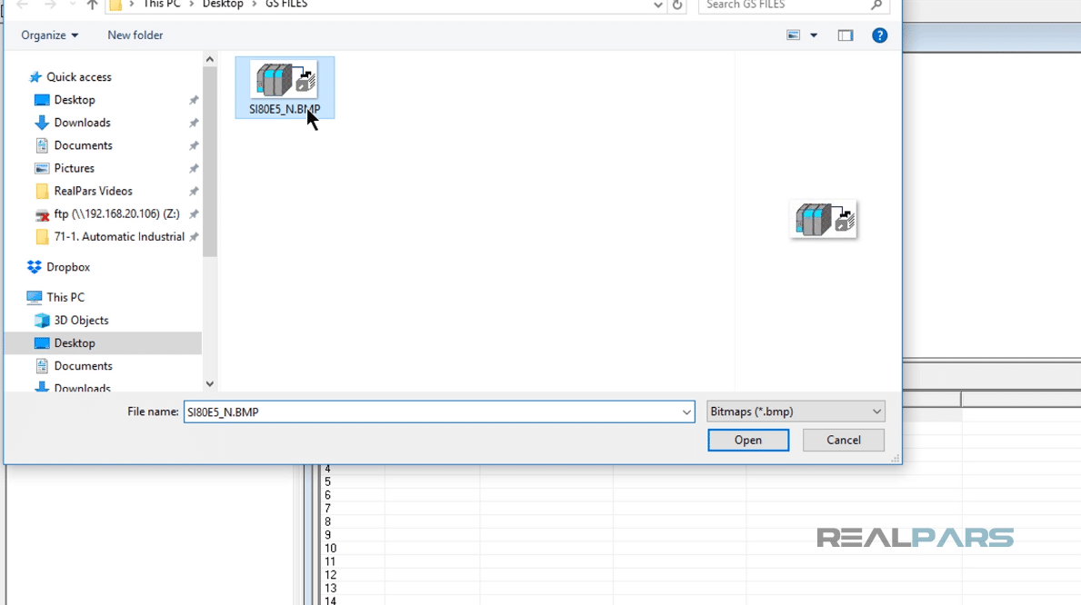
If your file contains any picture, in the opening window, click on “yes” and add the picture to the software by double-clicking on it.
Select the “SINAMICS S120/S150” and drag and drop it to the configuration.
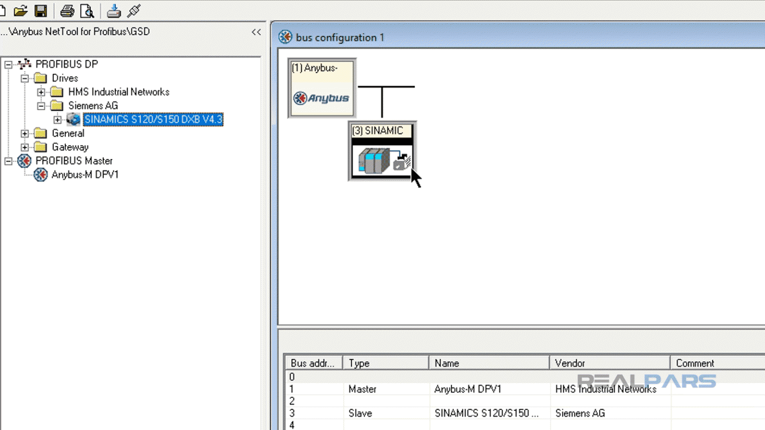
When we double click on “SINAMICS S120/S150” icon, the property window for the slave device will become available and we will primarily set the slave address to 3.
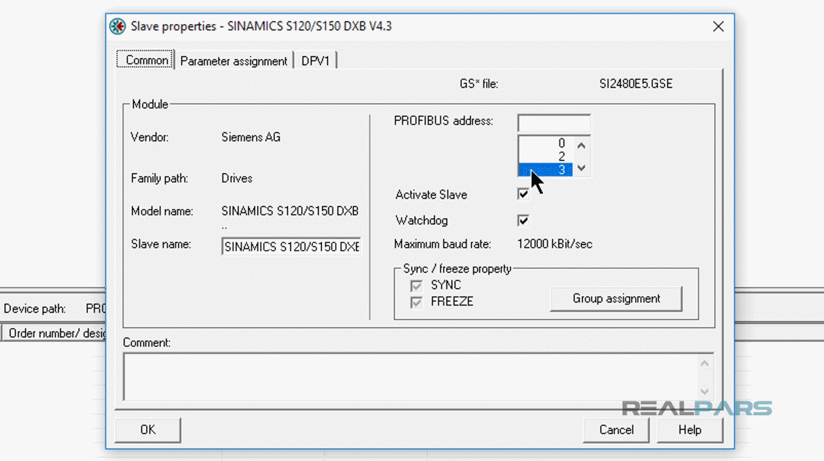
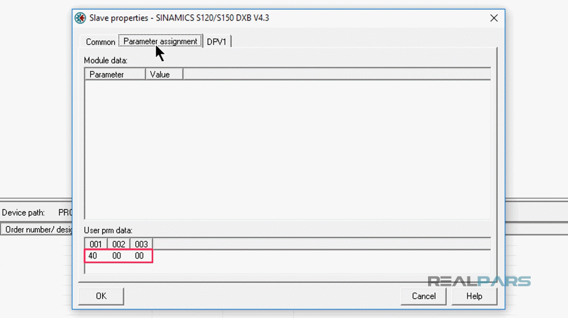
Under “Parameter assignment” tab we will be using the HEX values of 40 00 00. I will verify the “Slave properties” window by pressing “OK”.
With the PROFIBUS Master and Slave now configured we can go online with the Master to examine real-time data of the Slave.
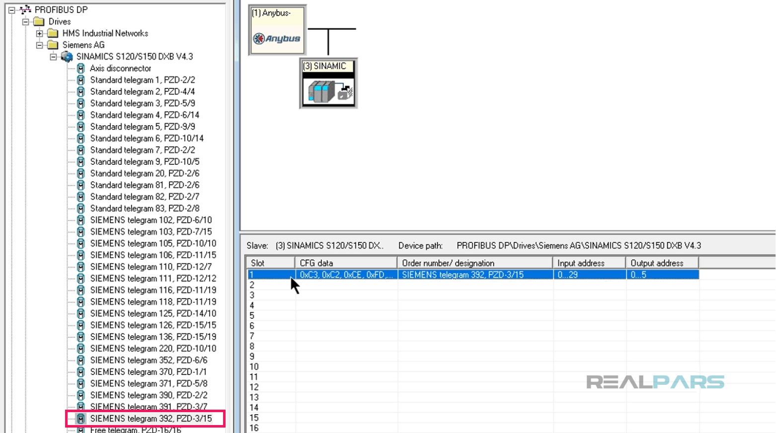
Configure the amount of I/O data for the Siemens VFD by extending SINAMICS S120/S150 and add “SIEMENS TELEGRAM 392” to slot 1 in the GSD file window.
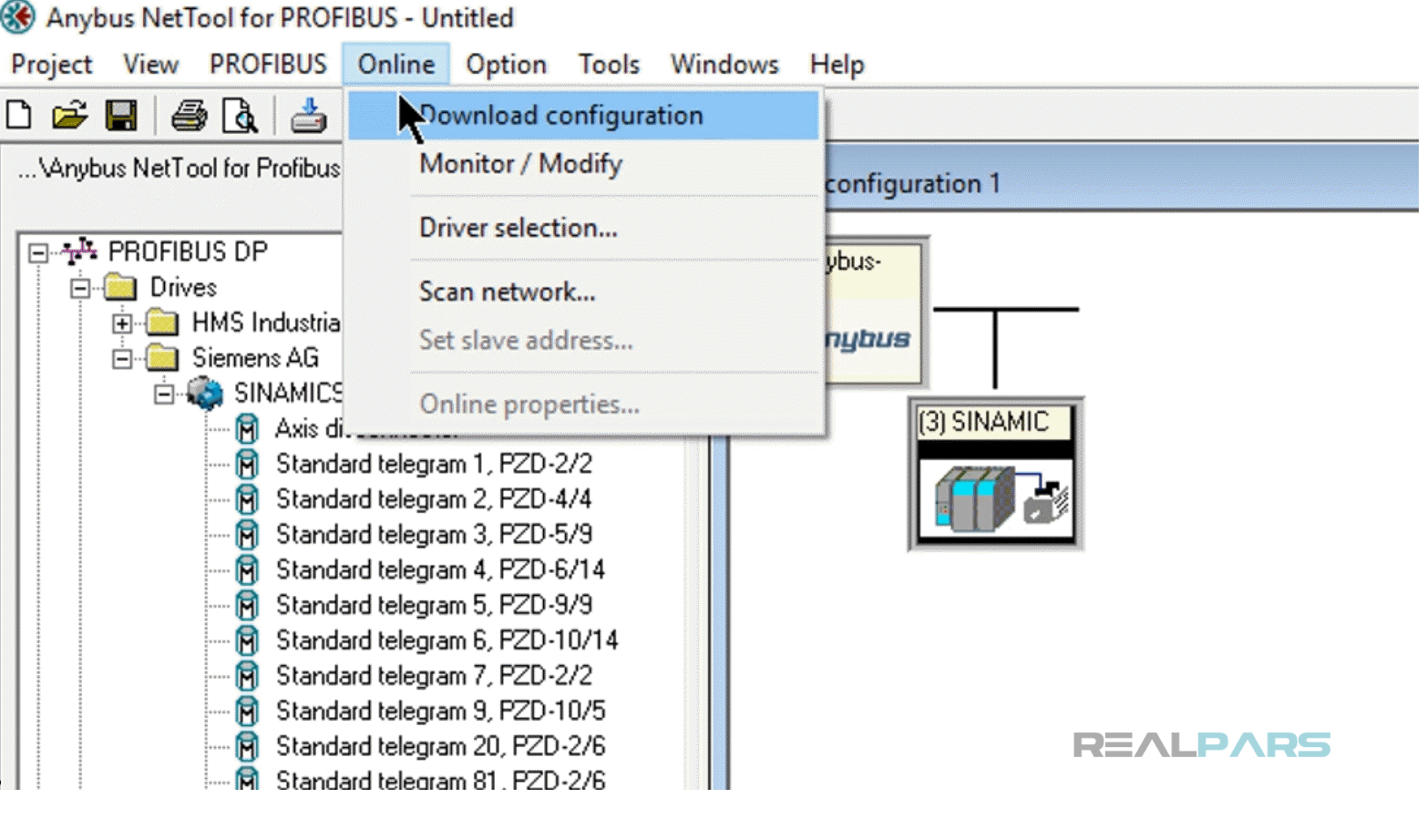
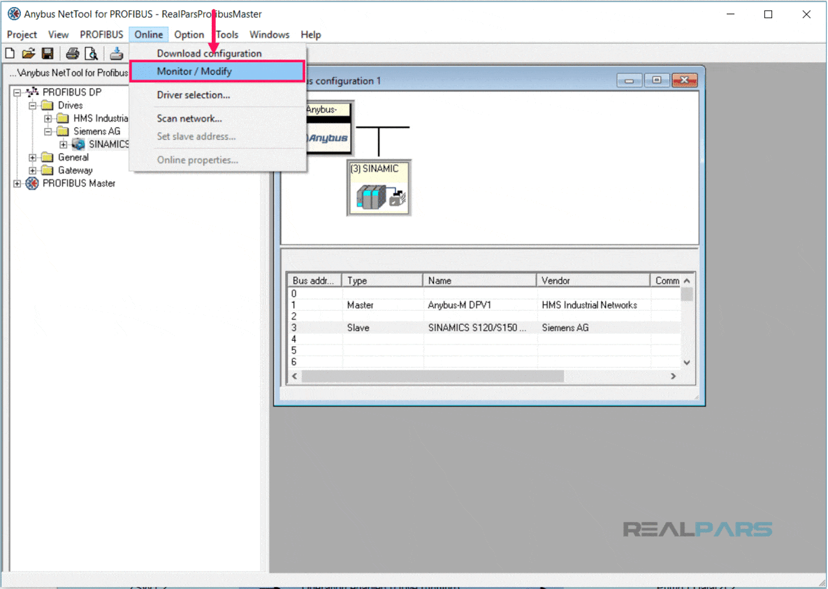
Next, we will download the NetTool configuration file to the HMS Master gateway.
To do so we will select “Online” from the NetTool menu and then choose “Download Configuration”.
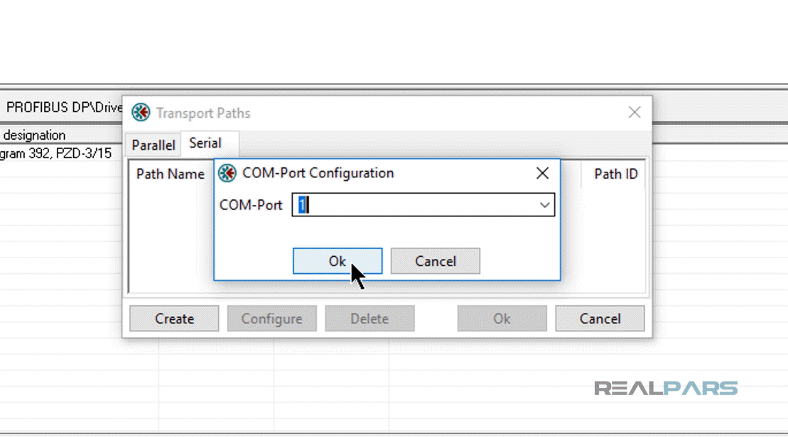
In the opening window, select “Serial” tab and then click on “Create” button.
Select “COM-Port Transport Provider” and then hit “OK”.
Supply a name for the new path and press “OK”.
In this configuration window, enter the serial COM-port as mentioned in the previous video.
To finish the transport path configuration, I will click on “OK”.
After downloading, I will choose Online Menu again and then “Monitor/ Modify”.
This will allow me to view Online real-time data from the Robicon. The Robicon default communication should allow us to connect at this point.
Part 3 of this lesson may need to be accomplished in order for NetTool to communicate to the Robicon VFD.
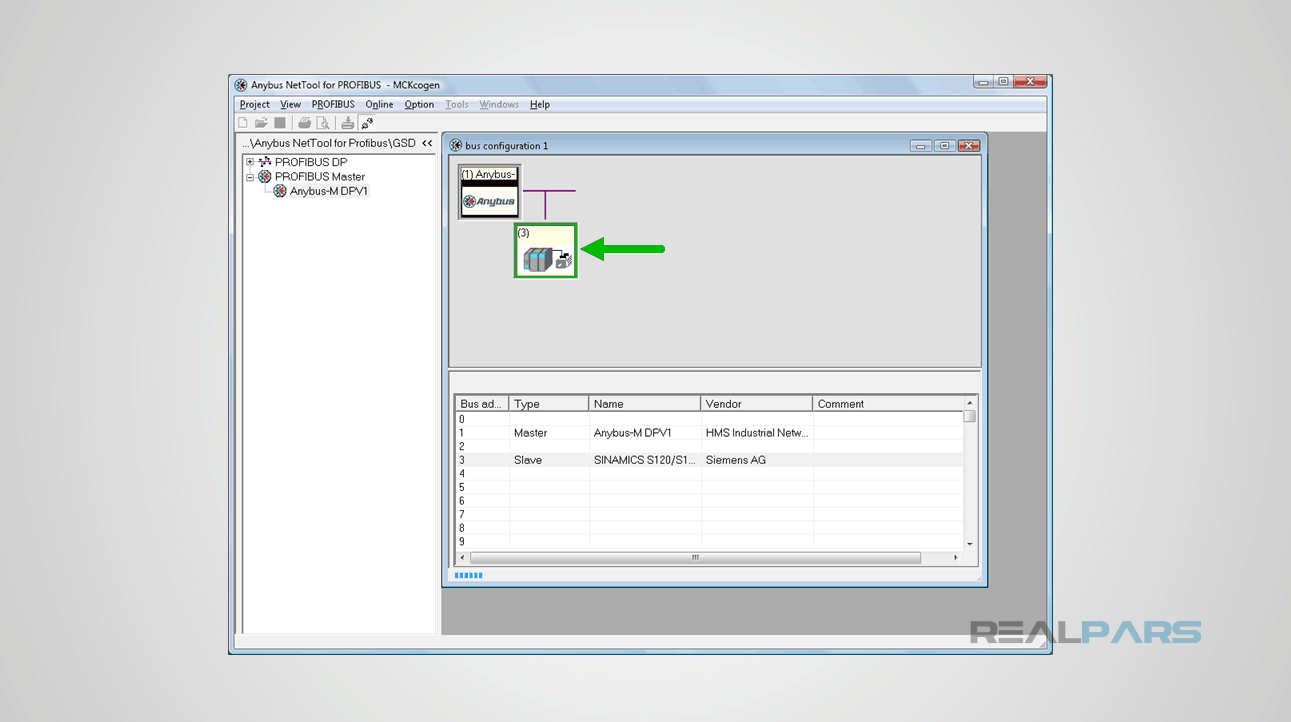
After a successful connection occurs, the Slave icon appears to have a green border, indicating the salve is communicating without error. If there was an error a red border would appear.
To monitor the Robicon tag names and its real-time data values, I can open up the “Online slave properties” window by right-clicking on the highlighted slave name and selecting online properties.
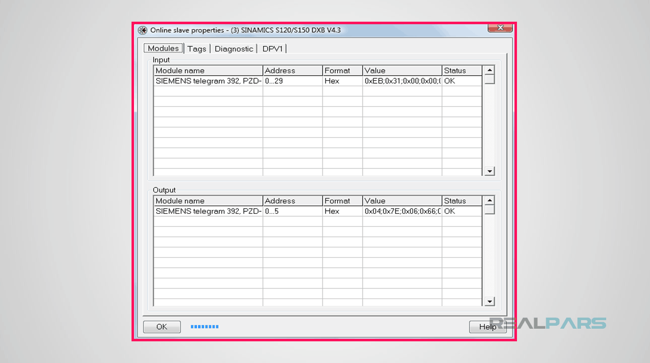
By choosing the Tags tab from the menu I will view the real-time data as displayed in “Online slave properties” window.
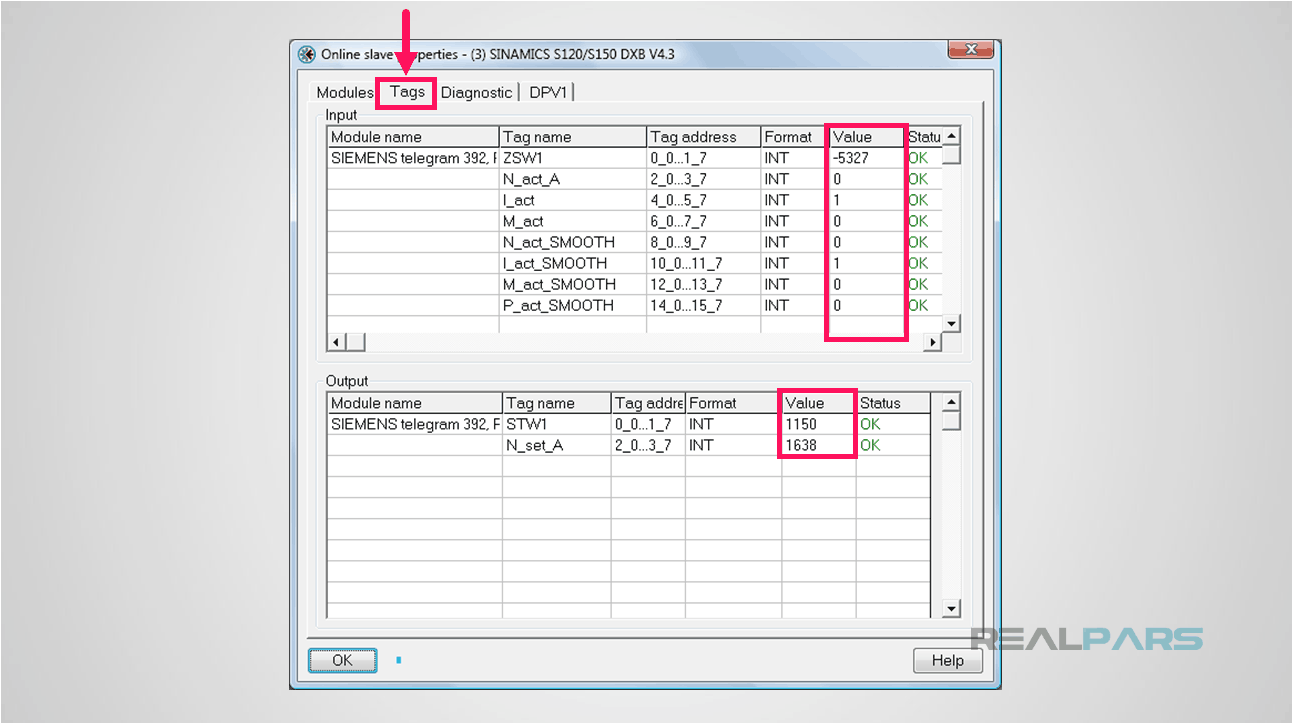
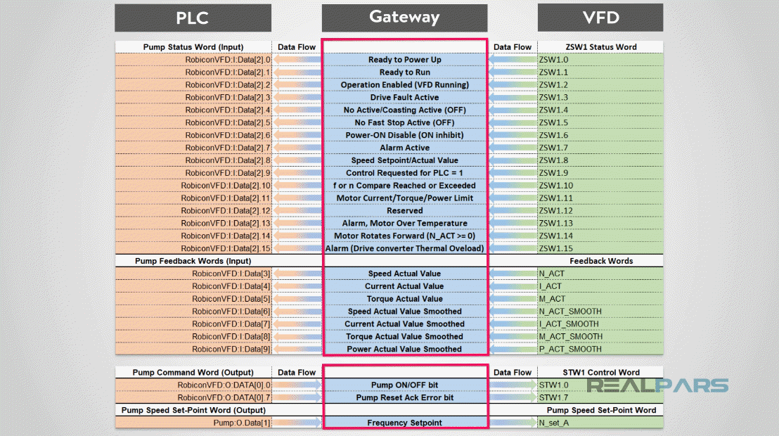
This data correlates to the data we discussed and represented in the chart from Part 1 of this series with the input/output data flow communicated between the HMS gateway.
Next, in Part 3, we will discuss how to configure this input/output data in the Robicon VFD.
This concludes Part 2 of this lesson. Stay connected with RealPars for Part 3 of this series of lessons.
In the lesson , we will discuss how to configure the Siemens Robicon PROFIBUS slave VFD. So stay tuned!
I hope you have enjoyed learning what will support you in your upcoming project. If you would like to get additional training on a similar subject, please let us know in the comment section. Please check back with us soon for more automation control topics.
Got a friend, client, or colleague who could use some of this information? Please share this article.
The RealPars Team
How to Control a VFD with a PLC – Part 1
How to Control a VFD with a PLC – Part 3
How to Control a VFD with a PLC – Part 4
How to Control a VFD with a PLC – Part 5

Learn from
industry experts
with a free 7-day trial, then $25/month