

In modern automation systems, instrument field buses are often used to provide a method of connecting field devices using a trunk-and-drop style bus topology. This type of network structure saves wiring and cabling, allowing for a faster and less expensive installation.
One of the simplest and most cost-effective options for industrial communication is the AS-i bus, or Actuator Sensor Interface.
If you’re new to this technology, don’t worry—this guide will walk you through what AS-i bus is, the different types of network segments, and the steps to construct an AS-i bus segment.
For a more in-depth look at industrial sensors and actuators and exciting new industrial fieldbuses, like Single-Pair Ethernet, go to realpars.com and check out our extensive course catalog. Your door to upskilling is just a few clicks away!
What is AS-i bus?
AS-i bus is an instrument fieldbus that is simple, easy to design, and easy to install. AS-i bus was designed to interface with sensors and actuators on the plant floor using a single 2-wire cable.
Both data and power are transmitted over the same cable. This makes AS-i bus one of the most affordable fieldbus solutions.
AS-i bus is a serial bus, and communication is half-duplex, meaning data can be transmitted only in one direction at a time. The data rate is only 167 kilobits per second, but the simplicity of the network allows a communication turnaround time of only 5 milliseconds.
Each standard AS-i slave device can receive four bits of data and send four bits of data.
Because AS-i bus is so simple compared to Profibus PA or Foundation Fieldbus, even those engineers new to automation fieldbuses can design and set up an AS-i bus network. And as the plant’s footprint grows, AS-i bus networks can grow to accommodate more devices over time.
AS-i bus can be considered to be a plug-and-play system. You don’t need deep technical expertise to get started. Earlier in my career, I was able to learn a lot about instrument fieldbuses by designing and installing AS-i bus systems.
AS-i bus network design
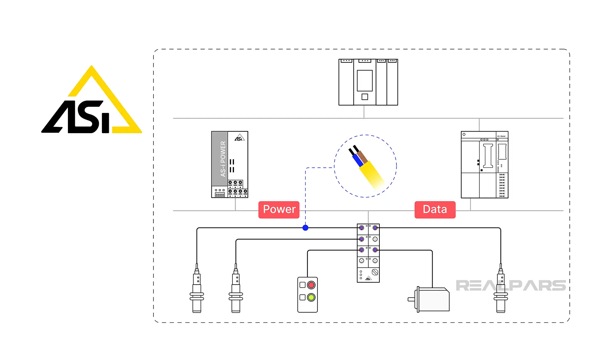
Let’s take a closer look at how AS-i bus networks are designed. AS-i bus networks are divided into segments. Each segment can be thought of as a length of cable from which devices like controllers, sensors, and actuators are connected.
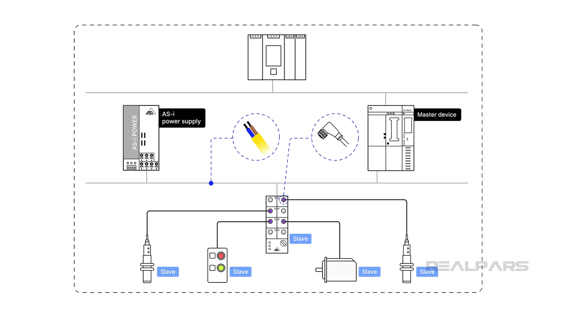
Each segment must contain what is called a master device and a power supply. The master device is used to manage, direct, and control communication over the segment. The master sends commands to the connected devices and receives data from them.
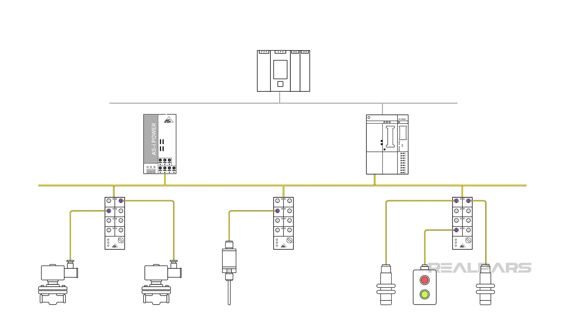
The power supply provides the power for communication as well as to power the individual devices. In the segment here, you can see the various components of a typical AS-i bus segment.
The connected devices are called slaves and consist of devices such as sensors, actuators, and I/O modules. Examples of these devices include valve solenoids, valve position feedback signals, and temperature readings.
So let’s review:
An AS-i bus segment requires a master communication module, a power supply, a length of 2-wire cable, connectors to attach the various devices, and the devices to which we need to communicate.
The master communication module is typically a card that fits into a PLC I/O chassis or a DCS I/O rack. It has terminals for connecting the power supply and the AS-i bus segment cable.
An AS-i bus power supply typically provides power at 30V DC, with varying amperages from 2.6 to 8 amps.
AS-i bus power supplies provide internal circuitry that aids in decoupling the data signal from the power signal. The power supply size is chosen to match the load on the segment.
Typical AS-i bus devices draw on 30-40 milliamps, allowing many devices to reside on a single segment. Slave devices are limited to 170 milliamps to ensure reliability. A standard AS-i segment can support up to 31 slave devices.
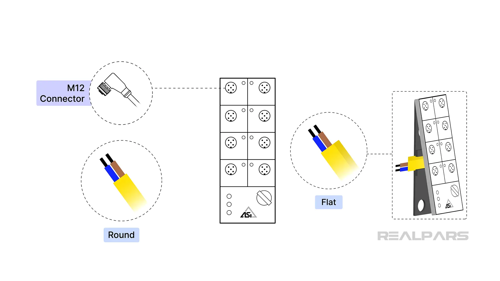
AS-i cables come in a few varieties, including a standard round cable, which is connected by M12 quick disconnects or by terminating the two conductors. AS-i cables are typically yellow in color. Yellow flat cable is often used, and connections are made by simple vampire clamp connections.
AS-i bus, unlike other instrument buses, requires no terminators at the end of the cable. A single AS-i segment may run up to 100 meters. Drops of up to 3 meters from the segment trunk cable are allowed. Longer drop lengths may introduce excess voltage drops and data errors.
Segment lengths of up to 300 meters are possible using segment extenders, a more advanced concept.
Steps to construct an AS-i bus segment
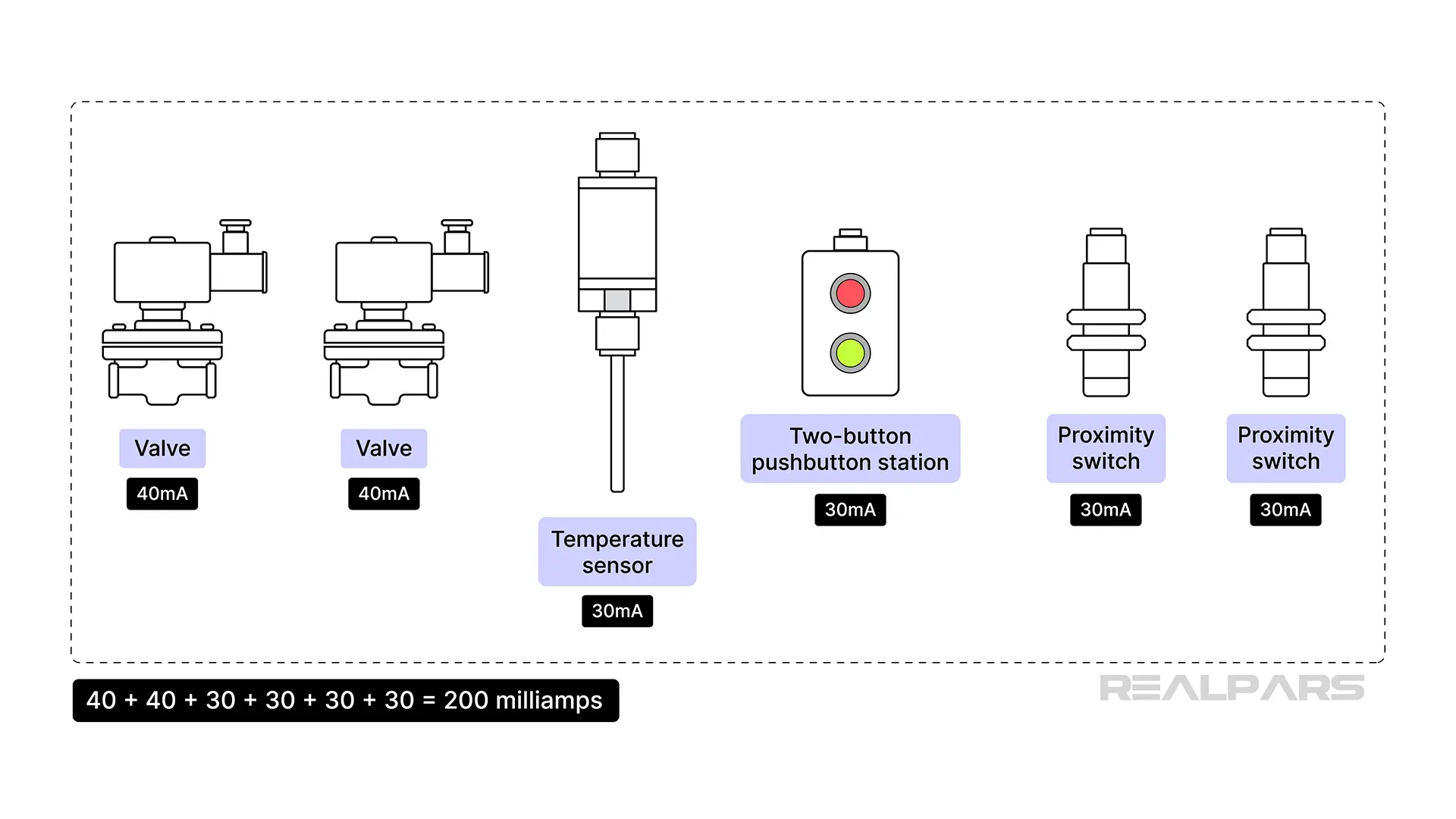
First, we need to plan the network. I will construct a simple AS-i bus segment with six slave devices, including 2 valves, a temperature sensor, a two-button pushbutton station, and two proximity switches.
I have determined from the device manufacturers’ data sheets that I will need 40 milliamps for each valve, and 30 milliamps for the other four devices. This means my power supply will need to provide at least 200 milliamps, a very small amount.
A 2.6-amp power supply will provide more than enough power for my segment. I choose to use standard round cable to install my segment.
Next, I need to see how long my segment will be. I locate where the devices need to go in the process, and since AS-i is a trunk and drop system, I determine 30 meters of trunk cable is sufficient to drop the network to each device. I can use special condulets or passive connection bricks to make connections easier.
I install the power supply on a DIN rail in a nearby remote I/O panel, along with my AS-i master communication card. I install the cabling from the power supply to the master card.
Now I will install the cable. I choose to use basket tray to support the cable and keep it away from sources of electrical interference, such as motor cables. Having support, such as basket tray or conduit, physically protects the cable from damage.
Now, I will install each slave device using an appropriate connector. Each slave needs to have its unique segment address set at the device. Sometimes, this can be done with DIP switches or rotary switches. Often, a special hand-held communicator must be used to set the node address.
With the cabling to the field devices completed, I make the final connection at the master communication card. I power on the segment and ensure there that all of my field devices are receiving power.
I see some error lights on the devices, but that occurs because I have not yet configured all of the nodes in the master. I need to tell the master which nodes should be present. I also need to configure the communication to the PLC or DCS that the master is connected to.
Once I have the configuration complete, the master should be talking to each node. I check for addressing errors, cable faults, and any power supply issues.
Finally, I test the devices by reading statuses and sending commands, depending on the capabilities of each device.
I send open commands to the valves and verify that I receive position feedback. I press each button on the pushbutton stations and trip the proximity sensors to verify proper detection. I check the temperature sensor to see if it is reading the correct temperature for where it is placed.
All good! My AS-i bus segment is installed and working!
Conclusion
AS-i bus is easy to understand and apply to industrial automation designs. AS-i bus is fast, reliable, and very low-maintenance.
In the example I gave, additional devices can be added simply by extending the segment and connecting the additional devices. How much easier could scalability be?
If you want to learn more about Industrial Networking, check out the Industrial Networking Skill Path. There are lots of courses available to help you build your skills.
Expand your team’s automation knowledge by going to realpars.com/business and seeing how we can help your team upskill and prepare for advancement in their careers!