

In this article, I’ll show you how to use Allen Bradley’s Micro800 simulator. By the end of this article, you’ll know how to download a project to the Micro800 simulator, how to simulate inputs for testing, and understand the limits of the Micro800 simulator.
The Allen Bradley Micro800 simulator is a free tool that is used to simulate Allen Bradley Micro800 PLCs. In case you aren’t familiar with them, Micro800 PLCs are a range of small, cost-effective PLCs that are used to control small, standalone machines and skids.
The Micro800 simulator is bundled with Connected Components Workbench since version 12.
Connected Components Workbench is the development environment that is used to configure and program Micro800 PLCs. Unlike many other PLC development environments, Connected Components Workbench is free to download and use.
Since Connected Components Workbench is free to use, includes a PLC simulator, and works with affordable PLC hardware, it is an ideal platform to learn PLC programming with. That’s why we use it in our PLC Programming from Scratch learning series.
This series teaches you PLC programming from first principles using free tools. If you want to learn PLC programming without investing in expensive hardware or software licenses, this could be the learning series for you.
Learn more about PLC Programming from Scratch using this link.
Now that we know what the Micro800 simulator is, let’s see how to use it.
Up and running with the Micro800 simulator
In this example, I have created a project in Connected Components Workbench and added a 2080-LC50-48QWB-SIM controller to the project. This is the part number for a simulated Micro800 controller.
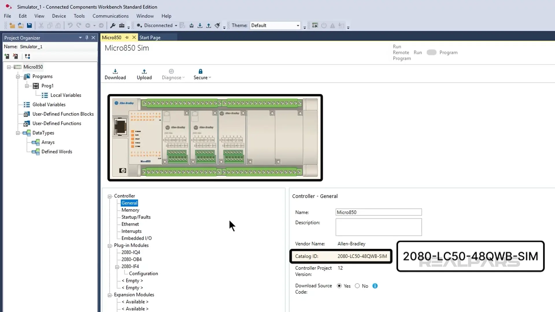
I have also added some plug-in modules to the controller to expand the amount and type of IO available.
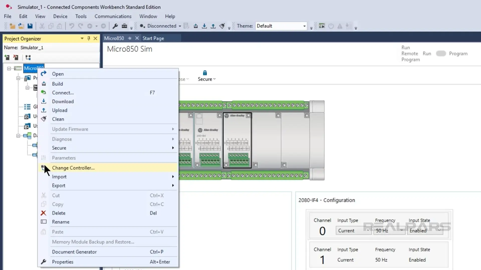
If I want to change the PLC in the project to a physical PLC after I have tested with the Micro800 simulator, I can use the Change Controller feature of Connected Components Workbench to change the controller in the project without losing the configuration data or code.
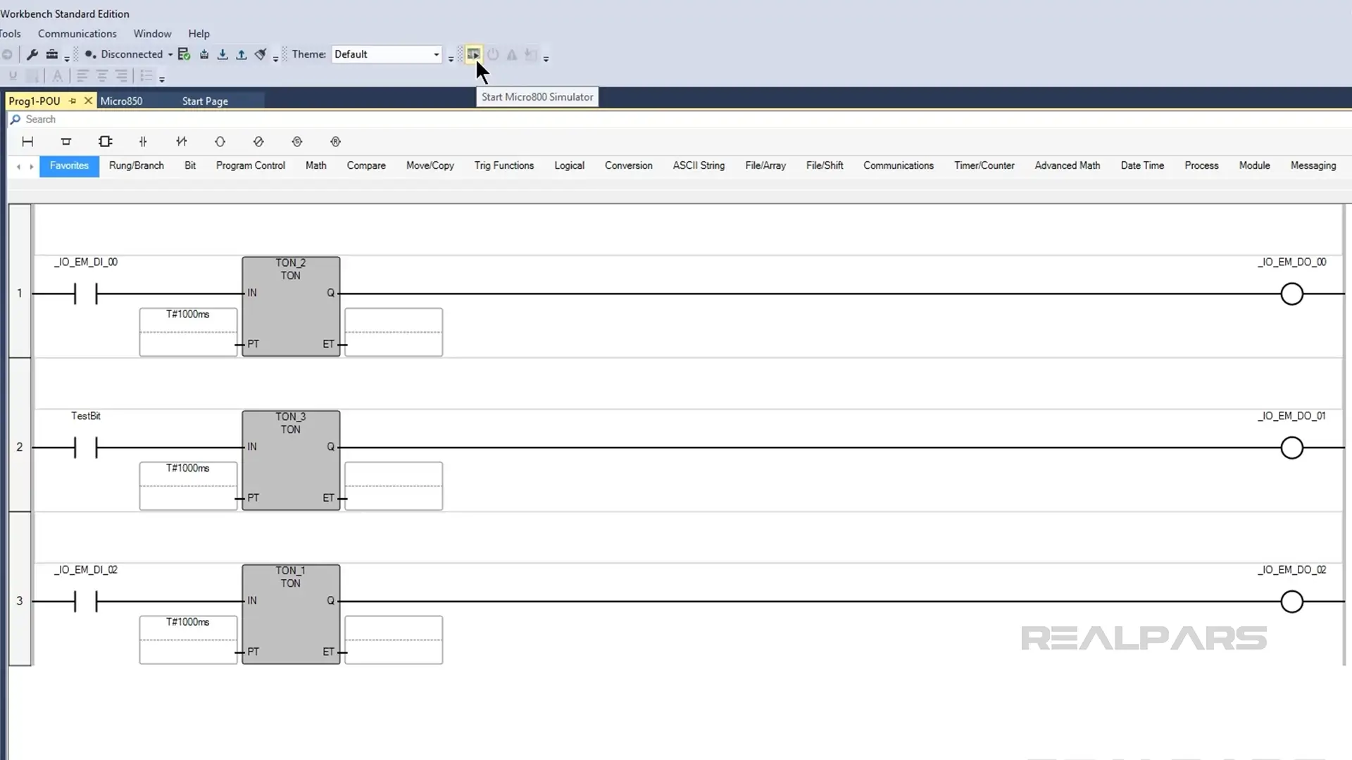
In this project, I have programmed some simple logic to control the outputs in a program called Prog1.
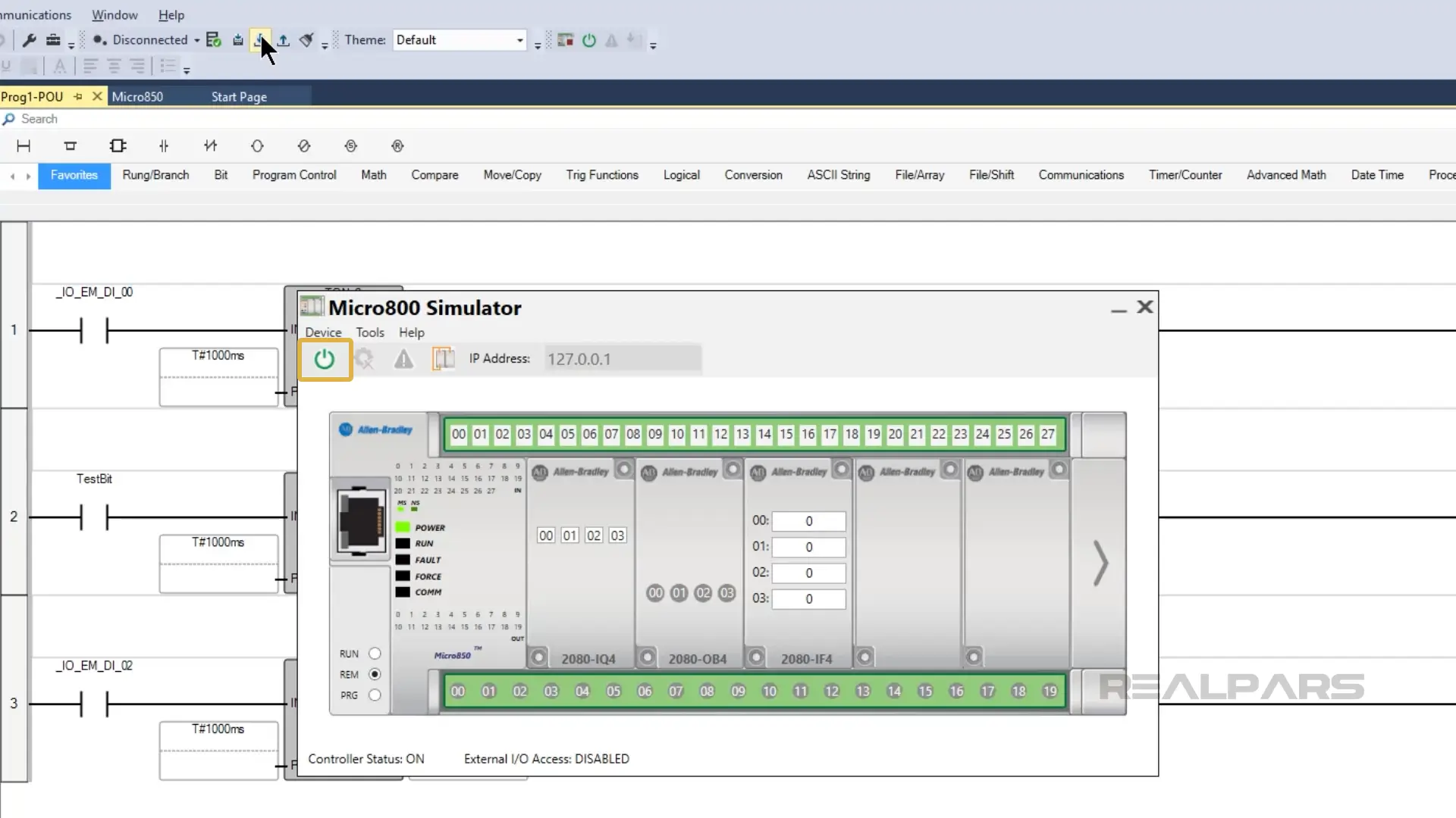
When I’m ready to test the project, I launch the Micro800 simulator using the button on the toolbar.
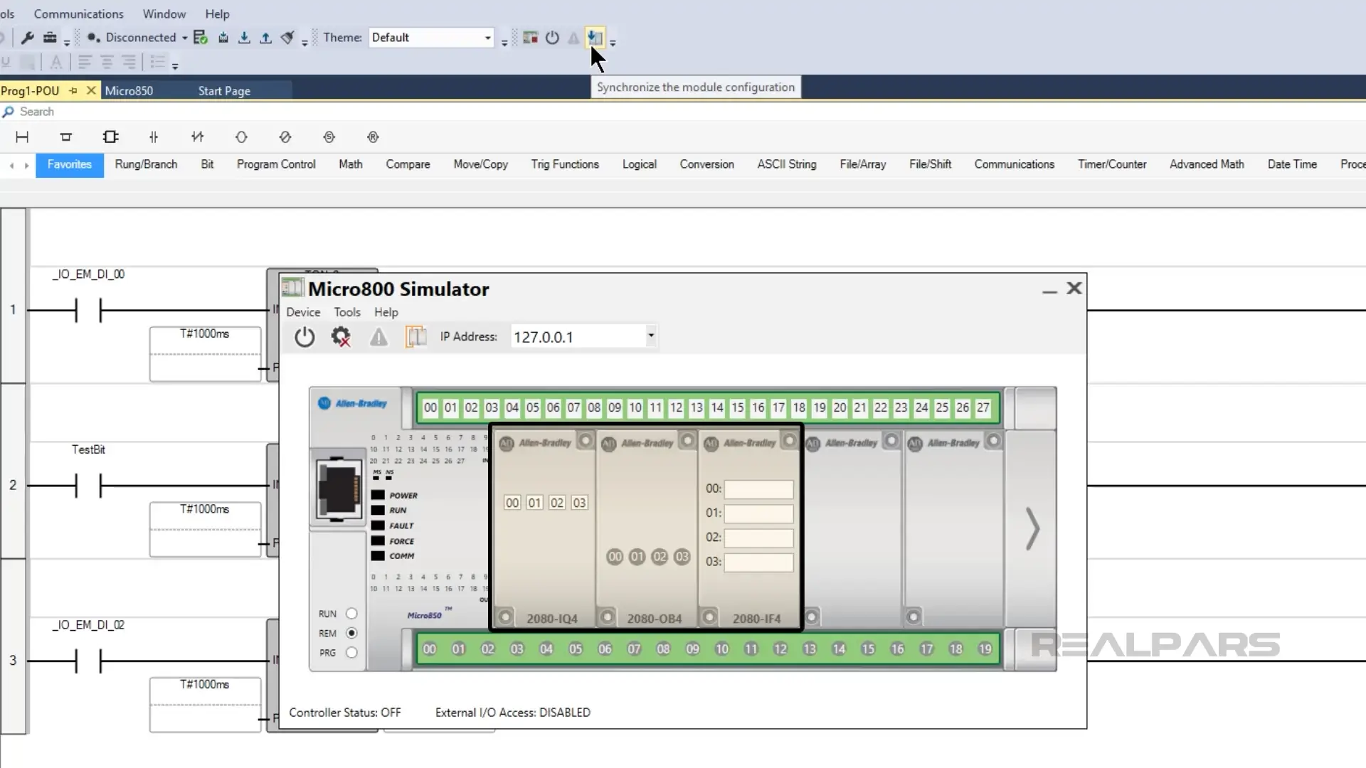
After launching the Micro800 simulator, I can synchronize the configuration of the simulated PLC with the project by clicking on the Synchronize button.
After synchronizing, the plug-in modules have been added to the simulated PLC.
Before downloading the project to the simulated PLC, I need to power it on. I do that by clicking on the power button.
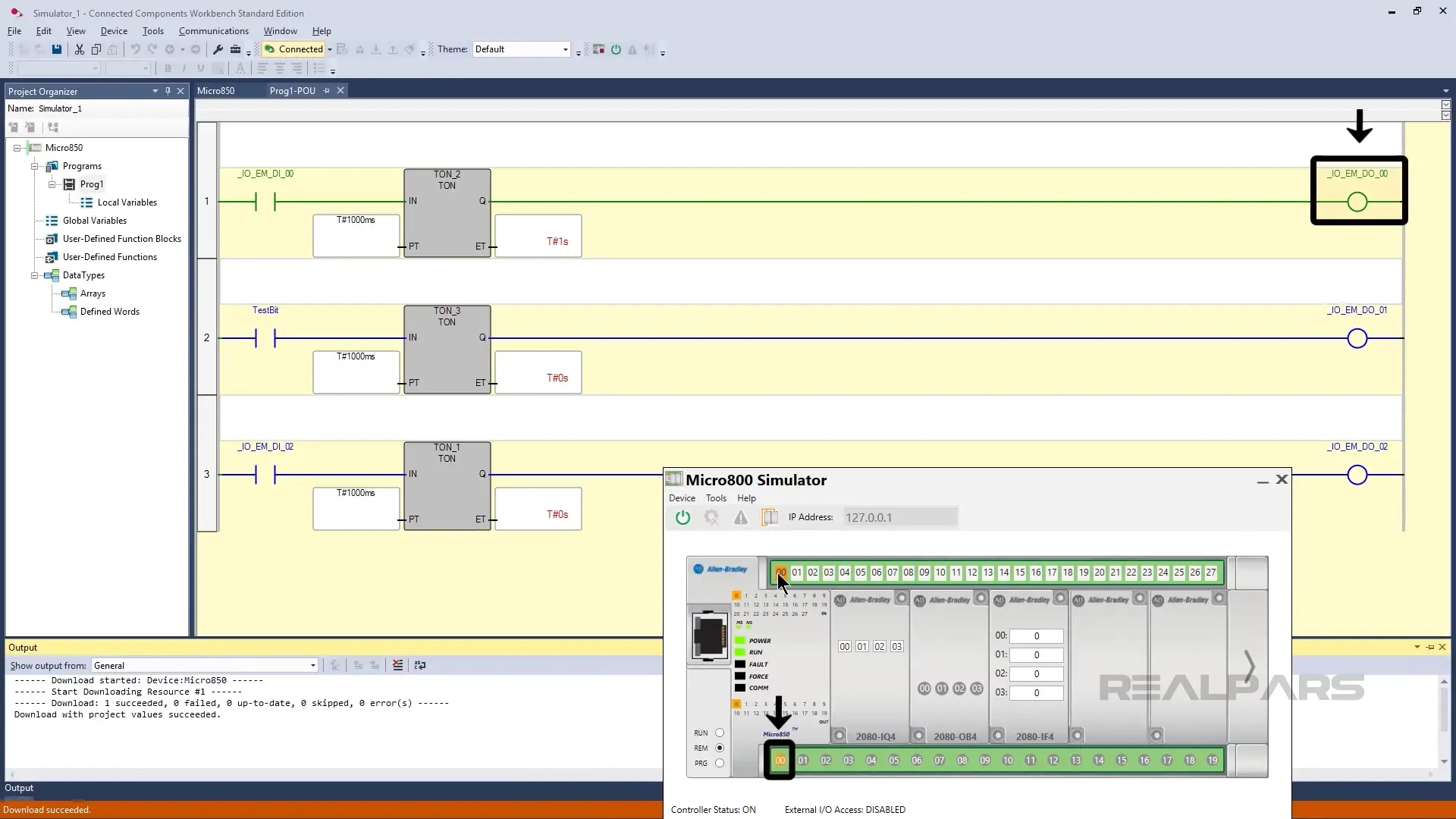
Once the simulated PLC is powered on, I can download the project to it like a normal PLC.
Once the download is complete, I click Yes to put the simulated PLC into Remote Run mode.
After downloading the project, Connected Components Workbench automatically connects to the PLC so that we can monitor the project’s logic online.
To test this logic, we’ll need to simulate some inputs to the system.
Simulate inputs
The Micro800 simulator provides a few different ways to simulate inputs.
Simulating inputs via interface
The easiest way to simulate inputs is to control them in the Micro800 simulator interface. You can click on a digital input to toggle its value or enter a value for an analog input.
Here I am toggling input0 to True. After a one-second delay, output0 becomes True.
Virtual I/O wiring setup
I can also virtually wire outputs to inputs. This lets you programmatically control inputs for testing.
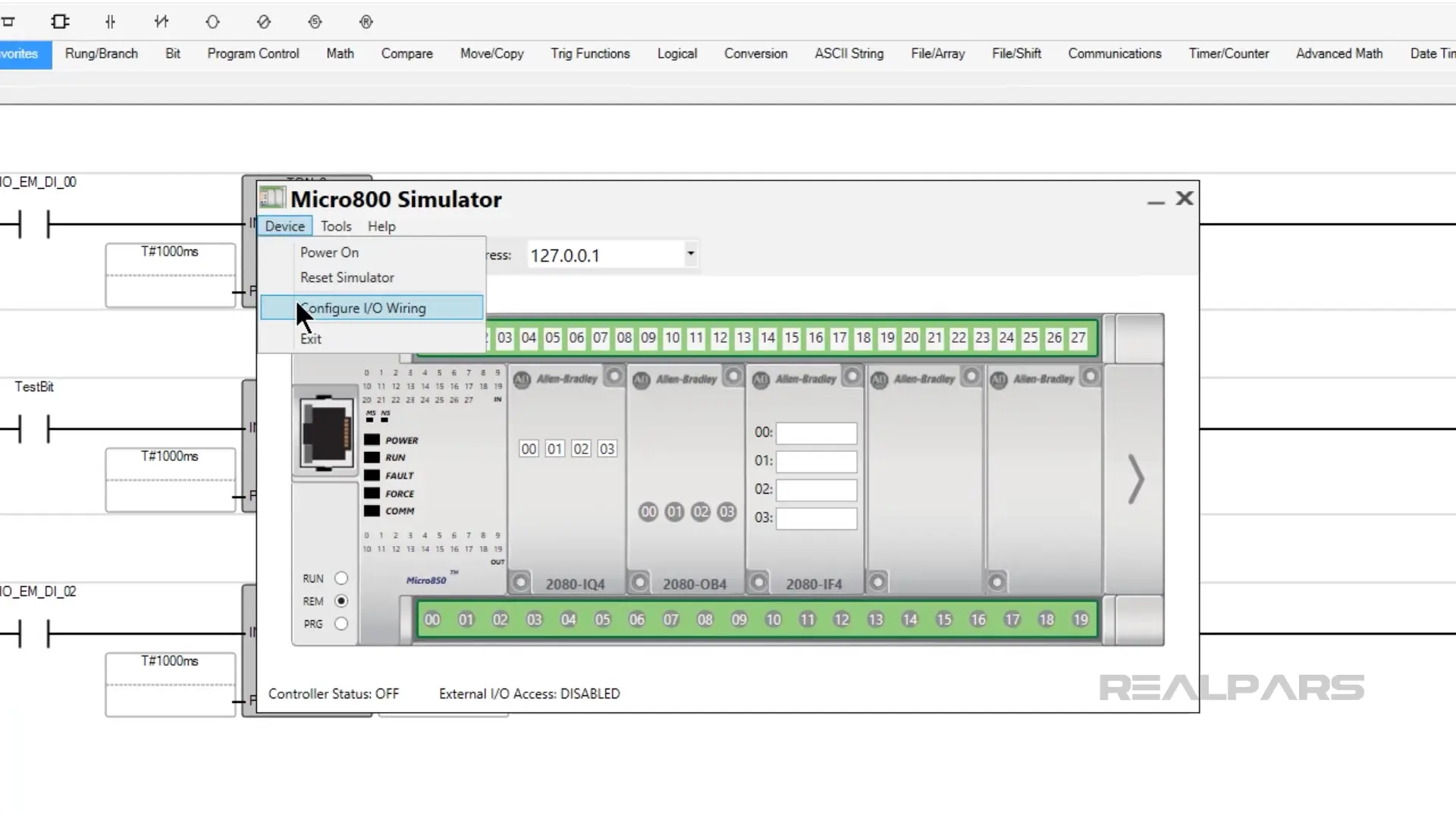
To configure the virtual IO wiring, I close and reopen the Micro800 simulator and select Configure I/O Wiring from the Device menu.
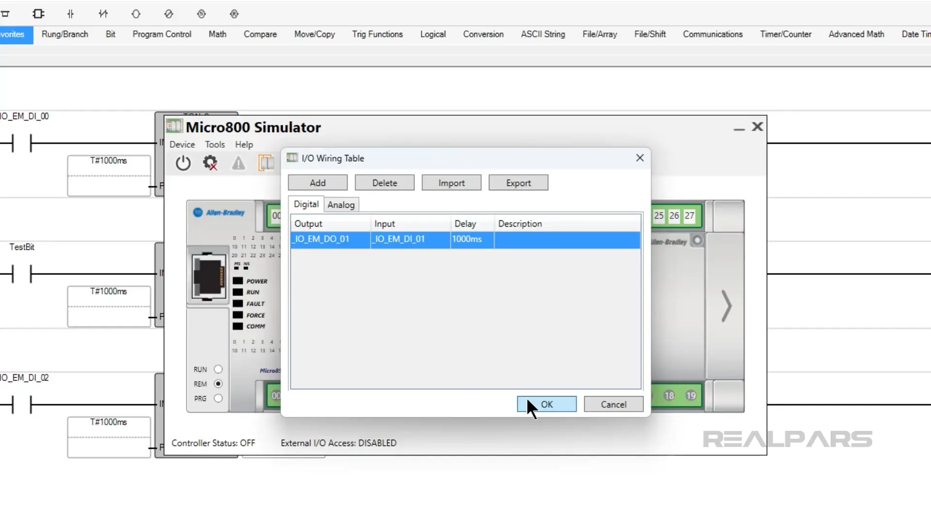
In the IO wiring table, I use the Add button to create a connection between output 1 and input 1. I also create a delay of one second between the output turning on and the input turning on.
Then I click OK to save the virtual wiring.
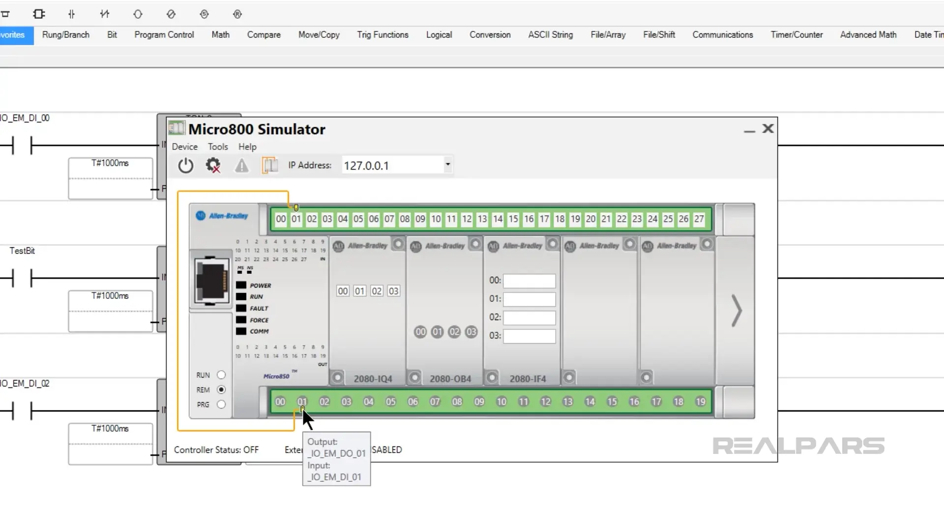
Now, when I hover over output 1 or input 1, I can see the virtual wiring.
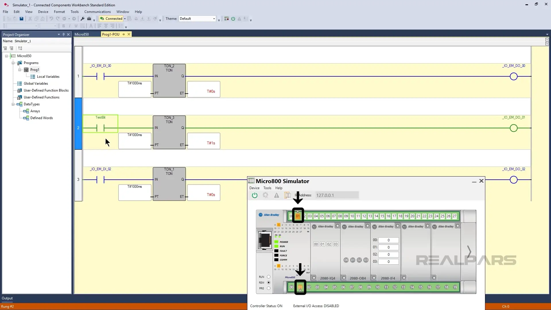
With my virtual wiring complete, I power up the PLC again and connect to it in Connected Components Workbench.
Then I toggle the TestBit in my program to turn on output 1, and after a 1-second delay, I see input 1 become True.
Using external applications
Finally, you can simulate inputs using external applications. There are two interfaces available to simulate inputs through external applications. They are an XML file and an API.
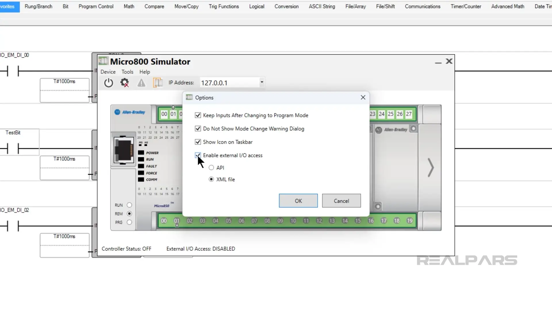
To simulate inputs using an XML file, you can enable external IO access using the XML file in the Options dialog, which is accessed by clicking on Tools > Options.
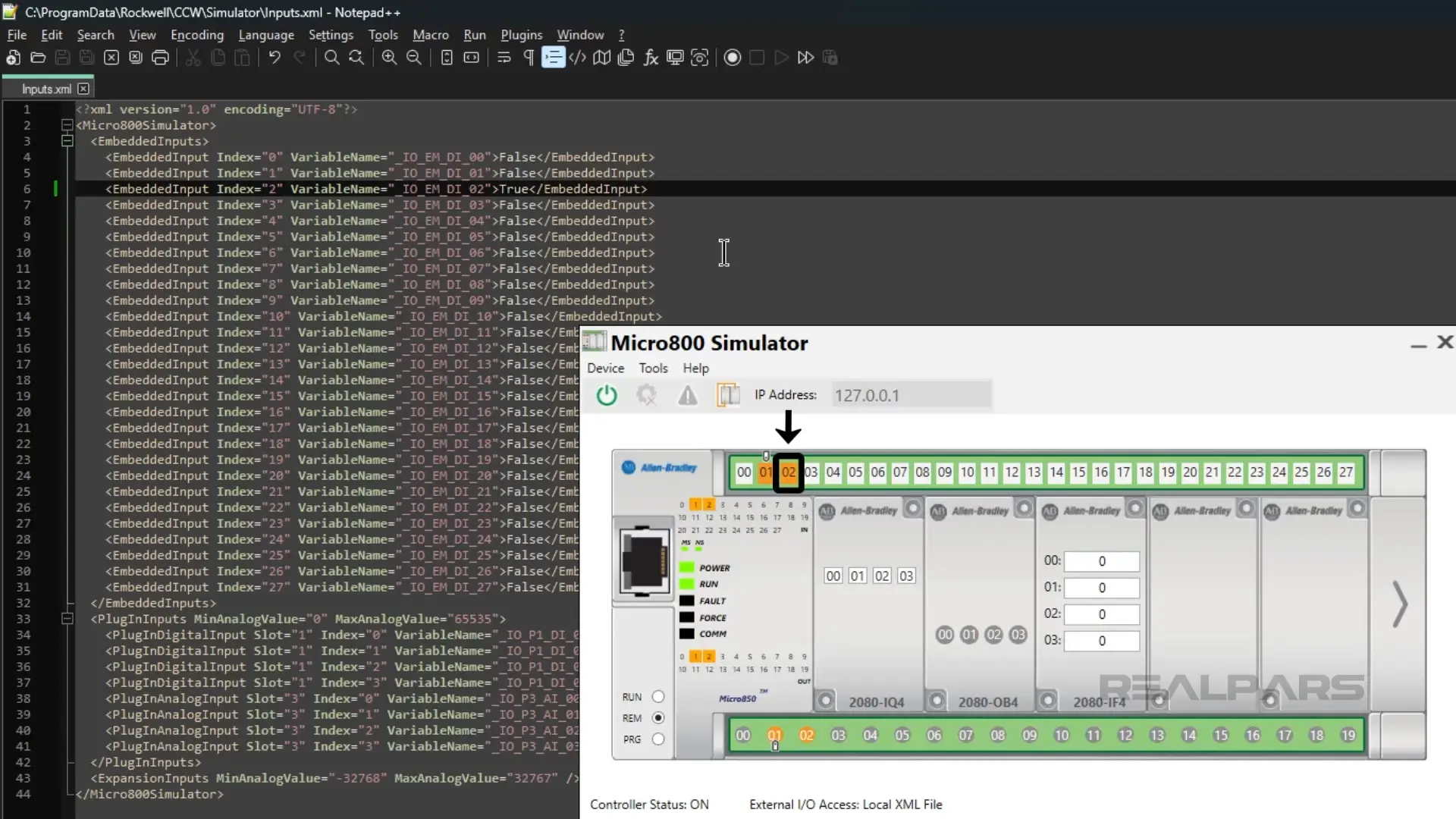
Once external IO access is enabled, you can modify the inputs.xml file, which is located in the folder C:\ProgramData\Rockwell\CCW\Simulator.
In this file, I change the value of input 2 to True, and I see that it changes on the Micro800 interface as well.
You can also use an API, or application programming interface, to simulate the inputs. This method is more complex than the others and is outside the scope of this article.
Limitations
The Micro800 simulator is a powerful tool for testing, but it is not designed to be a replacement for a physical PLC. It has some limitations that a physical PLC does not have.
The most important limitation of the Micro800 simulator is related to performance. The performance of the Micro800 simulator will depend on how powerful your computer is and how often the simulator is interrupted by other applications.
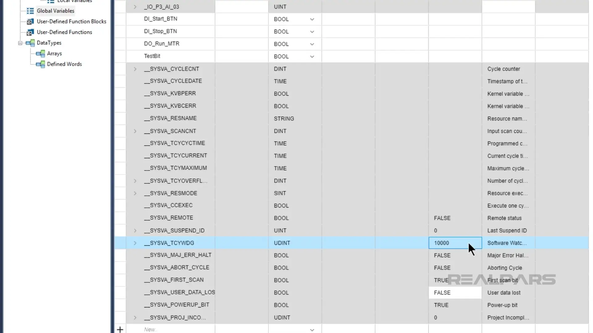
On most computers, the scan times of the simulated PLC will be quite long, and you may encounter watchdog faults while testing. To avoid watchdog faults, you can set the watchdog time variable _SYSVA_TCYWDG to a high value, like ten thousand.
The second most important limitation is the runtime limit. The standard version of the Micro800 simulator only stays in run mode for 10 minutes. After this time, it automatically switches to program mode.
If you need to run the Micro800 simulator for a longer time, you can invest in the Developer Edition of Connected Components Workbench. This is an enhanced version of Connected Components Workbench that includes a version of the Micro800 simulator that stays in run mode indefinitely.
Wrap-Up
In this article, I introduced the Micro800 simulator and showed you how to get up and running with it.
By now, you should know how to launch the simulator, download a project to the simulator, and use a variety of techniques to simulate inputs for testing. You should also understand the limits of the Micro800 simulator.
If you want to keep learning how to use Connected Components Workbench to program Micro800 PLCs, you can check out our PLC Programming from Scratch courses. These courses teach you PLC programming from first principles using free tools and, optionally, affordable hardware.
I hope to see you on a PLC Programming from Scratch course in the future.
One final note: If you're a plant manager looking to train your team with RealPars courses, don’t forget to check out realpars.com/business.