In this article, we will discuss PID controllers, what they are and what they do, their evolution to modern-day industrial applications, and finally, a few newer control approaches.
What is a PID controller?
A PID Controller's purpose is to maintain a process variable at a desired setpoint automatically.
How is this accomplished?
In a control loop, a process variable is constantly being measured and compared against a desired setpoint, which a human operator usually establishes.
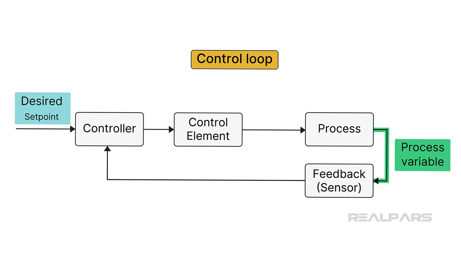
Suppose a difference exists between the measured value and the desired setpoint value. In that case, corrective action will occur on a manipulated variable to bring the process variable closer to the set point.
Sounds easy enough, huh!
Car temperature example
We’ll apply this concept to the interior temperature control of a car.
Let’s say you are rolling along the highway when the outside temperature changes, causing the interior temperature to drop.
The new cabin temperature is sensed, fed back to the controller, and compared with the desired setpoint temperature. The controller will move dampers or valves, mixing outside air with engine-heated air, to increase the cabin temperature until it reaches the setpoint.
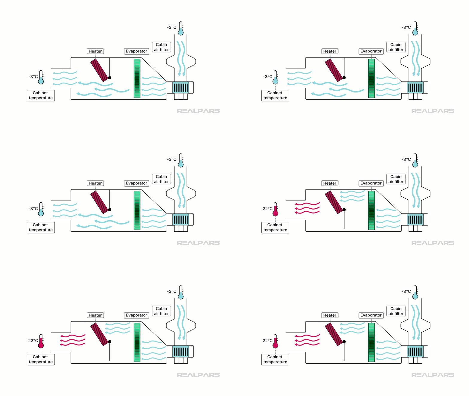
Are the dampers opened fully? Are they throttled? How quickly do they move?
That's where the "P," "I," and "D" of PID control become essential.
We don’t want the cabin temperature to increase past the setpoint or too slowly. Obviously, damper movement is critical.
The PID algorithm determines the control action.
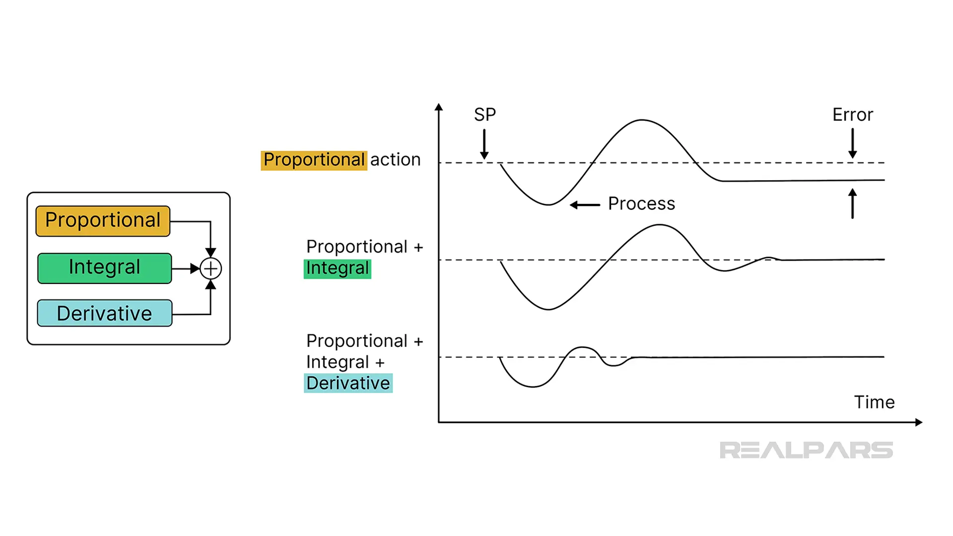
“P” stands for Proportional, “I” stands for Integral, and “D” stands for Derivative.
Adjusting these parameters changes how the controller responds.
Proportional looks at the current value and provides an adjustment based on its difference from the setpoint. This difference is referred to as the error.
Integral looks at the changing error, and Derivative tries to predict where it is going.
The P and I terms tell the corrective action to Keep going.
Derivative catches the corrective action and says, You’re going too fast. You need to slow down.
In this article, we're not attempting to teach you about PID theory.
If you are interested, check out our PID Controller Basics course.
Evolution of PID controllers
Many automation and control folks credit Elmer Sperry for inventing the simple feedback PID controller in 1911. Elmer created a system to control a ship's rudders to help prevent it from sinking due to waves and other external forces.
The first practical industrial PID controllers emerged in the 1940s, such as the Foxboro 43P pneumatic controller.
The introduction of electronic PID controllers, such as the FOXBORO SPEC 230SM CONTROL STATION, led to the widespread use of PID control in process industries.
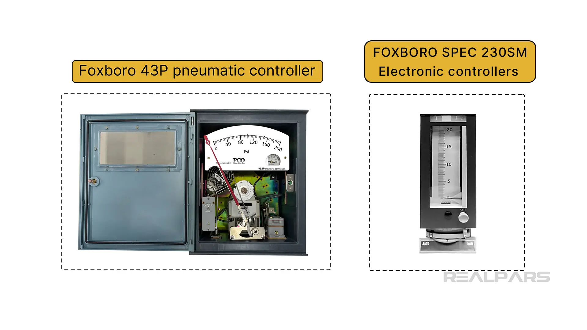
Control Rooms were filled with single-station controllers mounted on panels, each managing one process variable or control loop.
A Piping & Instrumentation Drawing (P&ID) shows how equipment, valves, and instruments are connected in a process.
A discrete standalone Level Indicating Controller (LIC) located on a control panel and accessible by an operator is displayed using a circle with the device tag number printed inside.
PLCs and DCS control systems
Single-station controllers have all but disappeared from industry.
Today, we have PLCs and DCS platforms that are capable of managing multiple processes via centralized control, resulting in faster data processing and analysis.
For example, the AB Controllogix PLC 1756-IF8 analog input module can receive process measurement data from up to 8 separate processes. PID control is managed via the RSLogix 5000 programming language, or the newer version Studio 5000 Logix Designer.
A DCS is a computerized control system with multiple autonomous controllers that operate and control many control loops.
Field devices are connected to Controllers with multiple I/O modules located in cabinets. The controllers are networked using many communication protocols, such as Ethernet or Modbus. Operator station HMIs are located in a centralized control room.
The Operator station allows plant operators to observe and adjust real-time plant conditions. An engineering station HMI is located in an area only accessible for actual control logic programming changes for any of the many control loops.
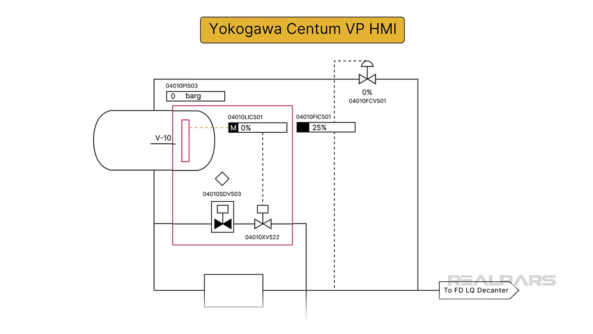
Here's an example of a Yokogawa Centum VP HMI display. The Level Indicator Controller (LIC501) is set to Manual mode and currently shows a reading of 0%. The controller's output operates a valve XV522.
How is a DCS controller shown on a P&ID?
We draw a square box around the discrete standalone symbol to indicate a DCS controller.
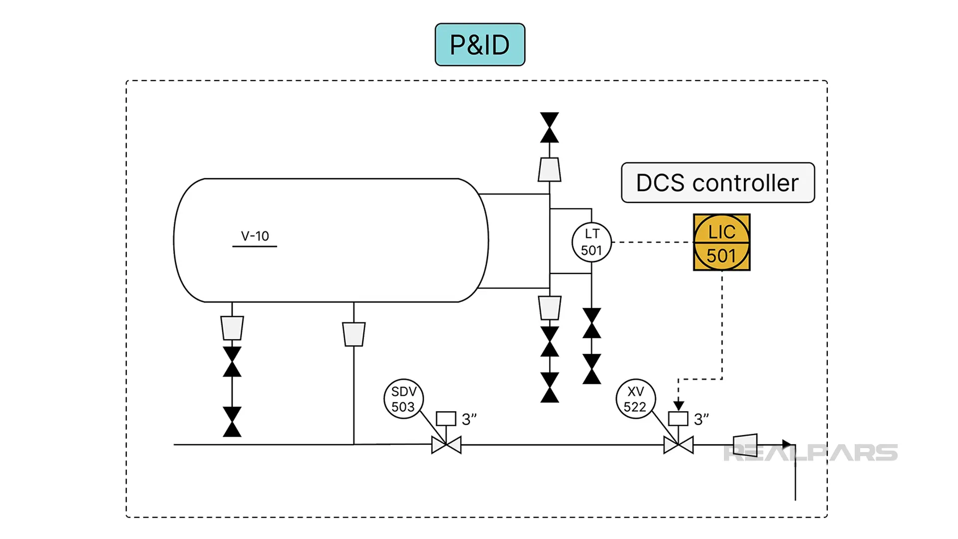
A simplified P&ID from our Yokogawa example shows the level controller and the valve XV522.
Of course, not all DCS HMIs have the same appearance.
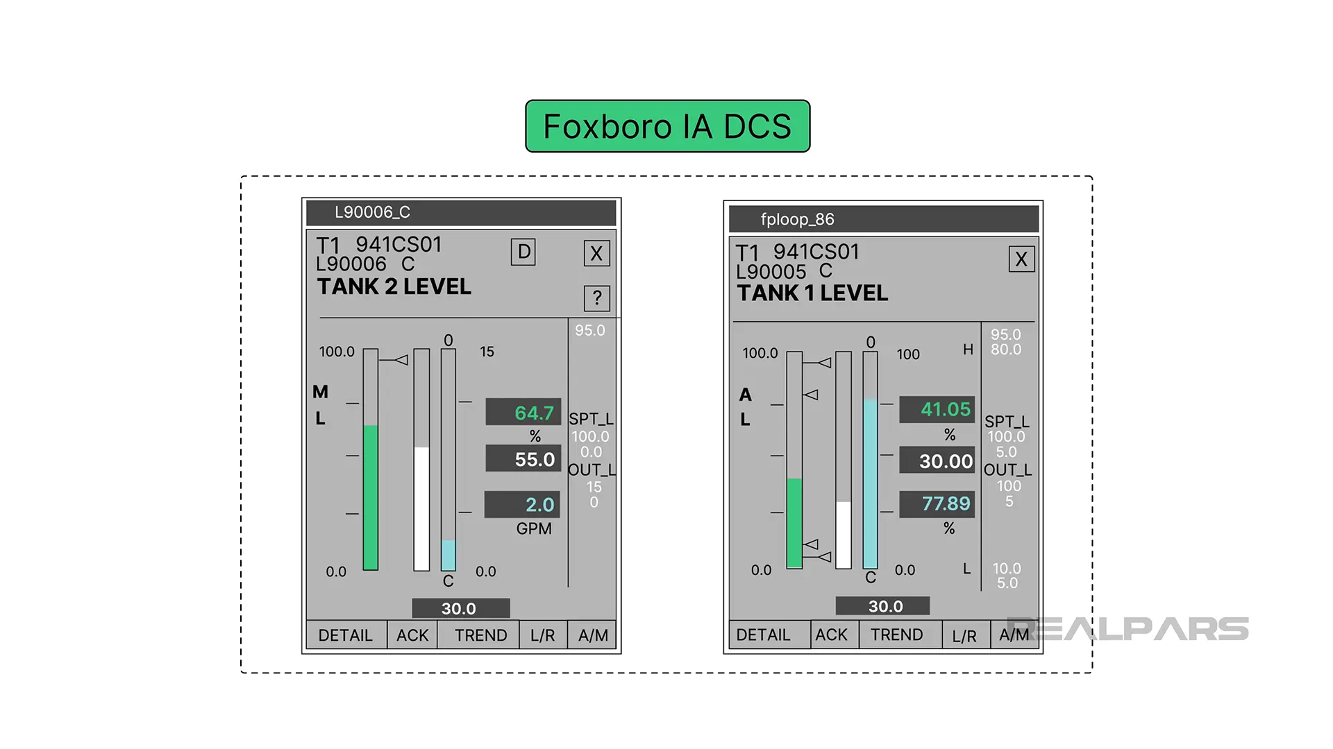
Controllers on a Foxboro IA DCS HMI are designed to resemble the face of a traditional single-station controller.
Applications and tuning of PID controllers
PID Controllers are used in almost all industries to control various process variables.
To name a few:
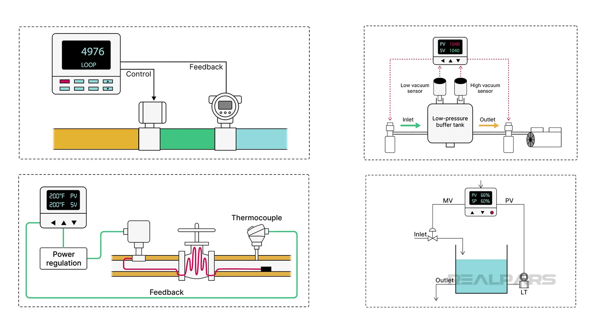
Temperature controllers are used in manufacturing to ensure precise temperature management, such as in food production and chemical processing.
Flow controllers manage the flow of oil, gas, and steam in pipelines, refining operations, and other production processes in the oil and gas industry.
Pressure controllers are used in Petrochemical Processing to manage pressures in distillation columns and separators.
Level controllers are often found in chemical processing plants. They are typically used to maintain liquid levels in tanks and vessels within a specific range.
Acceptable responses to setpoint changes or disturbances differ depending on the application. For example, a quarter-wave damped response may be acceptable in a level control loop but disastrous in a motion control system.
In a Motion Control system, the actual position must closely follow the target or setpoint position.
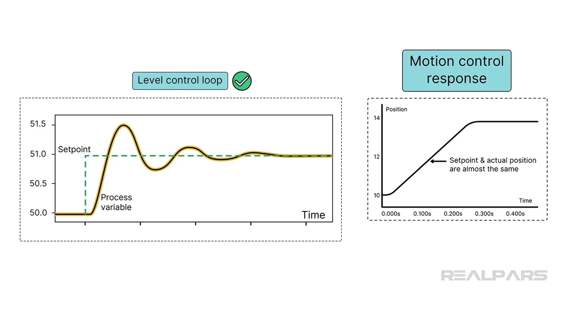
Attaining the desired response is where the flexibility of PID control truly stands out.
Control loop tuning is adjusting the P, I, and D parameters to achieve optimal performance.
There are lots of controller tuning methods.
Engineering students are familiar with traditional tuning methods such as Ziegler-Nichols, Cohen-Coon, and Reaction Rate methods.
The disadvantage of traditional tuning methods is the system upset requirement to obtain valuable process response data. For example, the Ziegler-Nichols Method requires the process to be placed in a state of constant oscillation, which can be impractical or dangerous.
DCS controllers often have built-in algorithms that automatically adjust PID parameters without nasty system disruptions.
Whatever tuning method is used, final tweaks by seasoned professionals are often required to fine-tune the system.
Other control methods
Hopefully, we haven't given you the impression that PID controllers are the only choice for process control in the industry.
Other control methods include Fuzzy Logic Control (FLC) and Model Predictive Control (MPC).
PID controllers are the most common because of their familiarity and functionality.
FLC is suitable where human input or linguistic variables are involved, such as consumer appliances.
MPC works well in systems with multiple interacting variables, such as industrial processes, robotics, and autonomous vehicles.
Alright, that wraps up this article! We hope you enjoyed it and found it helpful.
If you want to learn more about PID controllers, make sure to check out the current courses we have available on this topic in the RealPars course library. The first course is PID Controller Basics and the second course is How to Configure a PID Controller.

