Programmable logic controllers receive and transmit analog signals intended to perform various tasks. PLC inputs routinely handle analog signals representing variables such as temperature, pressure, and flow.
PLC outputs produce analog signals controlling final actuators such as valves and dampers. In this article, we will discuss the different types of analog input and output field devices and associated signal conditioning often used.
Digital vs. analog signals
To begin with, let’s discuss the difference between a digital signal and an analog signal.
What is a digital signal?
The digital part is easy. A digital signal has only two possible conditions: ON or OFF, YES or NO, UP or DOWN, ONE or ZERO.
Let’s look at a pressure switch, a digital field device that operates at a specific pressure of 15 psi. This means the switch is OPEN at pressures below 15 psi and CLOSED at pressures above 15 psi.
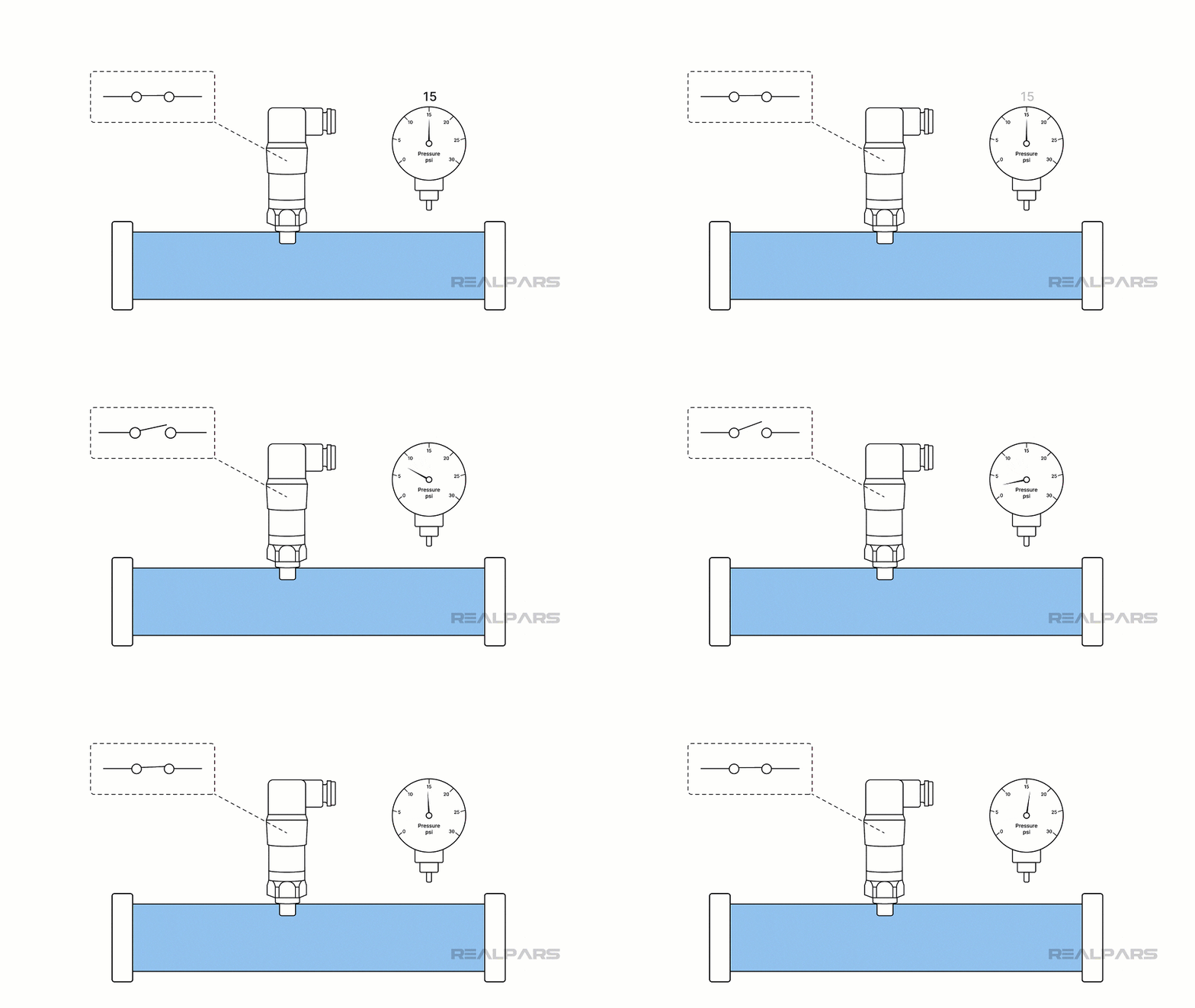
We can connect this switch to a digital PLC input with a bit of simple wiring.
What is an analog signal?
Ok….so…here’s a question….. What if we want to know the exact pressure? Is there a device that will tell us when the pressure is 22 psi or 12 psi? We need a pressure transmitter that produces an analog signal representing the measured pressure.
How many possible conditions are there in an analog signal? Well, a lot more than two. In fact, there are an infinite number of possible conditions.
Transmitters produce voltage or current analog signals representing process variables such as pressure and temperature.
PLC analog input signals
OK…let's look at PLC voltage and current analog input signals and where they originate.
Typical voltage signals include 1 to 5 volts, 0 to 10 volts, and -10 to +10 volts.
The most commonly used analog signal is a 4 to 20 mA current.
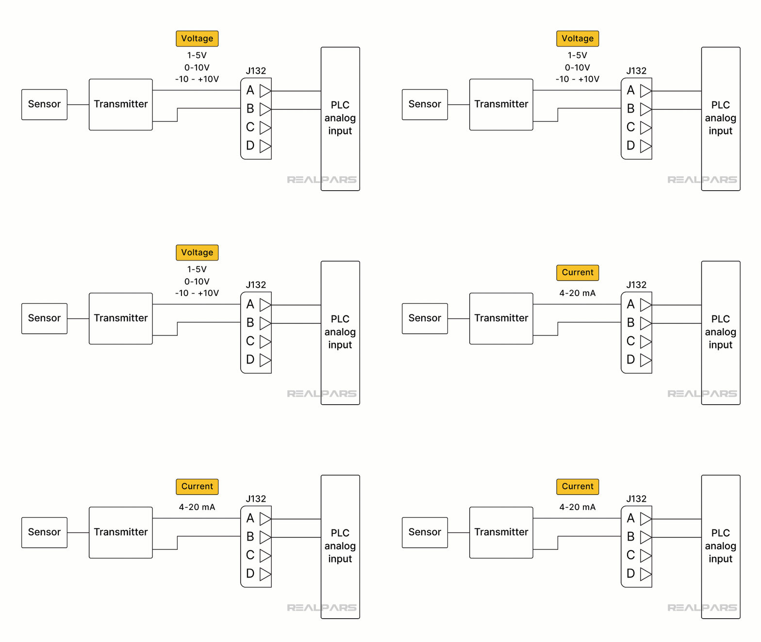
If you're interested in how a transmitter can be physically wired and you're a RealPars member, you can check out this course on Transmitter Basics.
Alright…let’s go back to our pressure transmitter problem. How do we know when the pressure is 22 psi or 12 psi?
Most transmitters are signal conditioners calibrated to produce a current range of 4 to 20mA, representing a specific pressure range.
OK…so we've got a 4 to 20 mA signal representing a specific pressure range that we will send to a PLC analog input module.
PLC analog input modules
We can also use the same analog input module for flow and level measurement! Why? Because the 4 to 20mA signal can represent any variable.
For example, the Allen Bradley ControlLogix 1756-IF8 analog input module can connect up to 8 channels or input loops.
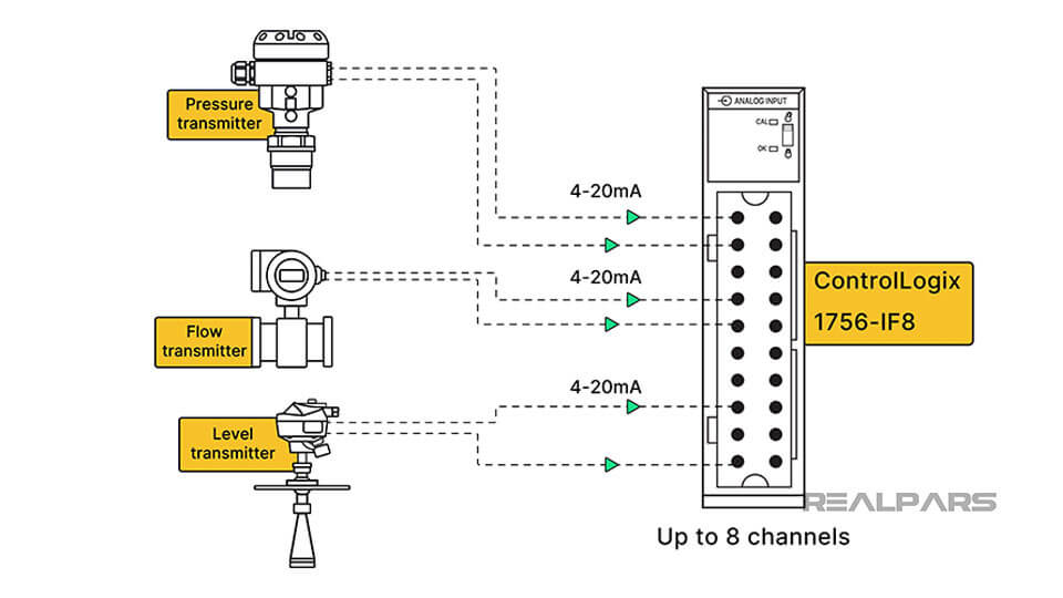
Again, if you're a RealPars member, you can learn more about how a temperature transmitter can be calibrated in the Transmitter Basics course.
Direct sensor connections
Are there analog input modules that connect directly to a sensor, thus eliminating the need for a transmitter? The answer is Yes.
Resistance Temperature Detectors (RTDs) or Thermocouples are used for most industrial temperature sensing. As illustrated earlier, temperature sensors can be connected to a transmitter, producing an analog signal of 4 to 20 mA, representing a temperature range.
RTDs and thermocouples
RTDs and thermocouples can be directly connected to a PLC analog input module such as the Allen Bradley Controllogix IRT8I eliminating the need for a transmitter. This type of connection has pros and cons.
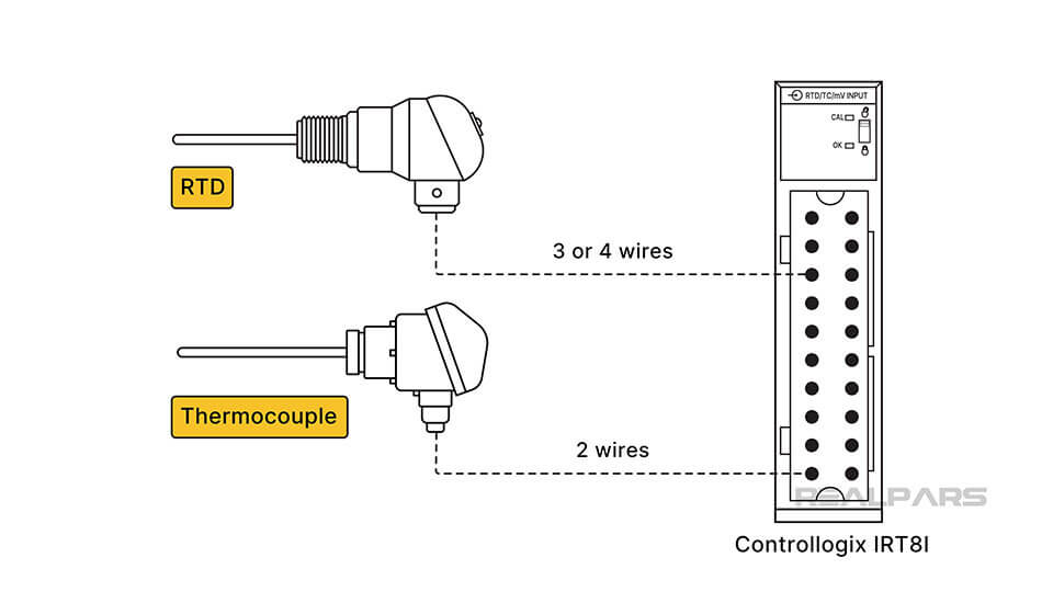
The RTD changes resistance with a temperature change, and a thermocouple produces a change in voltage with a temperature change. Issues with wire length between the RTD and the module and differing temperatures between the thermocouple sensing location and the module need attention.
Load cells and analog input module
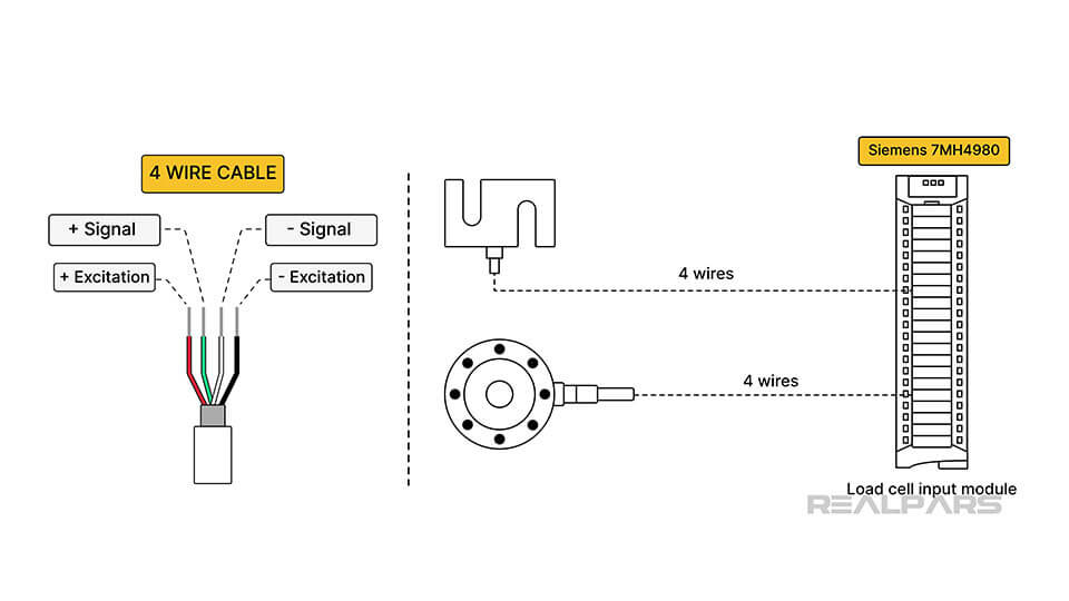
Let’s discuss the Siemens 7MH4980, an analog input module connecting directly to a load cell. This type of module is often called a load cell input module.
Load cells come in different shapes and sizes depending upon their application. But, they all have at least four wires. Two wires are for excitation, and two are for the resulting signal.
PLC analog output modules
Let’s move on to analog PLC output modules.
Analog PLC Outputs control devices such as actuators, motors, and control valves. Usually, the module itself does not provide the drive for the controlling device, only the control signal.
For example, a pneumatic valve is operated by a Current-to-Pressure Converter, or I/P converter, that receives an analog control signal from a PLC output module.
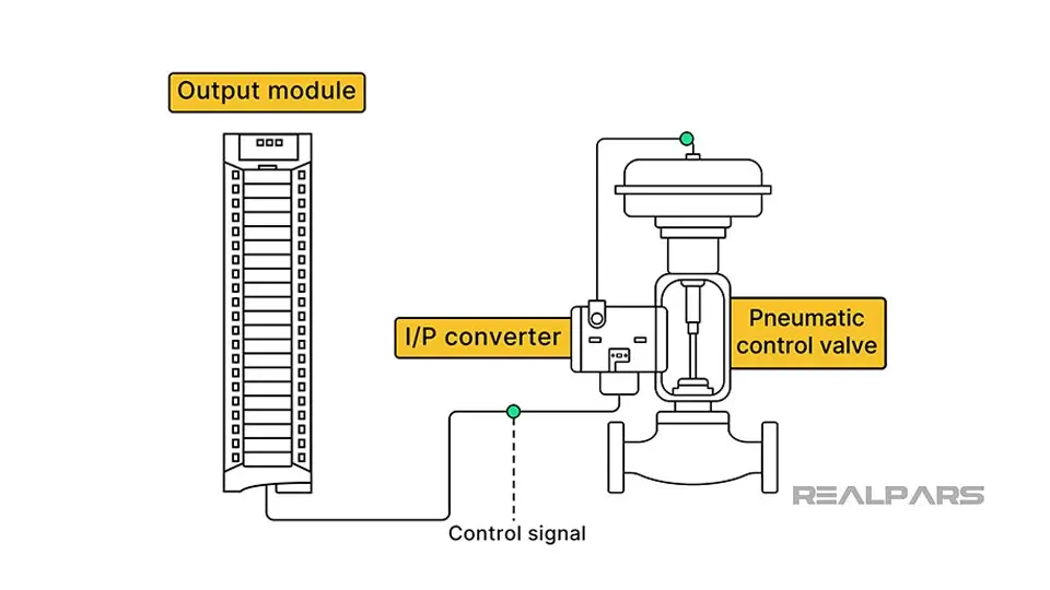
Just like on the input side of the PLC, typical output voltage signals include 1 to 5 volts, 0 to 10 volts, and -10 to +10 volts. The most commonly used analog output signal is a 4 to 20 mA current.
An example of a typical analog output module is the Allen-Bradley Controllogix 1756-OF8, which can control eight separate voltage or current devices.
Wrap-Up
That should do it for this article.
Ok…let's review…
- A digital signal has only two possible conditions, while an analog signal has infinite possible conditions.
- Transmitters produce voltage or current analog signals representing process variables such as pressure and temperature.
- Typical analog voltage signals include 1 to 5 volts, 0 to 10 volts, and -10 to +10 volts.
- The most commonly used analog signal is a 4 to 20 mA current.
- PLC module vendors offer analog input modules that can be used in multiple process variable loops.
- PLC module vendors offer analog input modules that connect directly to a sensor such as an RTD, Thermocouple or load cell.
- Analog PLC Outputs control devices such as actuators, motors, and control valves. Usually, the module itself does not provide the drive for the controlling device, only the control signal.

