
Here’s a scenario that plays out every day in a process control environment: A situation suggests that there may be a problem with an I/O device, a PLC module, or the PLC program itself.
This article will discuss how to attack a problem like this.
We will look at how to interpret PLC LED status indicators for digital inputs and outputs and how to perform troubleshooting tests using a Digital Multimeter.
PLC programs rarely cause failures, so in this article, we’ll assume that there are no program errors and that the fault originates in the physical I/O devices or a PLC I/O module. Having said that, we use the PLC program as a troubleshooting tool.
Field devices such as sensors and actuators are by far the most common cause of failures, accounting for as much as 75% of all failures. Faulty PLC I/O modules often cause the remaining 25% of failures.
Understanding digital and analog I/O
Before we proceed, let’s discuss the differences between digital and analog I/O and their expected electrical characteristics.
A digital signal has only two conditions: voltage ON or OFF. The voltage state at a digital PLC input can represent the condition of a physical device, such as a proximity sensor or a push button.
The voltage state at a digital PLC output can represent the desired condition of an output device such as a relay or a lamp.
The analog part is not so easy as there are infinite possible conditions.
Analog voltage or current signals represent input process variables such as pressure and temperature. Analog voltage and current are also used to control output devices such as valves or dampers. Two very common analog signal ranges are 1 to 5V and 4 to 20 mA.
Troubleshooting an input circuit
OK….let’s start with an input circuit containing a PBNC ( Push Button normally closed) switch connected to an input of an Allen Bradley 1756-IB16 Sinking digital input module.
If you want to know more about Sinking and Sourcing PLC input modules, I recommend the course PLC Hardware Fundamentals: Power, I/O Modules & Signals. ****This course will teach you about PLC I/O Modules, simplifying the concepts behind module operation and current direction.
We know it’s a PBNC switch because we have an excellent set of wiring drawings showing how the field devices are wired to the PLC modules. Up-to-date drawings are essential to any troubleshooting activity.
Let’s peek at the ladder logic program to find where the condition of this PBNC switch is utilized.
As we can see, the condition of the PBNC switch determines the state of the first normally-open contact on Rung 0 of the ladder logic program.
Here’s a tip for you.
A rookie mistake is to falsely assume that the PLC ladder logic symbol always matches the associated physical field device. That is not true. Our example has a normally-closed field device and is associated with a normally-open logic symbol on the ladder diagram.
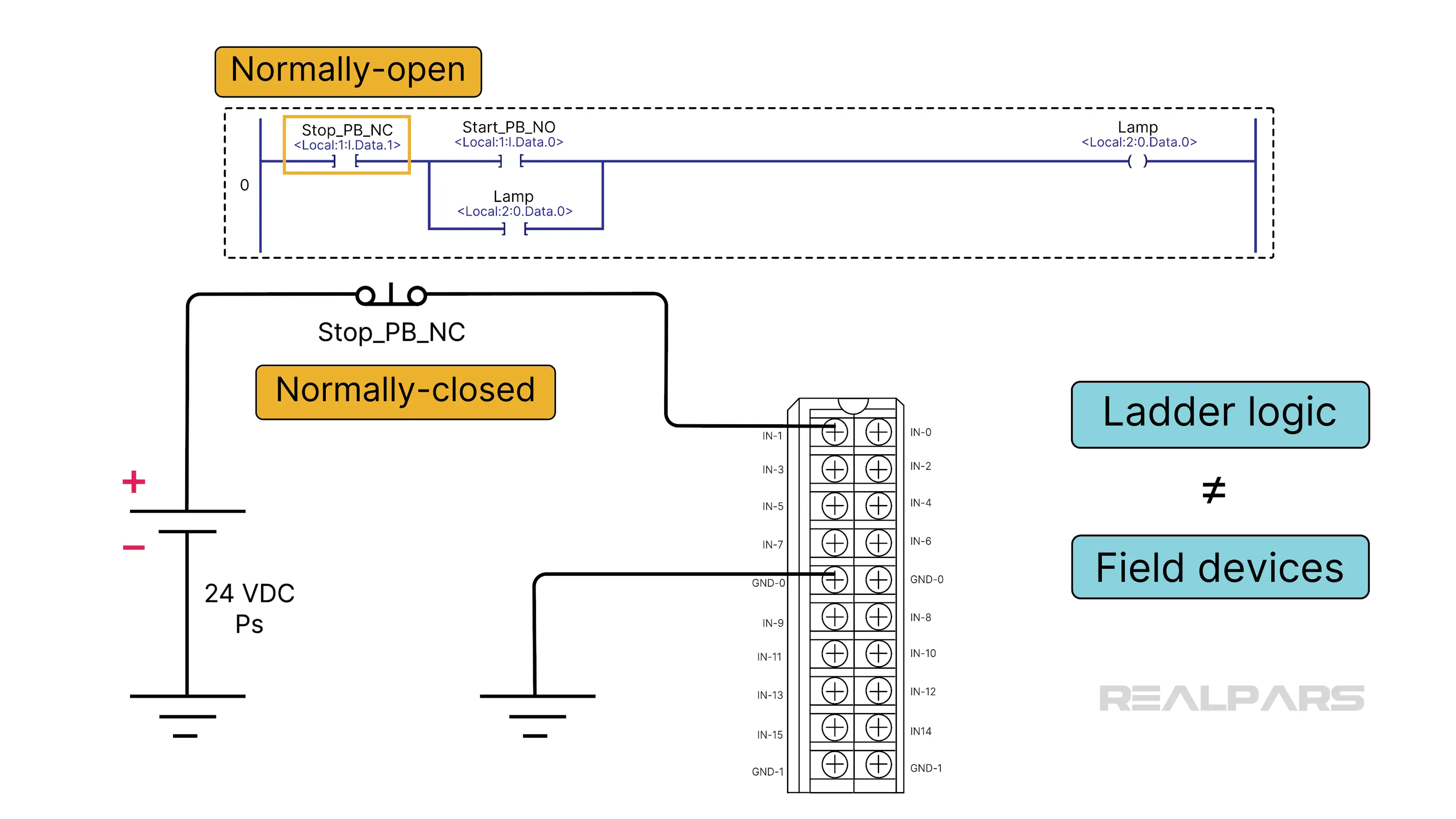
Programmers choose logic symbols based on the overall logic requirements of the program.
Alright…..let’s do some troubleshooting.
The first step in determining the source of any fault is understanding how the circuit operates normally and how it operates differently in the faulty condition.
The 1756-IB16 digital input module's LED input indicator panel is a powerful troubleshooting tool. It tells us whether each input is in a voltage ON or voltage OFF condition.
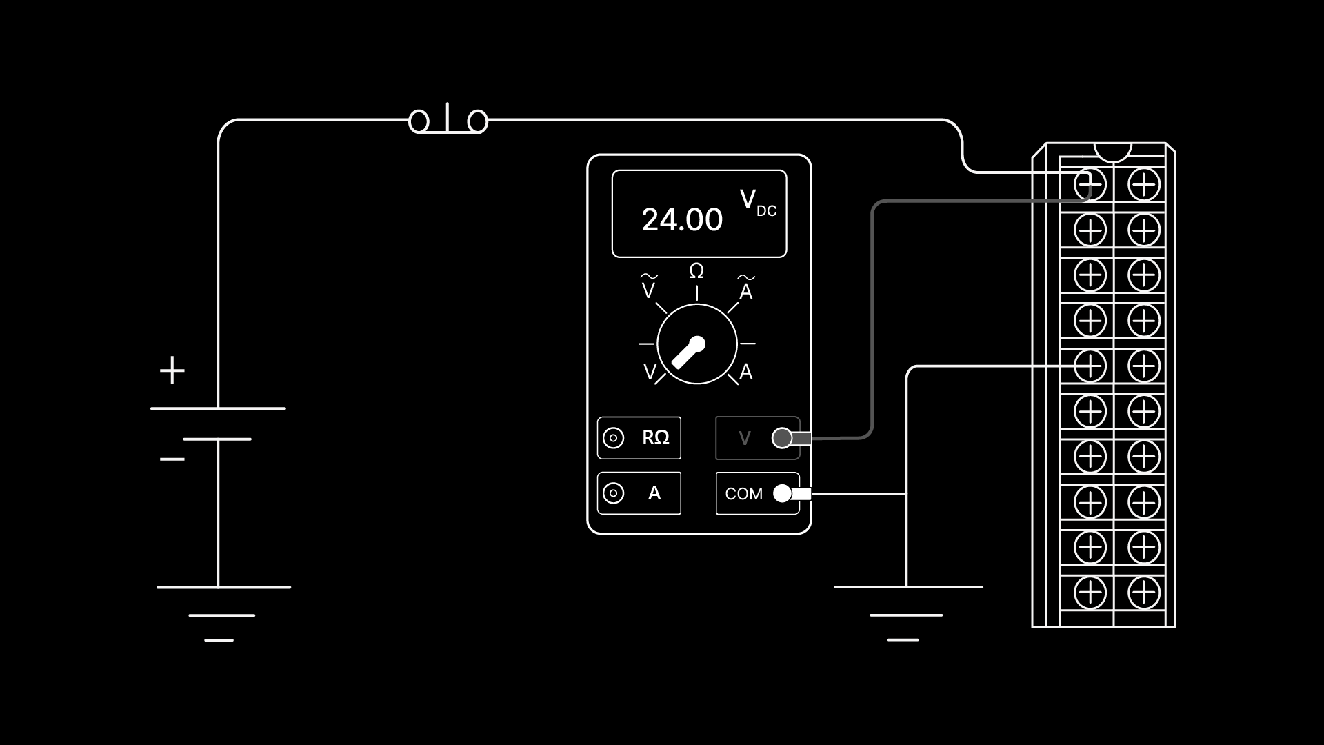
In our example, under normal conditions, the LED 1 should be on due to the condition of the Stop_PB_NC switch.
The normally open logic symbol Stop_PB_NC will be TRUE, as shown by the Green shading.
A DMM set as a voltmeter connected to terminal 1 of the module will measure +24 VDC.
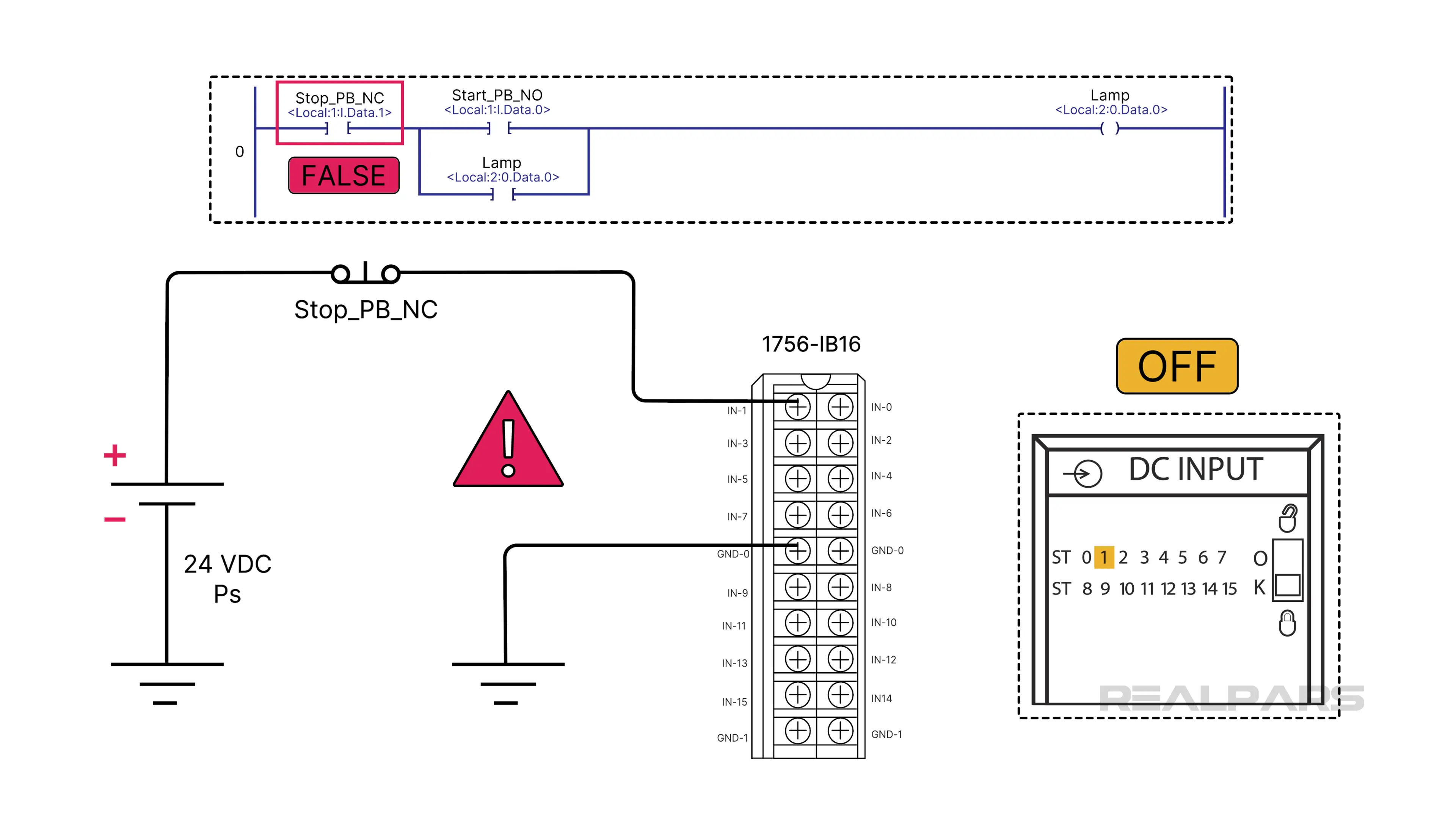
Let’s look at a fault condition example.
We observe that the Indicator LED 1 is off
And the normally open contact logic symbol Stop_PB_NC is FALSE, while it should be TRUE.
The next step is to list the possible fault causes.
The defective components could be:
- The field device switch Stop_PB_NC, or
- the 24VDC power supply, or
- the PLC input module
Or there might be a broken wire
Now it’s time to make some measurements with the digital multimer (DMM).
Here’s another tip for you.
Don't take any measurements if you don't know what you expect. Each measurement should lead to the subsequent measurement. Taking random measurements serves no purpose but to confuse you.
Let’s place the DMM set as a voltmeter at terminal 1 of the PLC input module.
If the voltmeter reads +24 volts DC, there are no broken wires, and the switch and power supply are working correctly. The suspected fault is the module.
If the voltmeter reads 0 volts DC, that explains why the LED “1” is off. We might have a defective switch, power supply, or a broken wire.
The next step is to move the voltmeter's red lead to the switch's module side. If the voltmeter reads +24 volts DC, there is likely a broken wire between the switch and terminal 1 of the input module.
If the voltmeter reads 0 volts DC, it could be a defective switch or power supply.
The next step is to move the voltmeter red lead to the power supply side of the switch.
If the voltmeter reads +24 volts DC, the power supply is fine, but the switch is likely defective.
At this stage, you could test the switch with an ohmmeter, but based on the voltage measurements, that test is not necessary.
Troubleshooting the output side
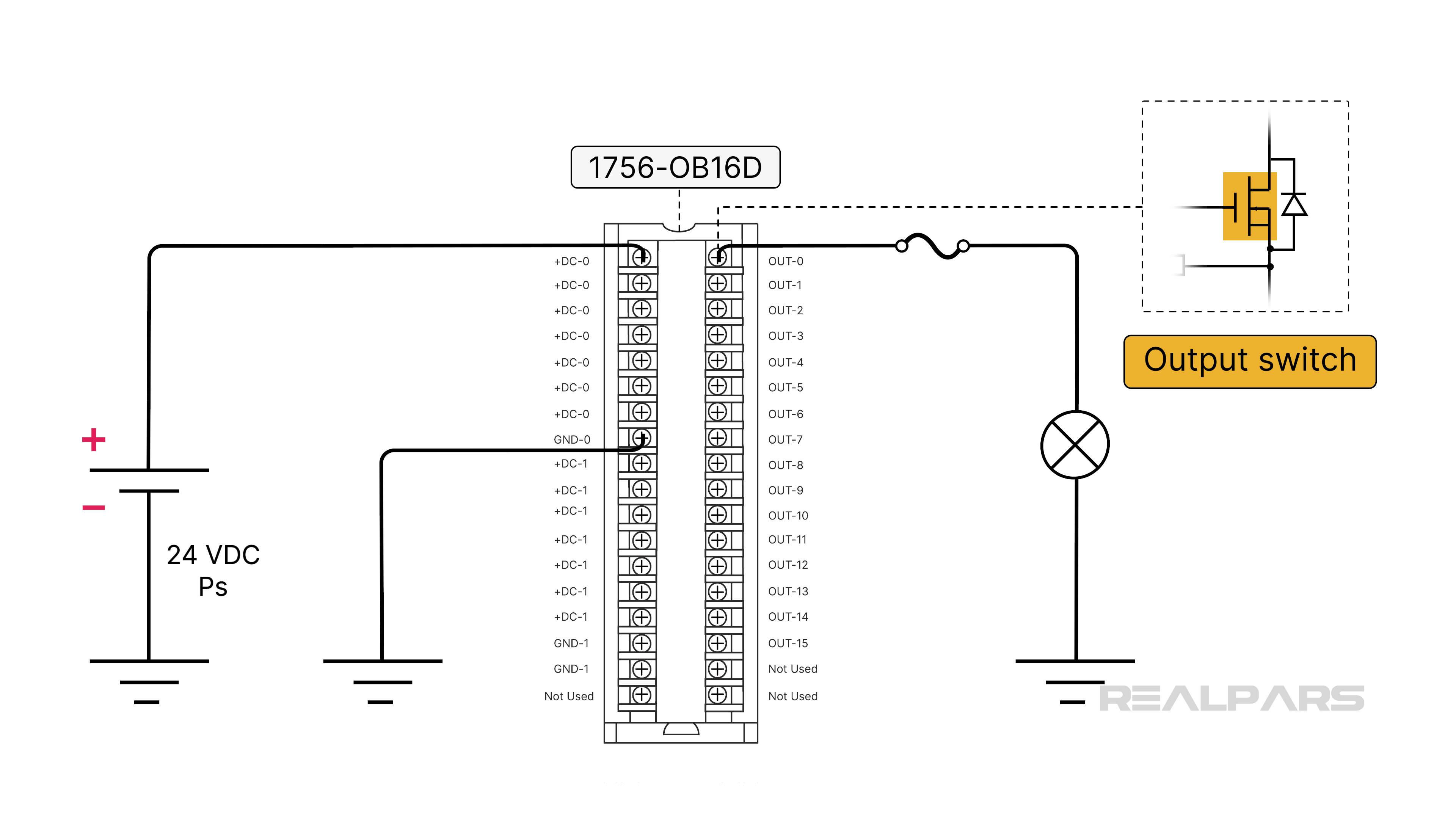
Okay…..let’s move on to the PLC's output side. We will connect a lamp to the output of an Allen Bradley 1756-OB16D digital Sourcing output module. A fuse protects the module from overload.
This output module type has a semiconductor output switch and can only handle a low current up to a maximum of 2 A.
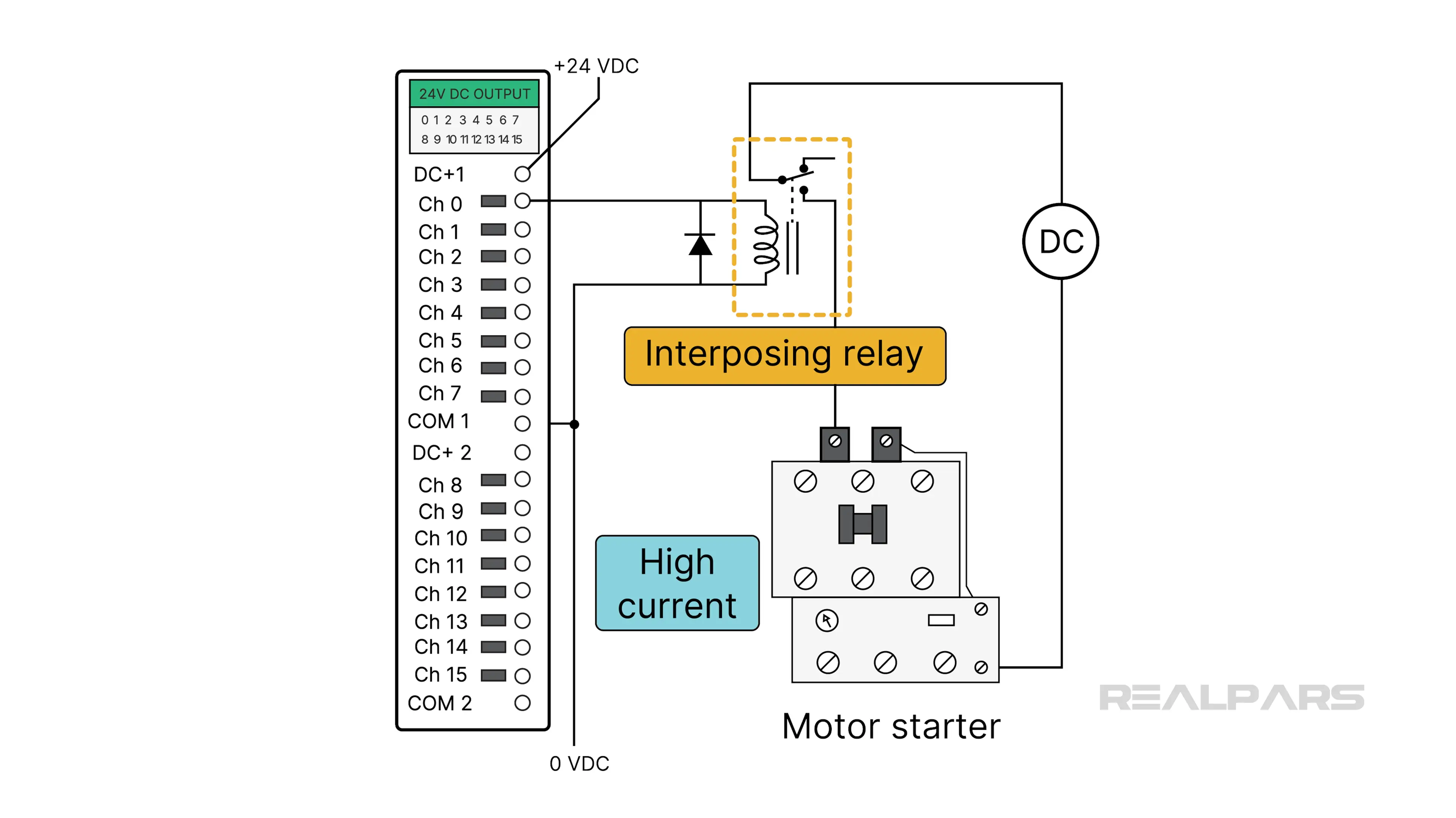
An interposing relay is often used to operate high-current loads such as motors.
If you want to know more about the Sinking and Sourcing PLC output module, I recommend the course PLC Hardware Fundamentals: Power, I/O Modules & Signals.
Again, we rely on Up-to-date drawings to verify wiring connections.
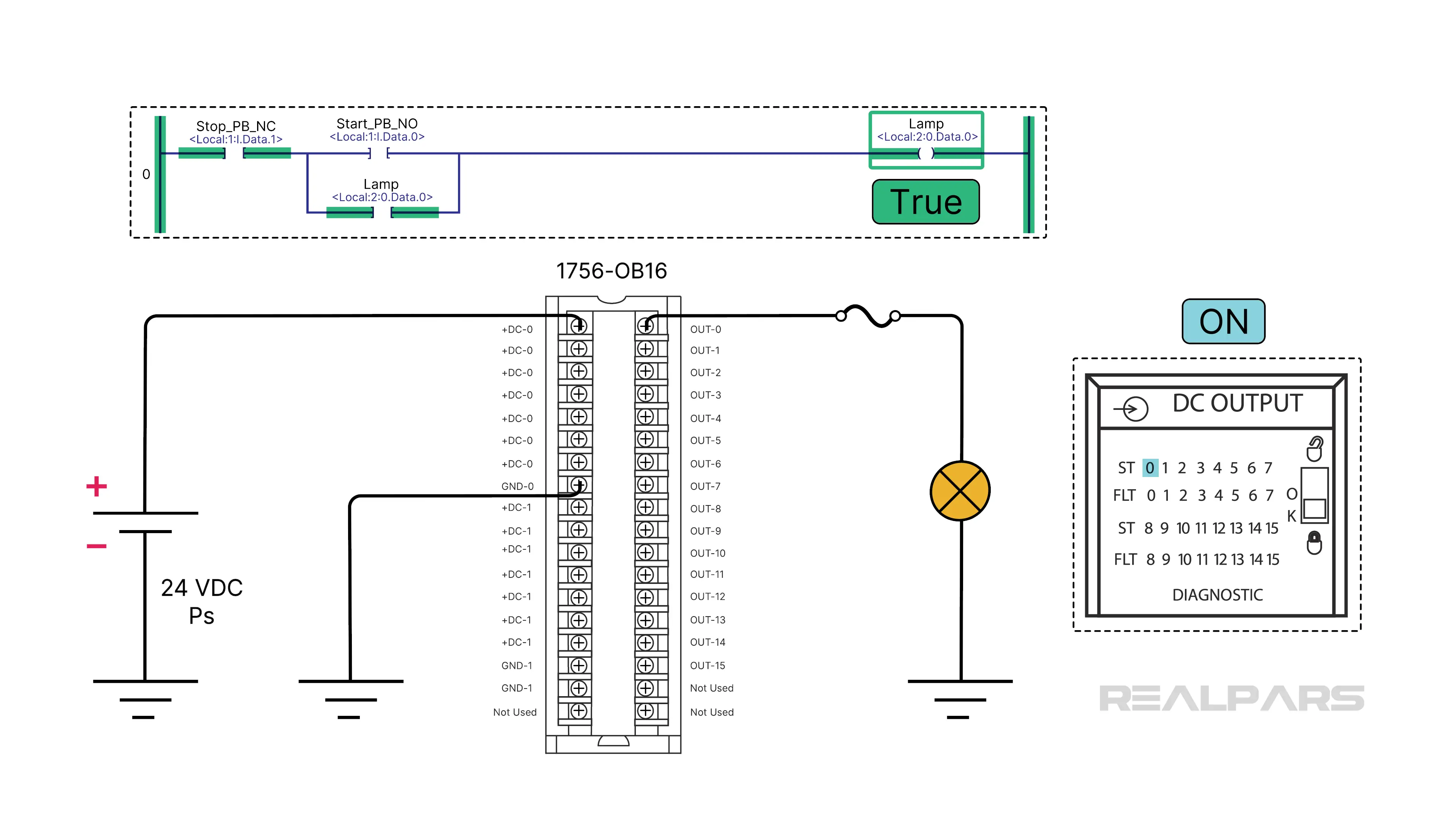
Let’s peek at the ladder logic program to see how the lamp is turned on.
The state of the Lamp coil symbol on Rung 0 determines the condition of the Lamp connected to the output module.
The 1756-ob16 digital output module has LED indicators that tell whether each output supplies voltage to energize the load.
So, under normal conditions, the LED “0” and the lamp should be on due to the TRUE condition of the program's Lamp coil symbol on Rung 0.
Let’s look at an example of a fault condition.
We observe that the indicator LED “0” is ON, but the lamp is OFF when it should be ON.
The next step is to list the possible fault causes.
The defective components could be:
- The fuse
- the lamp
- or the 24VDC power supply
Or there might be a broken wire
Now, it’s time to make some measurements with the digital multimer (or DMM).
We’ll start by placing the voltmeter between the fuse and the lamp.
Remember what we said earlier: don't make any measurements if you don't know what you expect. Each measurement should lead to the subsequent measurement. Taking random measurements serves no purpose but to confuse you.
If the voltmeter reads 0 volts, the fault is likely an open fuse. A broken wire on the output module side of the fuse may be the cause, but it is unlikely.
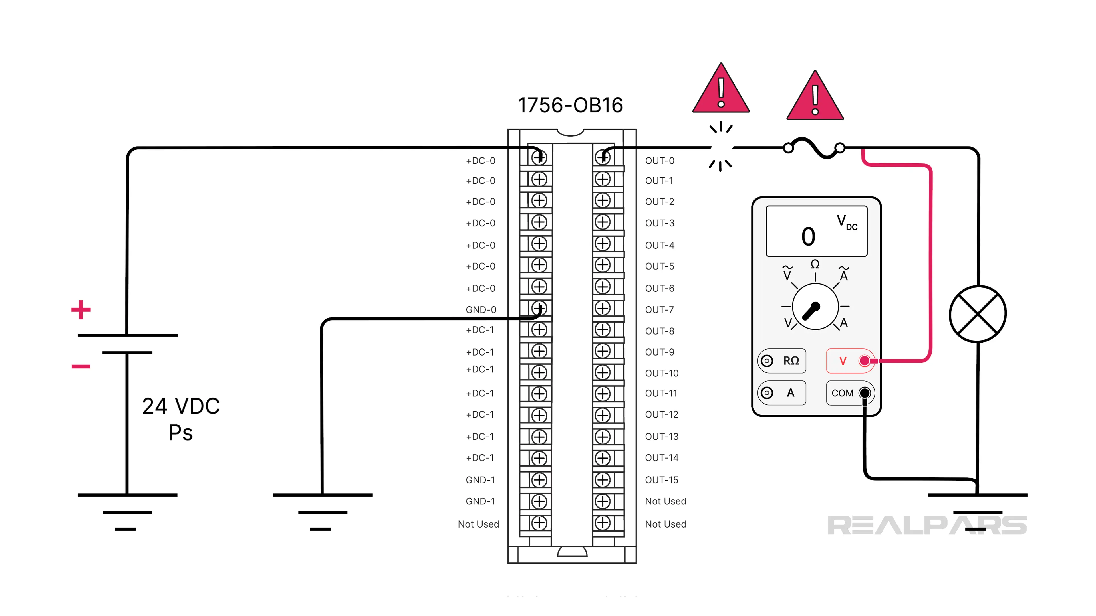
If the voltmeter reads 24VDC, the fault could be a defective lamp, a broken wire, or a corroded ground connection.
This might seem odd, but the next step is to move the voltmeter's red lead to the lamp's ground side.
If the voltmeter reads 24V DC, the lamp is fine, and the fault is either a broken wire between the lamp and the ground or a corroded ground connection.
If the voltmeter reads 0V DC, the lamp is defective.
Wrap-Up
Ok….let’s summarize what we’ve discussed………….
- PLC programs rarely are the cause of failures
- Field devices such as sensors and actuators are the most common cause of failures, followed by faulty PLC I/O modules
- Up-to-date drawings are essential to any testing and troubleshooting activities.
- PLC ladder logic symbols don’t always match the associated physical field device.
- Input and output module LED indicator panels are a powerful troubleshooting tool.
- Don't take any measurements if you don't know what you expect.
- Taking random measurements serves no purpose.
If you're a plant manager looking to train your maintenance team, visit realpars.com/business. Just add your contact information, and our team will quickly reach out to discuss how we can support your team's development.
As mentioned earlier, if you're interested in learning more about sinking and sourcing PLC input and output modules, I recommend checking out the course PLC Hardware Fundamentals: Power, I/O Modules & Signals.