When you want to turn on an electronic device like a TV or a refrigerator at home, you need to plug it into a socket. Depending on where you live, this socket supplies AC power, which is typically either 110 volts or 220 volts. For example, countries like the United States commonly use 110–120V AC, while many European and Asian countries use 220–240V AC. The same goes for the components inside a control panel. To turn on devices like PLCs inside a control panel, you usually need 24 volts DC power. This is different from the 110 or 220 volts AC power that we have at home. Devices like TVs or refrigerators work with 110 or 220 volts AC power, but industrial control devices such as PLCs usually work with 24 volts DC power. That’s why, if you open up almost any control panel, you’ll see a 24 volts DC power supply. These power supplies usually have inputs and outputs. They take the normal 110 or 220 volts AC power in the input and do some magic internally to turn that power into 24 volts DC power at the output. We take this 24 volts DC output and connect it to devices like PLCs inside a control panel to turn them on. Very simple.
What Is a Redundant Power Supply?
In some cases, we need to make sure that if the primary power supply fails, there is another backup power supply to power the PLC and the rest of the devices inside a control panel to prevent downtime. This is when we need to use a redundant power supply. This means that instead of only one 24 volts DC power supply, we will have two of them. This way, when one of them stops working for any reason, the other one can jump in to continue powering the devices inside the control panel. This is what we call a redundant power supply.
Real-Life Example: Redundant Power Supply in an Oil Refinery
In this blog post, you will learn how a redundant power supply works using a real-life practical example. I say a practical example because the redundant power supply we are about to explore is used in a real control panel inside one of the world’s largest oil refineries.
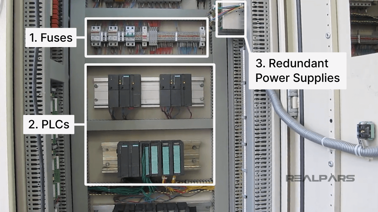
The picture below shows an overview of the inside of the example control panel. At the top of the panel, you can see the fuses. These fuses are simply there to break the circuit when the current goes out of range. In the middle, we have the PLCs. These are Siemens S7-300 PLCs with digital and analog inputs and outputs. And on the right side of the control panel, we have the redundant power supply, which will be the main focus of this blog.
By the way, if you want to learn how to program Siemens S7-300 PLCs, you can check out the course PLC Programming MADE EASY (Level 1).
Understanding the Connections
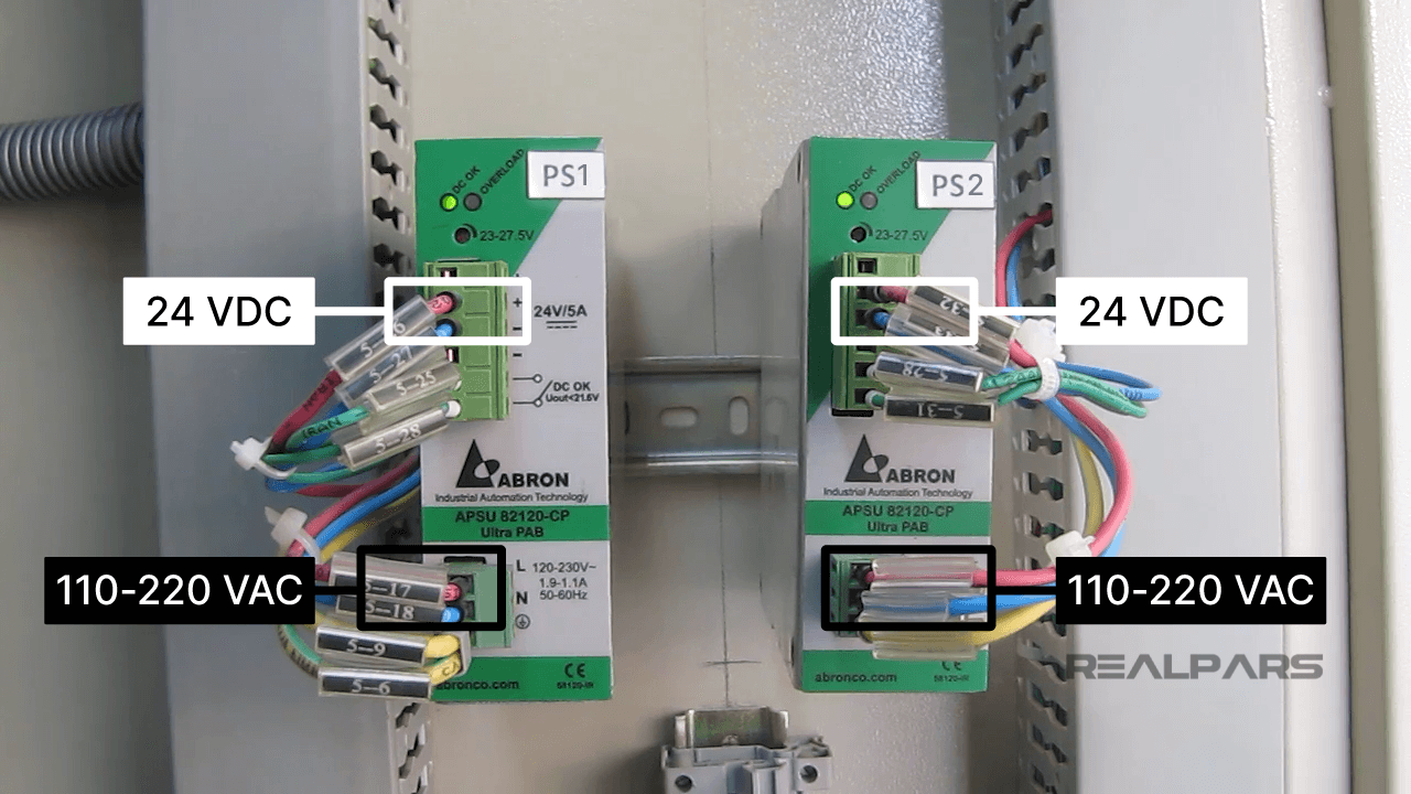
Ok, now let’s zoom in on the right side of this control panel where we have the redundant power supply.
On the front end of each of these redundant power supplies, we have two main terminals where a pair of red and blue wires are connected:
- The lower terminals are where we connect the incoming 110 to 220 volts AC power. This is the same normal electricity you use to turn on your TV or refrigerator at home.
- The upper terminals, as indicated in the picture, are where we have the 24 volts DC power output.
So, 110 or 220 volts AC power comes into the power supplies from one end, and then on the other end, we get a nice harmless 24 volts DC power. This 24 volts DC power is what we use to power the devices inside the control panel, including the PLC.
The Role of Ground Wires
As you can see, we also have a pair of yellow wires connected to both power supplies. These are ground wires. The ground wires connect the power supplies to the grounding system of the control panel. By doing this, if there is a current leakage, instead of harming personnel or damaging any device in the control panel, it will safely be redirected to the ground.
Monitoring with Open Contacts
Inside each of these power supplies, there is also a simple open contact. The way this open contact works is that it remains open when the power supply is working properly. However, when it fails, for example, if the output voltage drops below 24 VDC (like 21 VDC), this contact closes.
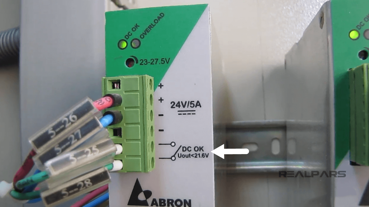
So, this contact acts as an indicator, telling us when the power supply is not working well. Now, we can simply use this open contact and connect it to a PLC input. Then, in the PLC program, we can write simple logic so that when this contact closes, a PLC output will be activated. We can then use this output as an alarm or just a simple indicator in the HMI. Again, if you want to start learning PLC programming, I recommend checking the course PLC Programming MADE EASY (Level 1), and if you want to learn about HMI design and configurations, you can check out these courses.
Ok, the two green wires you see in the picture above are connected to the two ends of the open contact. These will be connected on the other end to the PLC input.
What 24V/5A Means
On the front end of each power supply, you also see "24V/5A." We already know that "24V" indicates the 24 VDC power output of the power supply. As I explained before, these power supplies receive 110 to 220 volts AC power as input and deliver 24 volts DC power as output. But what does "5A" mean? This simply means that the maximum capacity of each power supply is 5 amperes. The more devices we have inside the control panel, the more current output we need from the power supply. For example, for a small control panel, like the one for the elevator in your building, you may see a 24 volts power supply with a 2 amperes current output. For a medium-sized control panel, like the one we have here, a power supply with a 5 amperes current output can work fine. For bigger control panels, you may see power supplies with 10 or 20 amperes current output. You may also see a combination of 5 amperes and 2 amperes power supplies in some cases. It all depends on the number of devices we need to power inside the control panel and the design. Usually, the more devices inside the control panel and the bigger the panel is, the more current output we need for the power supply. That is why when you are ordering power supplies, they usually give you options like 1A, 2A, 5A, 10A, or 20A, and so on.
How Redundancy Works
Ok, now that you understand all the wiring and the rest of the details on the front of each power supply, let’s go inside the redundant power supply system and see how it actually works.
The picture below is a simple diagram of this redundant power supply unit. Each one of these power supplies can handle the full load. This means that both of these power supplies are strong enough to independently power the entire control panel.
PS1 works as the “primary” power supply, and PS2 works as a “backup.” The primary power supply is the one actively delivering the power, while the backup power supply is on standby and ready to take over if the primary fails. But how does this happen? This is where the D1 and D2 diodes come into play.
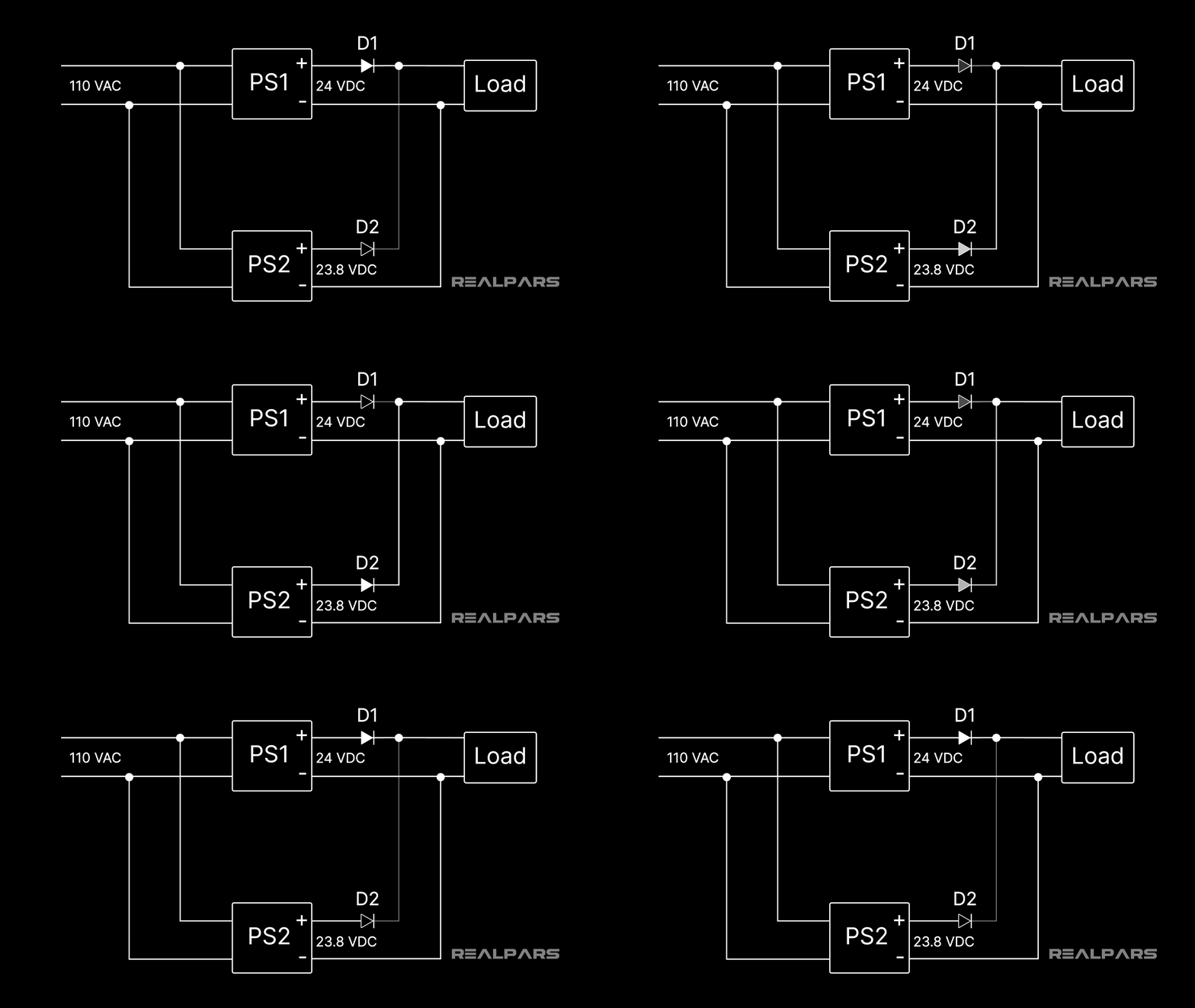
As you can see in the diagram above, the output voltage of PS1 is slightly higher than PS2. PS1 has 24 VDC as the output voltage, and PS2 has 23.8 VDC. With this setup, D1 allows the current from PS1 to flow into the load. The load here represents all the devices we have inside the control panel. At the same time, since PS2’s output is slightly lower (23.8 VDC), D2 won’t allow the current from this power supply to flow into the system. So, in normal operation mode, PS1 powers the control panel, and PS2 stays as the backup. Now, what happens when PS1, the primary power supply, fails?
When PS1 fails, either by being shut down or by its voltage dropping below PS2’s, D1 blocks the current output of this power supply. At the same time, since the output voltage of PS2 is now higher than PS1, D2 allows the current from PS2 to flow into the load, and this is how the power stays uninterrupted for the control panel.
Now, what happens when we fix or replace PS1 later on? When we do that, the output voltage of PS1 goes back to 24 VDC, and since this is higher than the output voltage of PS2, which is 23.8 VDC, D1 allows the current of PS1 to flow into the load again, and D2 blocks the current output of PS2. This way, PS1 goes back to its role as the primary power supply, and PS2 remains as the backup.
If you are a plant manager or maintenance manager and want to train your team of technicians or engineers on industrial automation topics like PLC programming, PLC troubleshooting, industrial sensors, and actuators, check out this link for RealPars Business Membership and fill in the form.
Can Normal Power Supplies Be Used as Redundant?
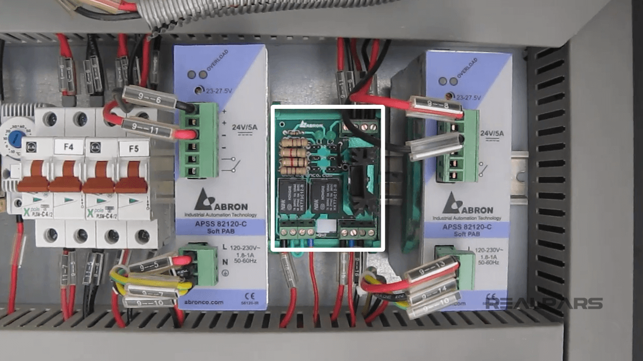
Ok, so now you know how a redundant power supply works. But you may ask, can we also use two normal power supplies as redundant? The answer is yes, but for this to work, we need to add a simple diode module on the output. This is what you can see in the picture below. Here, instead of a set of redundant power supplies, we have used two normal power supplies and added a simple diode module on the output. This setup works exactly the same as the redundant power supply you learned about above. The only difference is that, in the previous example, the diodes were built internally, but with this one, the diodes are external.
Adjusting Output Voltage
After adding the external diode module, we also need to do an extra adjustment to the power supply output. As mentioned before, for the diode to allow only the current of one power supply and block the other, we need to make sure that the output voltage of the backup power supply is slightly lower than the primary one. But how can we do that? Should we open up the power supplies and adjust the circuits? The answer is no. Fortunately, for these power supplies, we can easily do this without opening the units, and it’s so simple that even your grandma could do it. Here’s how:
You see the small hole on the front of each power supply above the upper terminal, highlighted in the picture below? You can take a small flat-head screwdriver and turn the screw to adjust the output voltage. If you turn the screw clockwise, you can increase the output voltage, and if you turn it counterclockwise, you can decrease it. For this case, you can adjust the primary power supply output voltage to 24 VDC and the backup to 23.8 VDC. If you’re wondering, it doesn’t matter which one you designate as primary or backup. That’s up to you to choose.
Now, you may say, "Ok, I’ve turned the screw, but how do I know the output voltage of each power supply? There’s no indicator here!" Yes, you’re right, but to do this, you can simply use a multimeter and measure the output voltage for each of these power supplies to make sure they are both set to the exact output voltage you need for them to work as a redundant power supply unit.
If you want to learn more about working with multimeters and instrument calibration in general, be sure to check out the course Temperature Transmitters: Calibration, Principles & Industry Applications by Ted Mortenson.
Conclusion
Redundant power supplies are simple to use and understand. They are useful when you want to make sure the 24 VDC for your control panel is never interrupted and there’s no downtime for your industrial operation. To set this up, you can use a set of redundant power supplies with built-in diodes or simply use two normal power supplies and add a diode module to it.
So, using redundant power supplies is one of the ways you can reduce downtime as a plant manager or maintenance manager. But, as I mentioned before, another effective way to reduce downtime is to train your team. This is what you can do using RealPars Business Membership. Fill in the form, and our team will get back to you.
And if you want to learn more, here is a list of courses we mentioned in this blog post:
- Course #1: PLC Programming MADE EASY (Level 1)
- Course #2: HMI Configuration and Development
- Course #3: Temperature Transmitters: Calibration, Principles & Industry Applications
That’s it! I hope you learned something useful and practical from this blog post. If you did, make sure to share this with a friend or colleague. They will thank you for it.

