What Is Studio 5000 Logix Emulate?

Rockwell Automation’s Studio 5000 is a modular Automation Engineering and Design environment.
The most common Studio 5000 module used in the industry is Logix Designer. This module is used to configure and program the Allen Bradley Logix 5000 family of PLCs, including CompactLogix and ControlLogix PLCs.
Another useful module is Logix Emulate. In this article, I’ll explain what Studio 5000 Logix Emulate is and how you can use it to test your Logix Designer projects.
Before we get into this article If you want to learn more about how to program Logix 5000 controllers using Studio 5000 Logix Designer, check out our Learn Logix course series. You can learn more about Learn Logix using this link.
Ok, Let’s start by talking about what Studio 5000 Logix Emulate is.
Studio 5000 Logix Emulate
Studio 5000 Logix Emulate is a software application that lets you emulate a Logix 5000 controller on your computer.
Studio 5000 Logix Emulate is used to test and debug Studio 5000 Logix Designer in a controlled environment without investing in PLC hardware. Since Studio 5000 Logix Emulate is a controlled environment, you can do some things that are not possible with a physical Logix 5000 controller such as modifying the speed of execution, simulating discrete I/O, and adding breakpoints to the project.
Now that we know what’s possible with Studio 5000 Logix Emulate, let’s set up an emulated controller and see how we can use Studio 5000 Logix Emulate to test Studio 5000 Logix Designer projects.
Set up Studio 5000 Logix Emulate
On my computer, I launch Studio 5000 Logix Emulate.
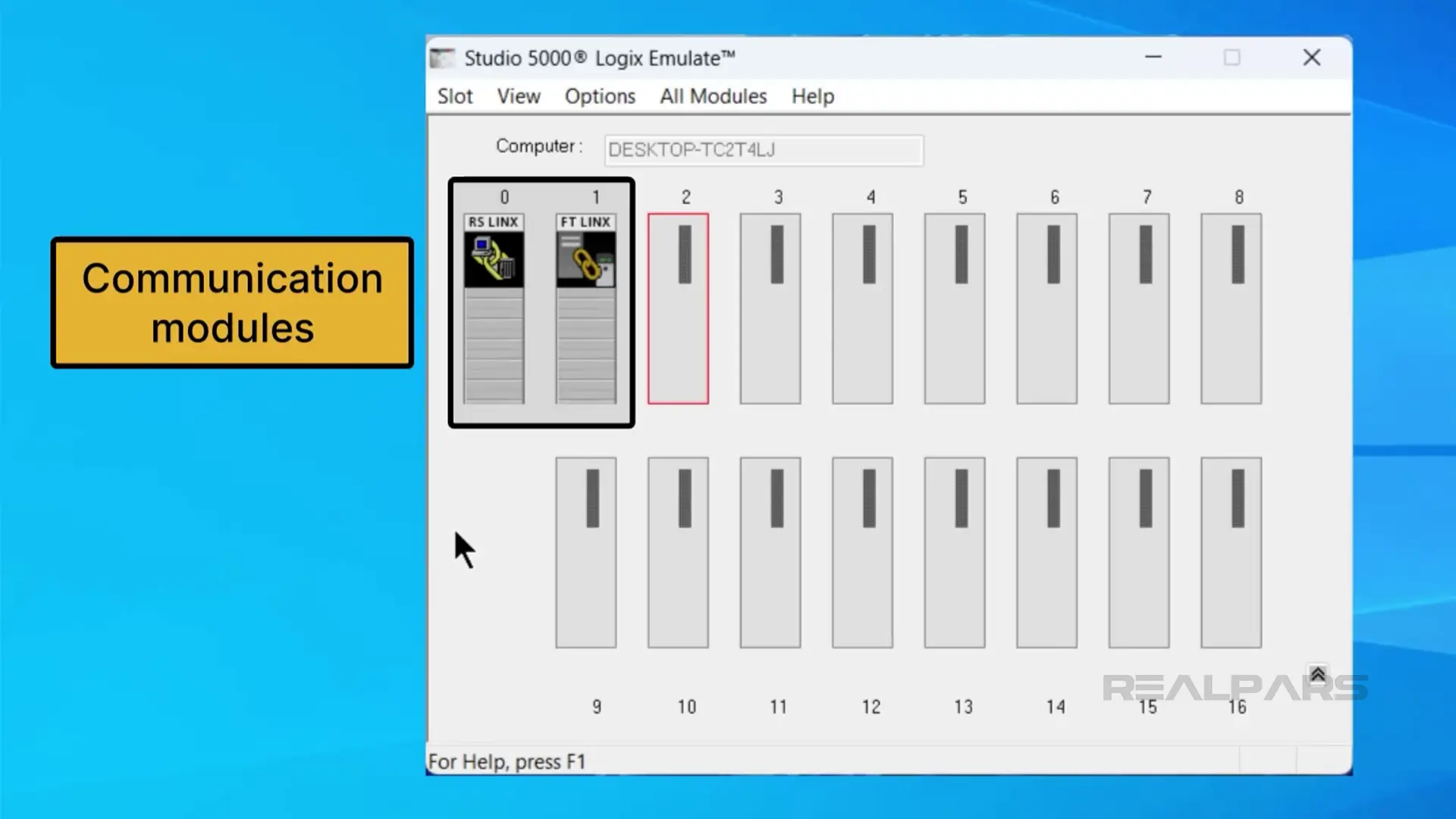
The application opens and by default, there are two modules in the virtual chassis. These are communication modules that are used to establish communication between the Logix Emulate and Logix Designer applications.
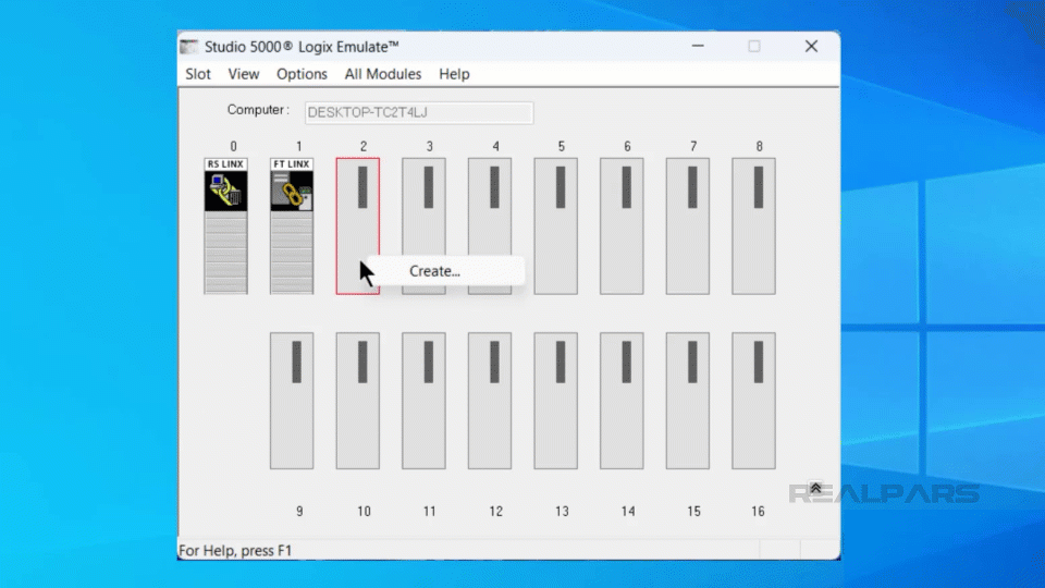
To add a controller to a chassis, I can right-click on an empty slot and select Create
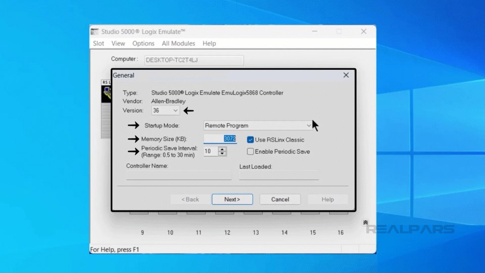
In the dialog that opens, I specify that I want to create an Emulate 5570 controller and click OK.
In the General and System dialogs, you can configure some properties of the emulated controller. For this demo, I will accept the default values and click Next, then Finish to create the emulated controller.
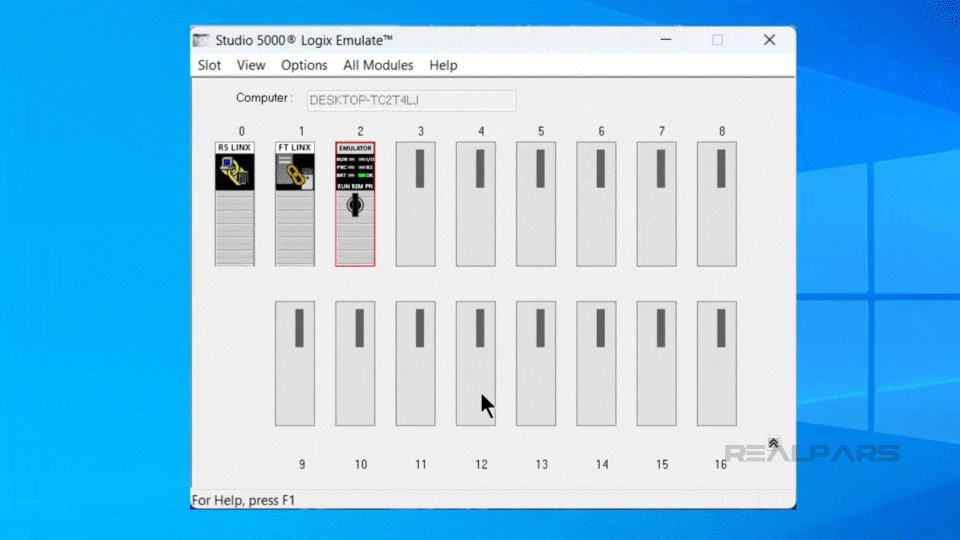
An emulated controller has been added to the chassis.
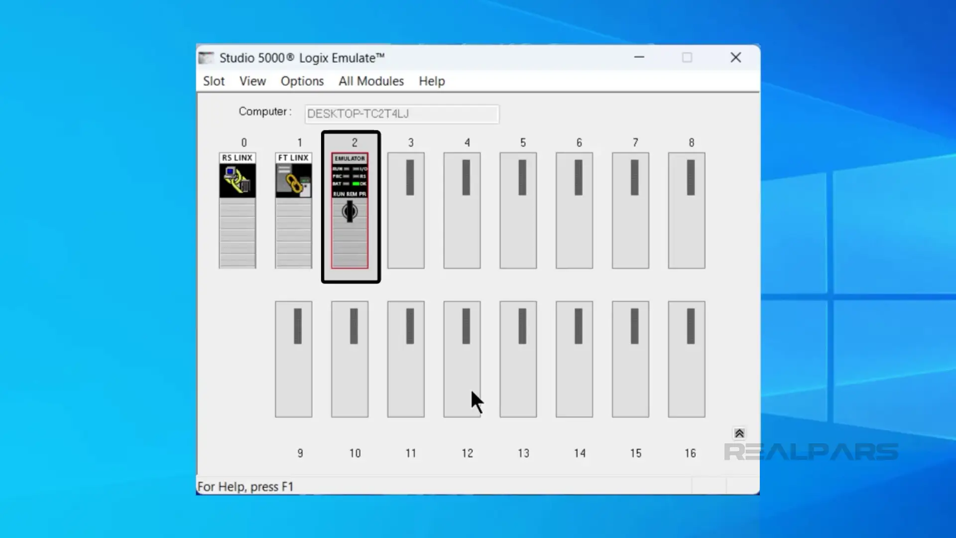
As well as adding controllers to the virtual chassis, we can add simulated IO modules. Go ahead and add a 1789-SIM IO module to the chassis as shown here.
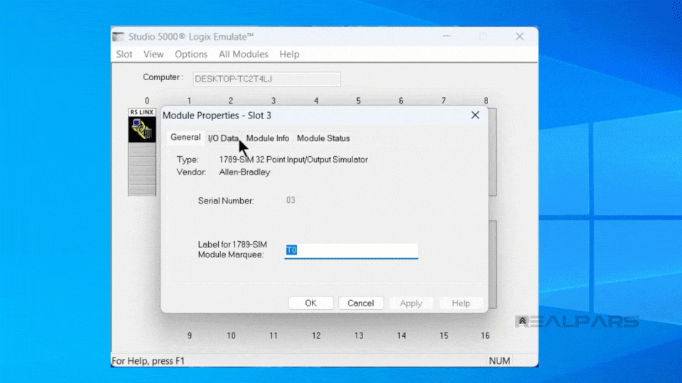
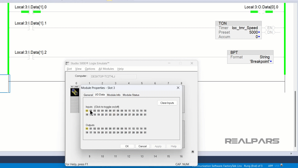
To simulate an input, right-click on the module and select properties.
In the properties dialog, switch to the I/O data tab and click on any input to toggle it on or off.
Now that our emulated controller and IO are set up, let’s switch to Studio 5000 Logix Designer to see how we can test projects using Logix Emulate.
Testing with Studio 5000 Logix Emulate
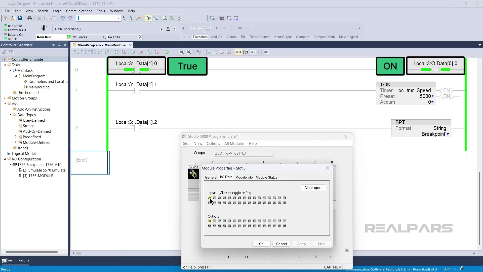
In Studio 5000 Logix Designer, I can download the project and go online with a Logix Emulate controller like a normal Logix 5000 controller as shown here.
.gif)
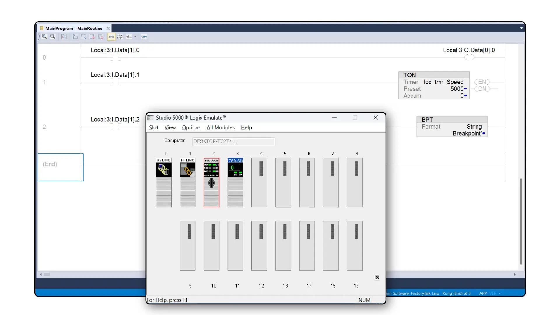
Once I’m online with the controller, I can monitor the MainRoutine and simulate the first input of the emulated IO module becoming True.
As expected, we see the input become True in Studio 5000 Logix Designer and the first output is turned on. We can see that the is output has turned on in Logix Emulate too.
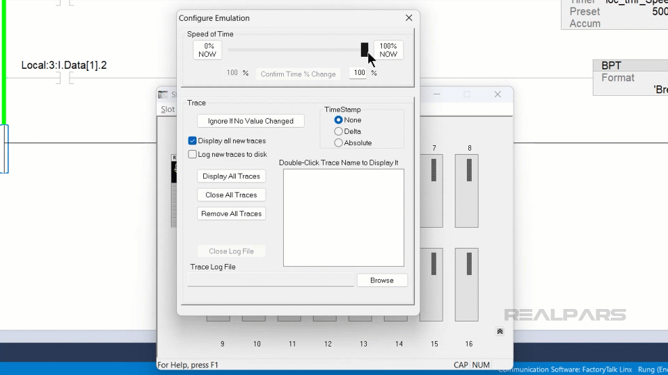
To make it easier to view the execution of logic, Studio 5000 Logix Emulate includes a Speed of Time feature. Using this feature, you can slow down the execution of logic in an emulated controller to a percent of real time.
To access this feature, right click on the emulated controller and select configure emulation.
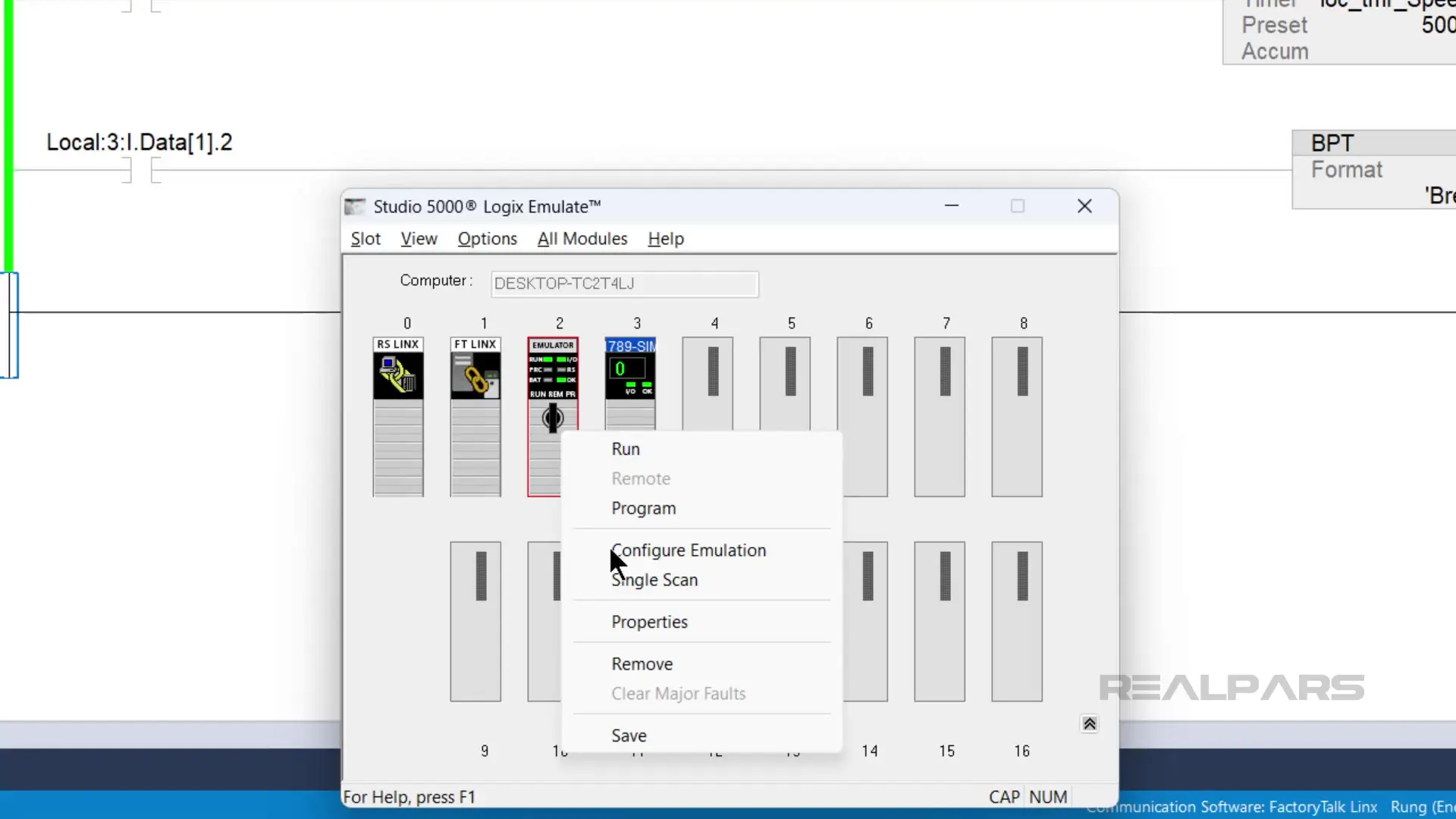
Then use the slider to adjust the Speed of Time to around 50% and click on Confirm % Time Change.
In Logix Designer, I can simulate the second input of the simulated IO Module becoming True and see that the timer is incrementing at about fifty percent of real time.
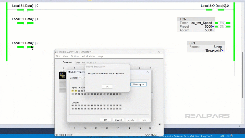
Finally, I can simulate the third input becoming True to activate the breakpoint instruction.
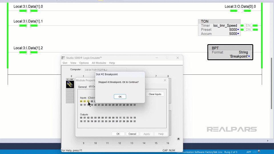
When the rung-in condition for the breakpoint instruction becomes True, the execution of the routine is paused. This allows me to inspect the logic being executed at a snapshot in time and, potentially, trace some values when the breakpoint is activated.
I can dismiss the prompt to resume execution of the program.
Wrap-Up
In this article, I explained what Studio 5000 Logix Emulate is and how you can use Studio 5000 Logix Emulate to test your Logix Designer projects. Also, we learned how to set up an emulated controller, how to simulate IO using a simulated IO module, how to slow down the execution of logic in an emulated controller, and how to pause execution using Breakpoints.
As mentioned before, If you want to learn more about how to program Logix 5000 controllers using Studio 5000 Logix Designer, check out our Learn Logix course series.
Each course in this series teaches you a specific aspect of programming and testing Logix Designer projects and working with Logix 5000 hardware. By the end of the series, you will be a confident and competent PLC programmer specializing in programming Allen Bradley Logix 5000 PLCs.
Also, if you're a plant manager or a maintenance manager and want to train your team of and technicians and engineers and reduce your downtime, be sure to check RealPars Business Membership and fill in the form.
Here’s a list of the courses mentioned in this blog post:
Course #1: Learn Logix 1: The Logix 5000 Product Line
Course #2: Learn Logix 2: A Complete Guide to CompactLogix Systems
Course #3: Learn Logix 3: A Complete Guide to ControlLogix Systems
Course #4: Learn Logix 4: Basic PLC Programming with Studio 5000 Logix Designer
Frequently asked questions
Learn from Industry Experts
With a 7-day trial, then €35/month