

This article is unlike any of the articles we’ve done before. We’re going to delve into the world of panel drawings! This is an exceptionally useful weapon to have in your armory, as it not only helps you to build panels and understand the inner workings of them, but they help to troubleshoot problems if they occur later. If you can follow a panel wiring diagram, you will be able to find the root cause of any problem in a panel! Learn how to follow an electrical panel wiring diagram below.
Let’s go back and have a look at the control panel, and try and figure out some of the connections by following a wiring diagram.
As I’ve mentioned in the previous articles, this is a control panel that is used for a system that turns wastewater into clean water.
It is a 2-door control panel on the front of which we have some switches that are connected to the PLC inputs and outputs.
We are going to look at these switches and try and figure out the wiring behind them, as you may be curious as to how these switches are wired to the PLC!
Let us first identify our push buttons; we have the Mute Buzzer push button, the ESD Reset push button and the Emergency Stop push button.
Try to remember these from the previous RealPars article about Reviewing the basics of an electrical control panel, and see if we can find any of these items in the electrical drawings.
Electrical Panel Wiring Diagram Software
All the wiring that you see in the panel is done based on the wiring diagram.
This is what we draw using AutoCAD Electrical.
Each page of this wiring diagram shows the exact wiring for different sections of this control panel.

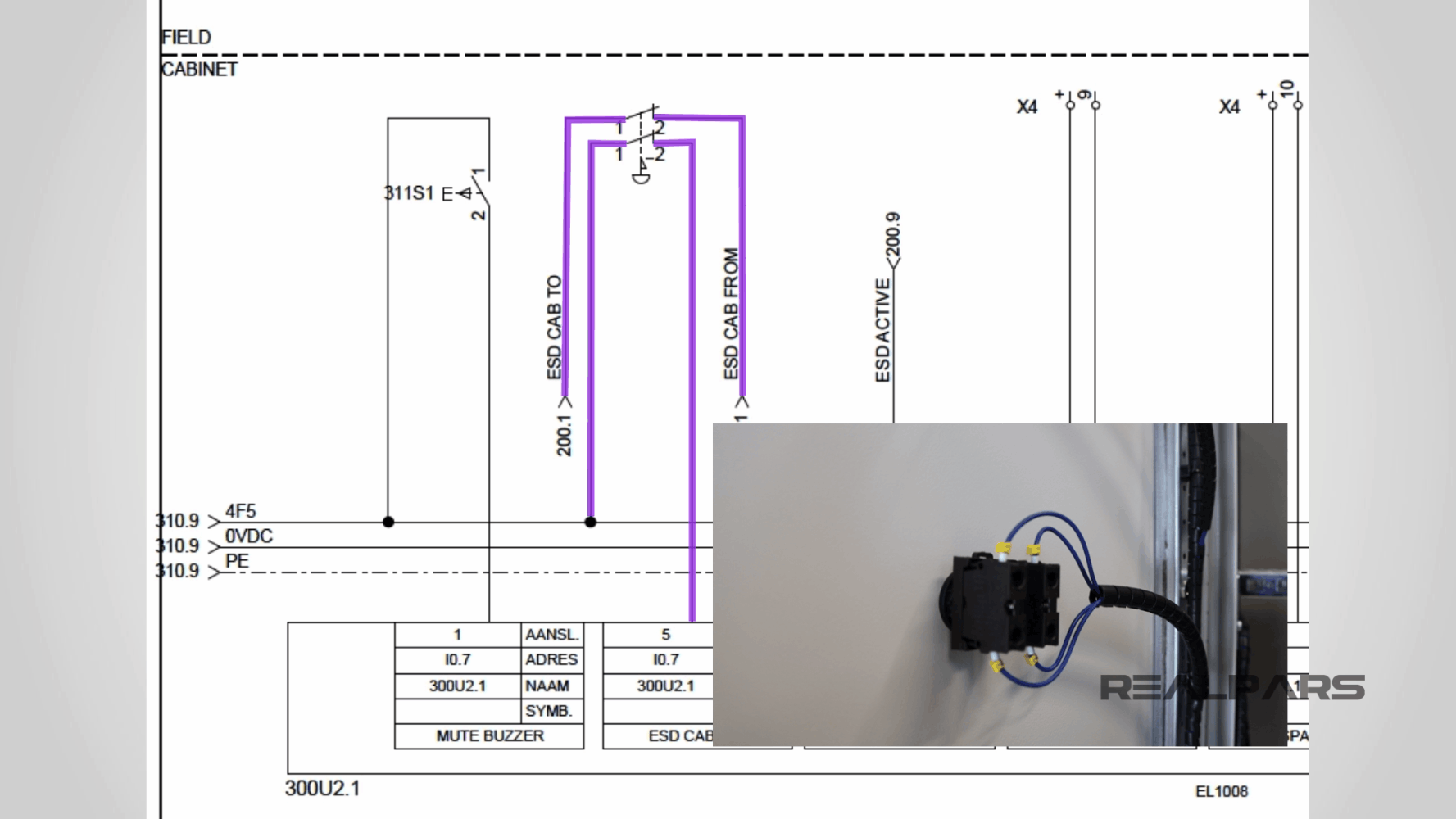
For instance, for our Emergency Stop push button, it shows the wiring for this switch. You see that there are four wires that are connected to this switch.
These are wires on the back of the Emergency Stop push button, on the rear of the door.
Each of these wires has a tag number. The tags for these two wires are 1 and on the other end is 2.
Panel Wiring Diagram Pages and Sections
For the upper wire, it shows that there is a wire that comes from page 200 section 1.
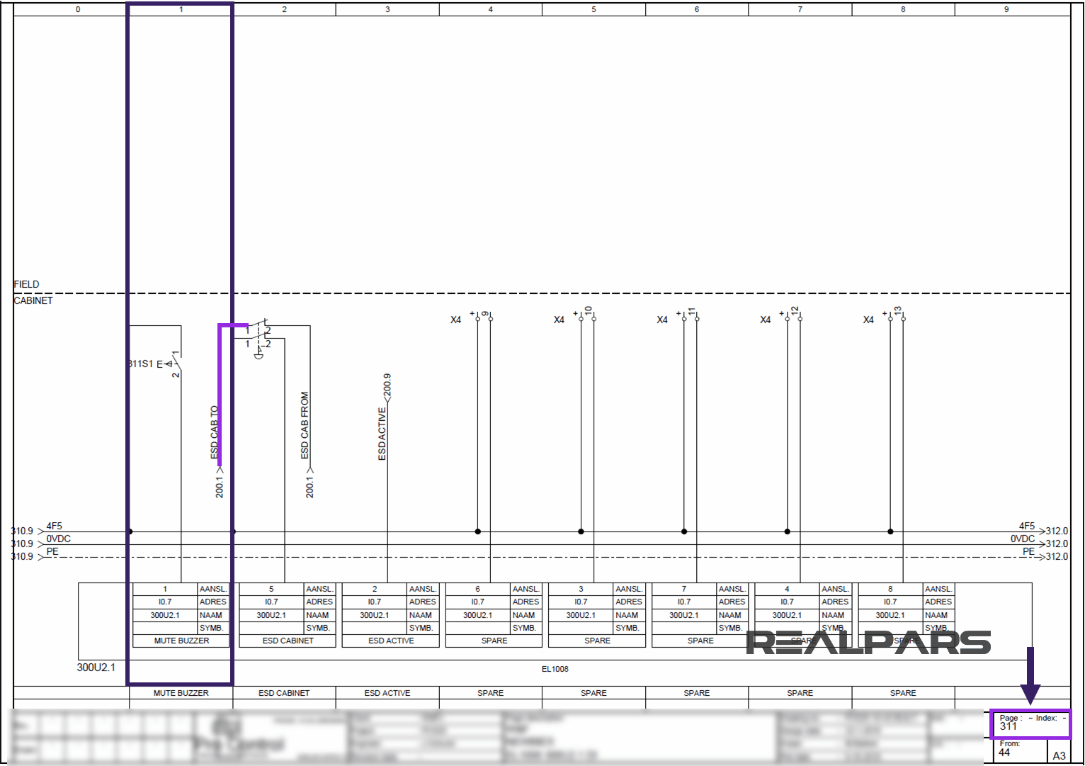
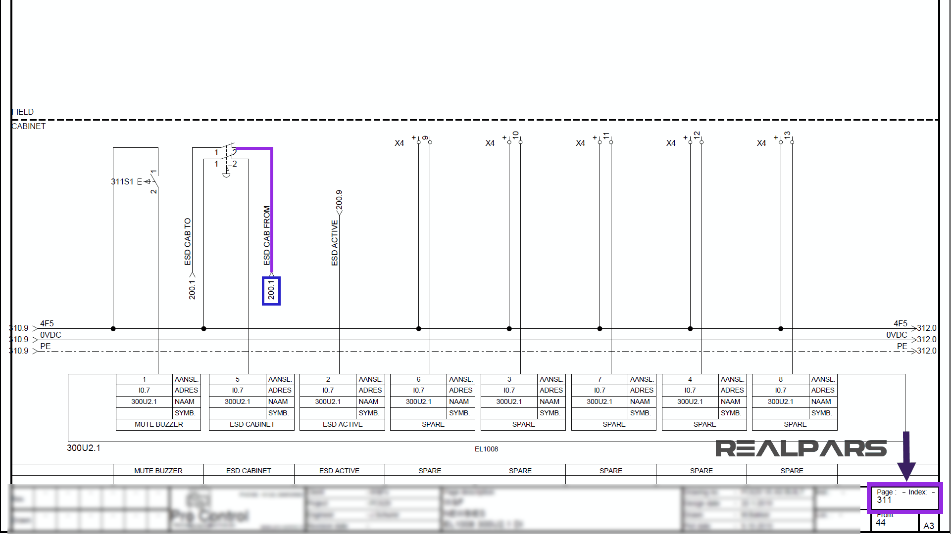
We have the page numbers at the bottom of each page. For example, it shows that we are on page 311.

The wire comes from page 200 section 1.
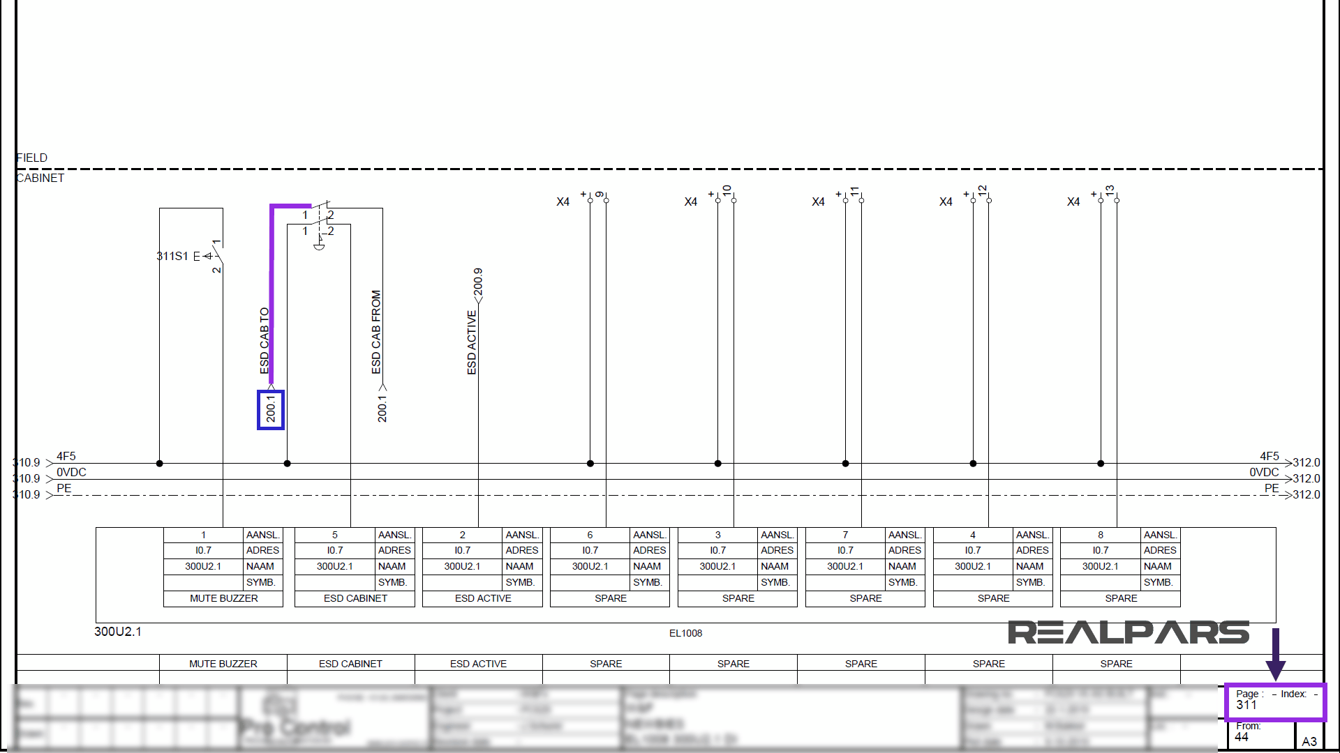
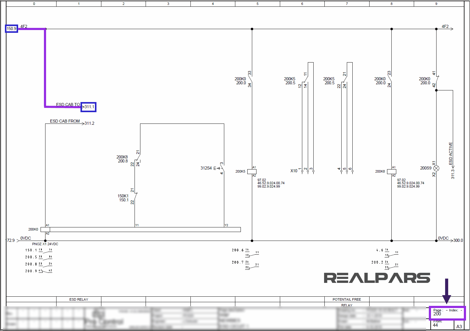
So I’ll go to page 200 and then section 1 and this is where this wire comes from.
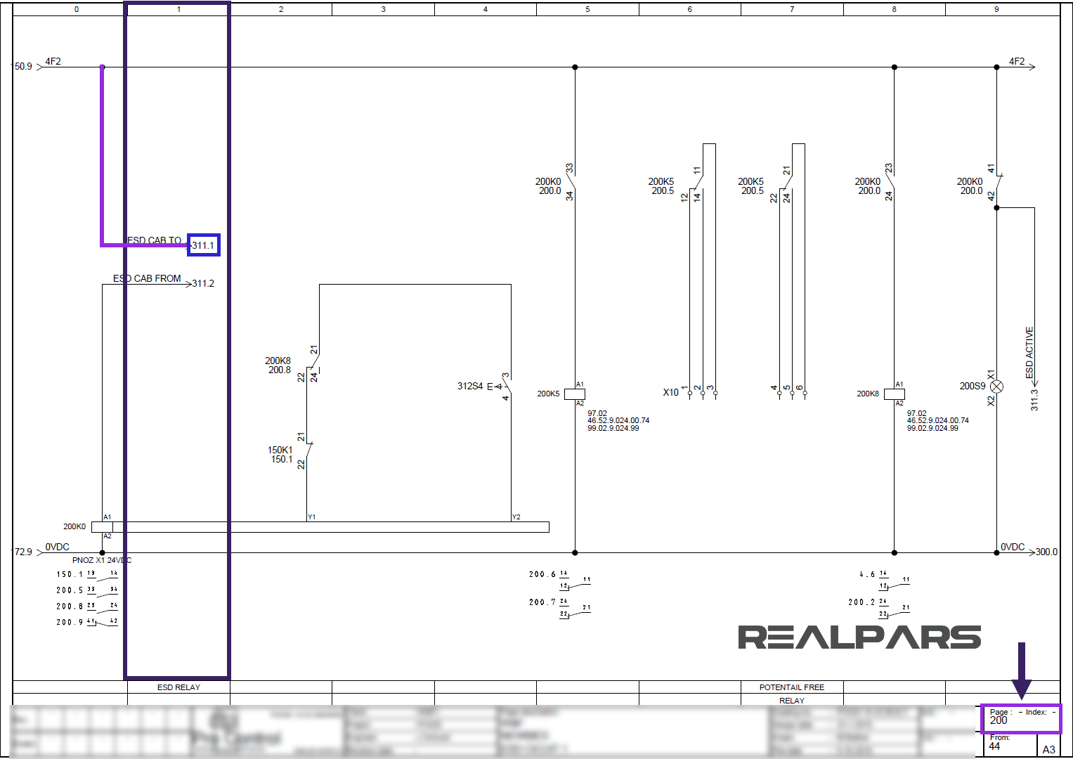
As you can see it says this wire goes to page 311 section 1, which is the page and the section that we were looking at. So if I go to page 311 and section 1, I can see this wire.
Now if I go back to page 200, you see that this wire comes from page 150 section 9.
So if I go to page 150 and section 9, I can see where this wire comes from.
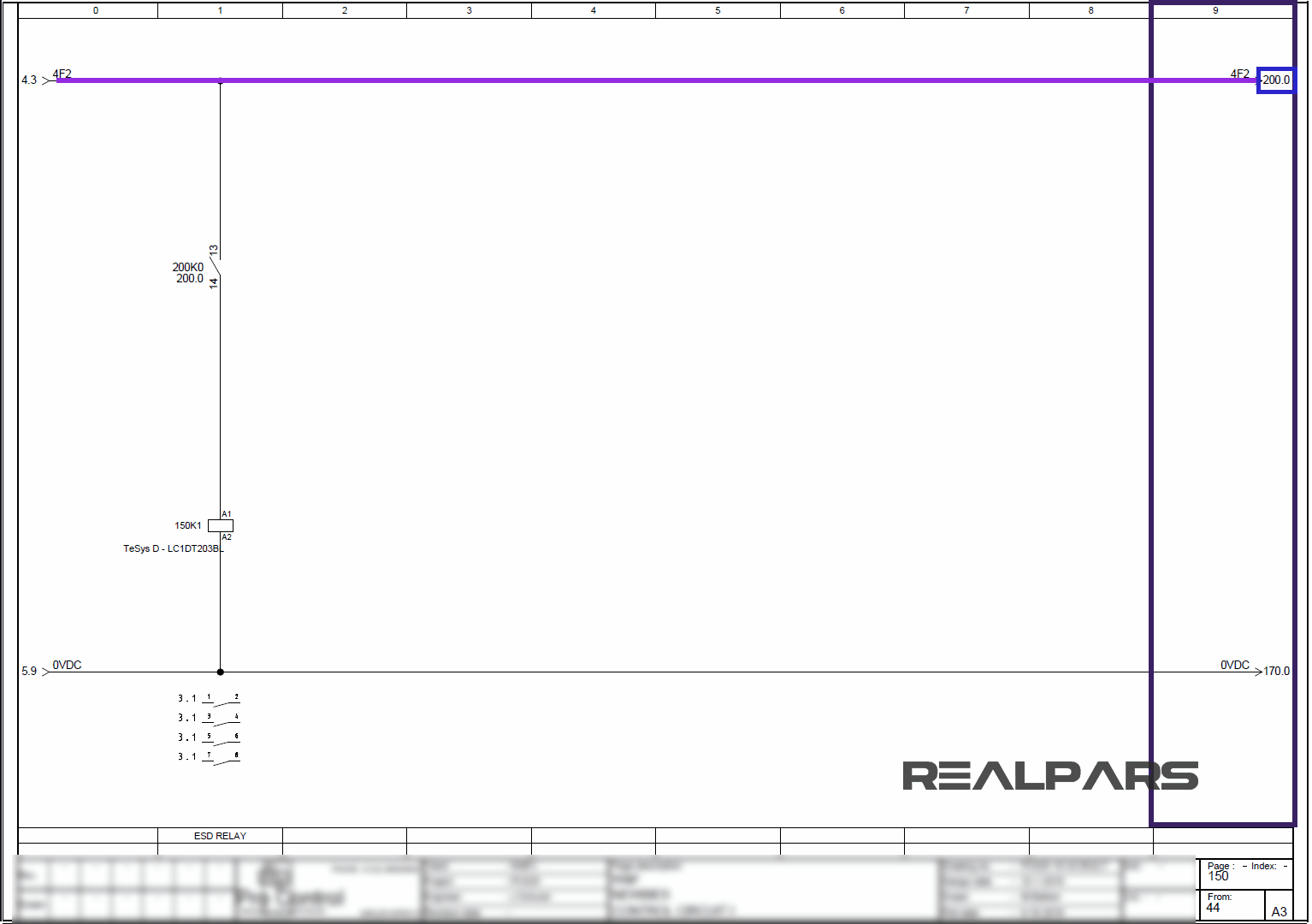
You can see that it says the wire goes to page 200 section 0 which is where we just came from.
So this wire goes to page 200 section 0.
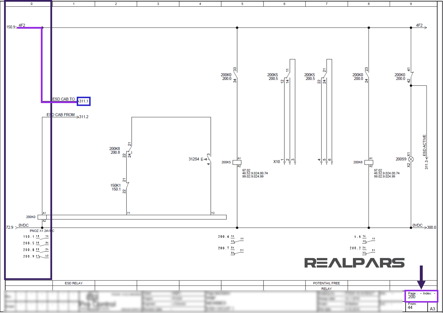
Then it goes to page 311 section 1.
This is page 311 section 1 and this is the wire that is connected to the Emergency Stop push button.
The same goes for the other wires as well. For example, this wire comes from page 310 section 9.

This one comes from page 200 section 1 again.
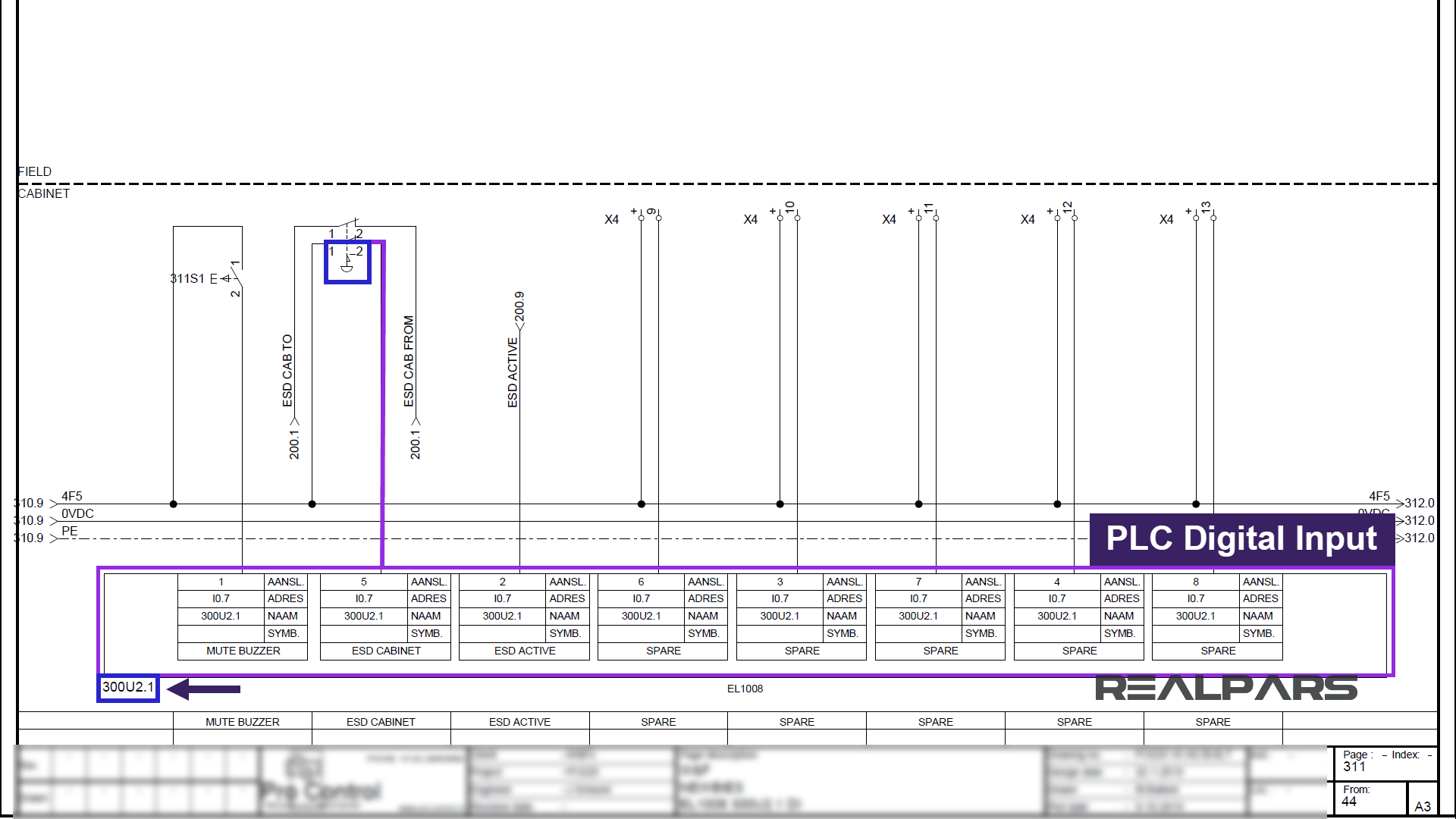
And this one connects to our PLC digital input. And the tag for the PLC input is 300U2.1.
Wire Tag
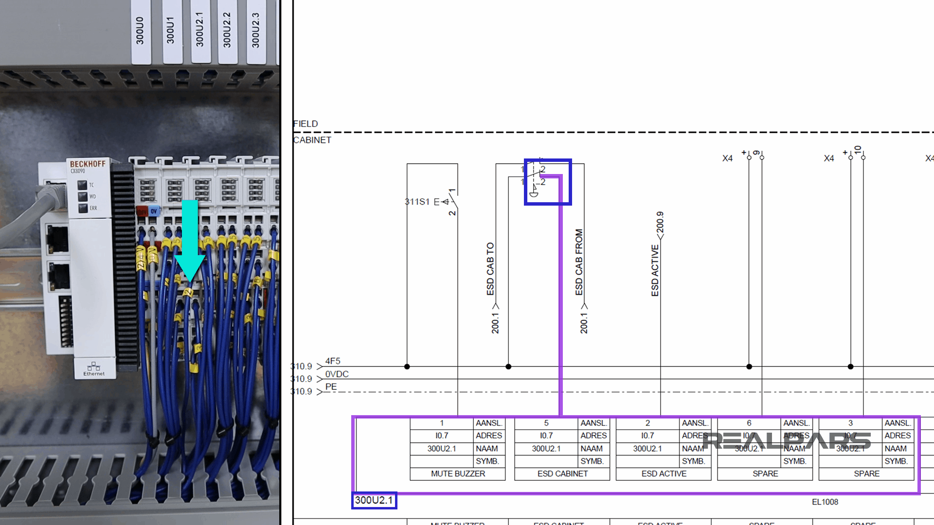
In the back of the Emergency Stop push button, you see that we have four wires, just as what we have on the wiring diagram.
Two wires are tagged as “1” and two wires are tagged as “2”.
Based on the diagram, one of these wires with the tag 2 goes to the PLC digital input.
Let’s see if we can find this wire.
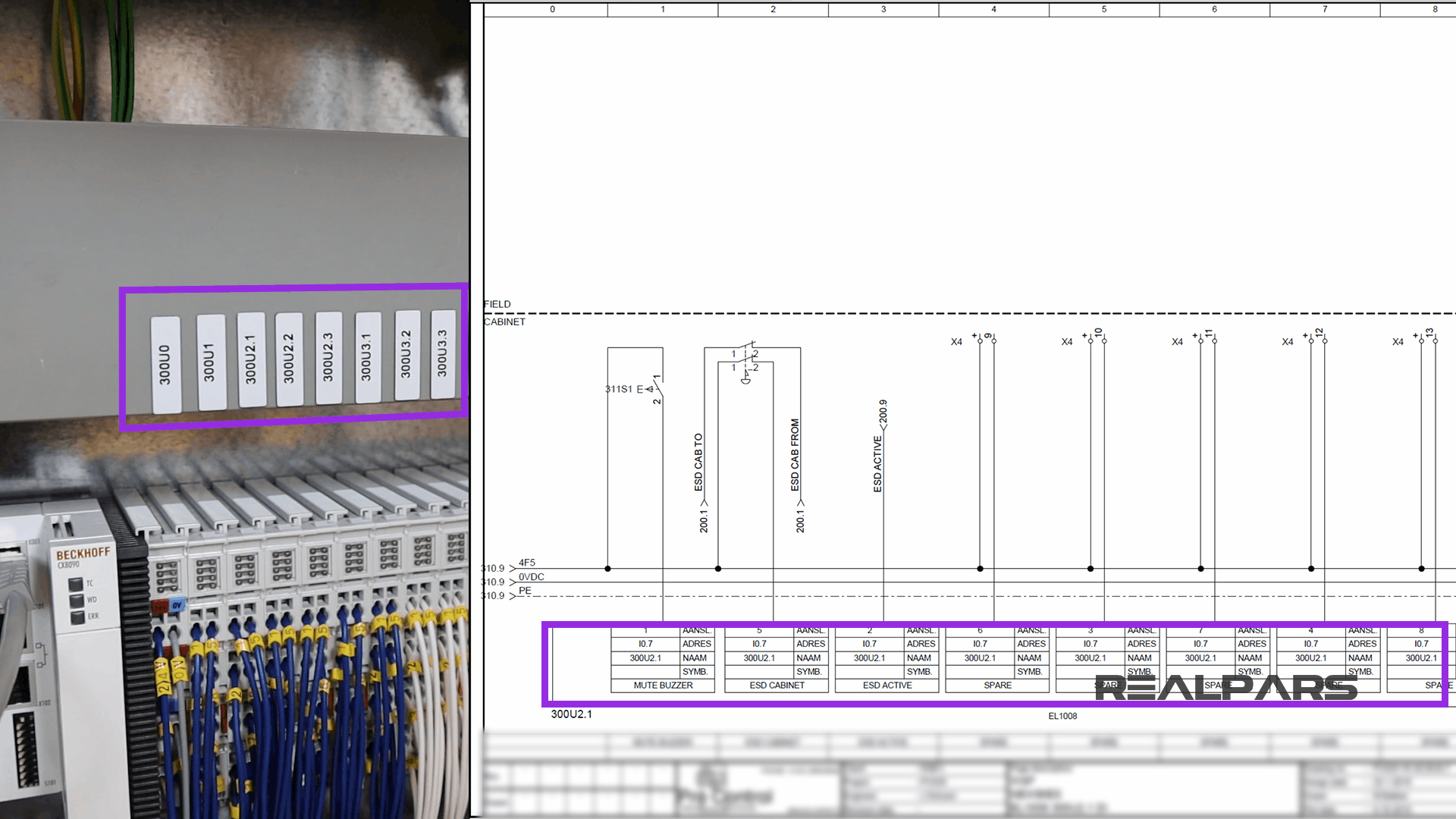
In the wiring diagram, it says the tag for the PLC input that the push button is connected to is 300U2.1.
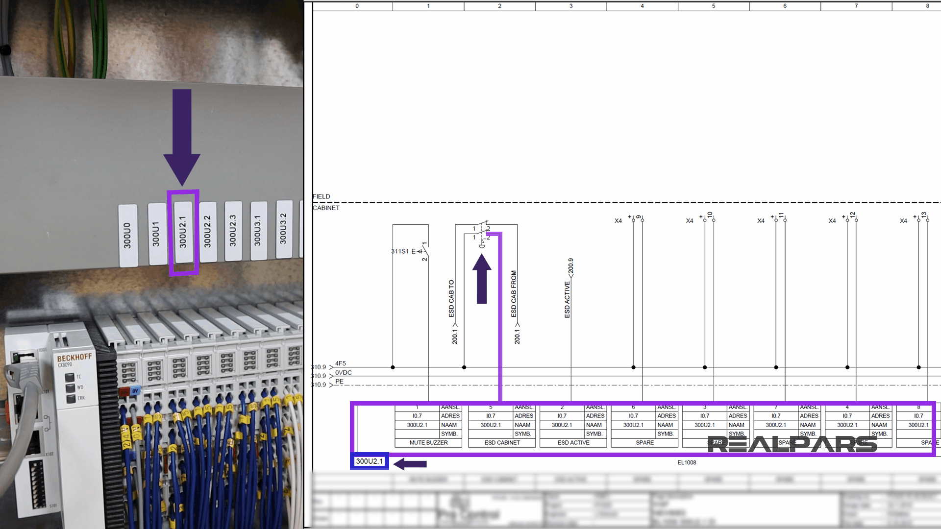
These are the tags for the PLC inputs and outputs.
Now based on the diagram I need to look for a wire that is tagged as 2. So in the image below, you’ll see the wire that I am looking for.
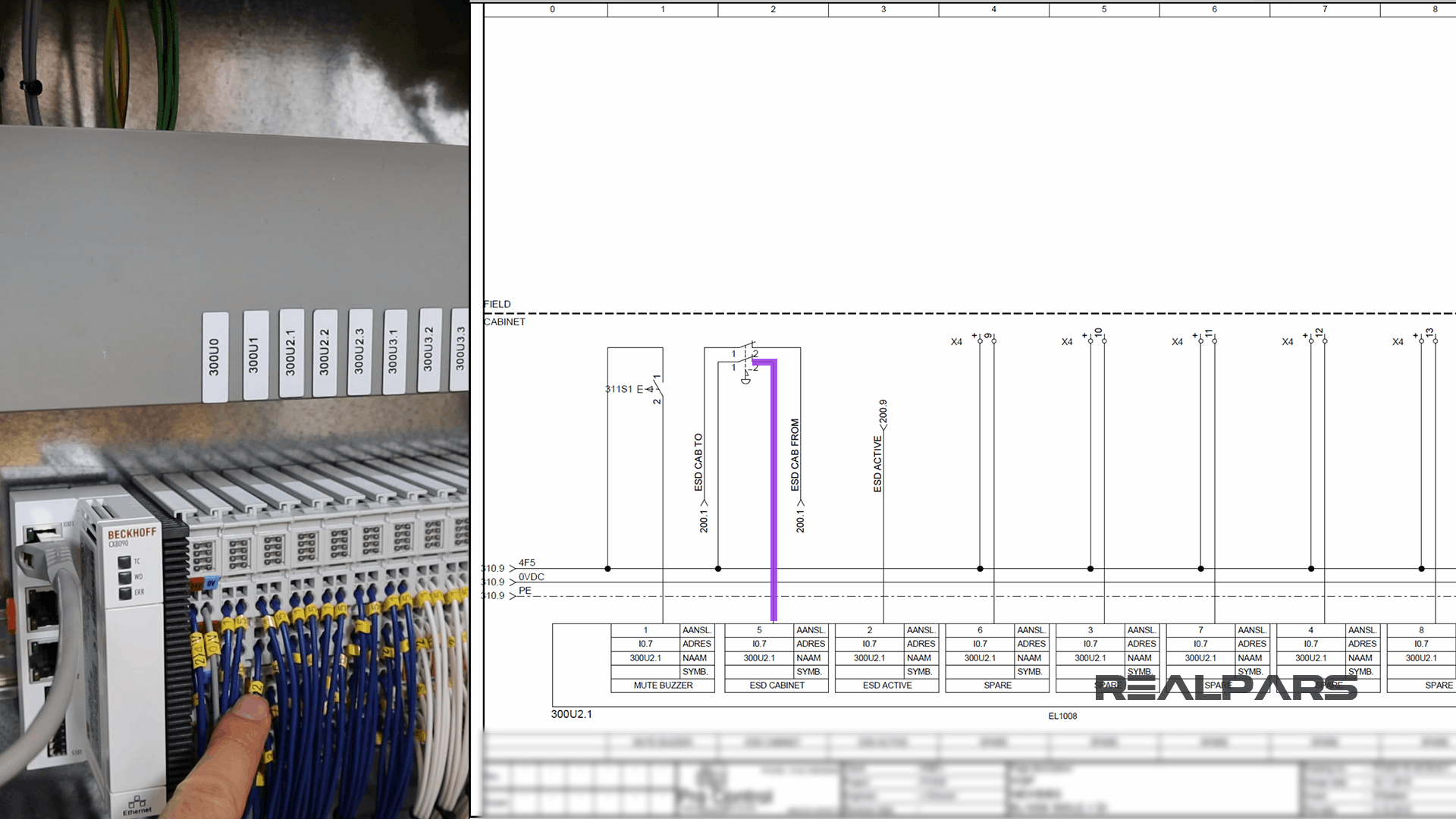
One end of this diagram is connected to the push button and the other end is connected to the PLC input. So this is how easy it is to read the wiring diagram for a control panel.
It goes exactly the same for the other switches that we have here as well.
Summary
So to sum it all up, here is what we learned in this article:
– All the wiring that you see in the panel is done based on the wiring diagram. This is what we draw using AutoCAD Electrical.
– Each page of the wiring diagram shows the exact wiring for different sections of the control panel.
– Each of the wires in the wiring diagram has a tag number. These tags can be found in the panel as well.
– Using the page numbers and the sections, in the wiring diagram, you can easily follow the wires and see where each wire is coming from.
That’s it for this article!
There was a lot of back and forth in that article, hopefully, you didn’t get lost!
If you didn’t, you’re well on your way to becoming an AutoCAD designer, or panel wireman, or maybe you want to work out in the field?! Well, you’re on track for that too.
This article was brought to you by RealPars in partnership with Pro-control in the Netherlands.
They are experts at control system design and industrial automation. They have a team of world-class automation engineers and have been designing and implementing industrial control systems in different industries for many years.
If you want to get in contact with them, you can check out their website at pro-control.nl.
Got a friend, client, or colleague who could use some of this information? Please share this article.