

In this article, you’re going to learn how to use Omron Sysmac Studio 3D simulation function for your robatic applications.
The 3D function is easily added to Sysmac Studio by way of a license from OMRON. We’ll give you more details on that later.
Simulation of a simple sequence
We’re going to start by operating a simulation of a simple sequence already developed and programmed. We begin the sequence by initiating start in the ladder logic.
In Sysmac Studio, the ladder logic control program and the 3D visualization are both dynamically represented on the screen.
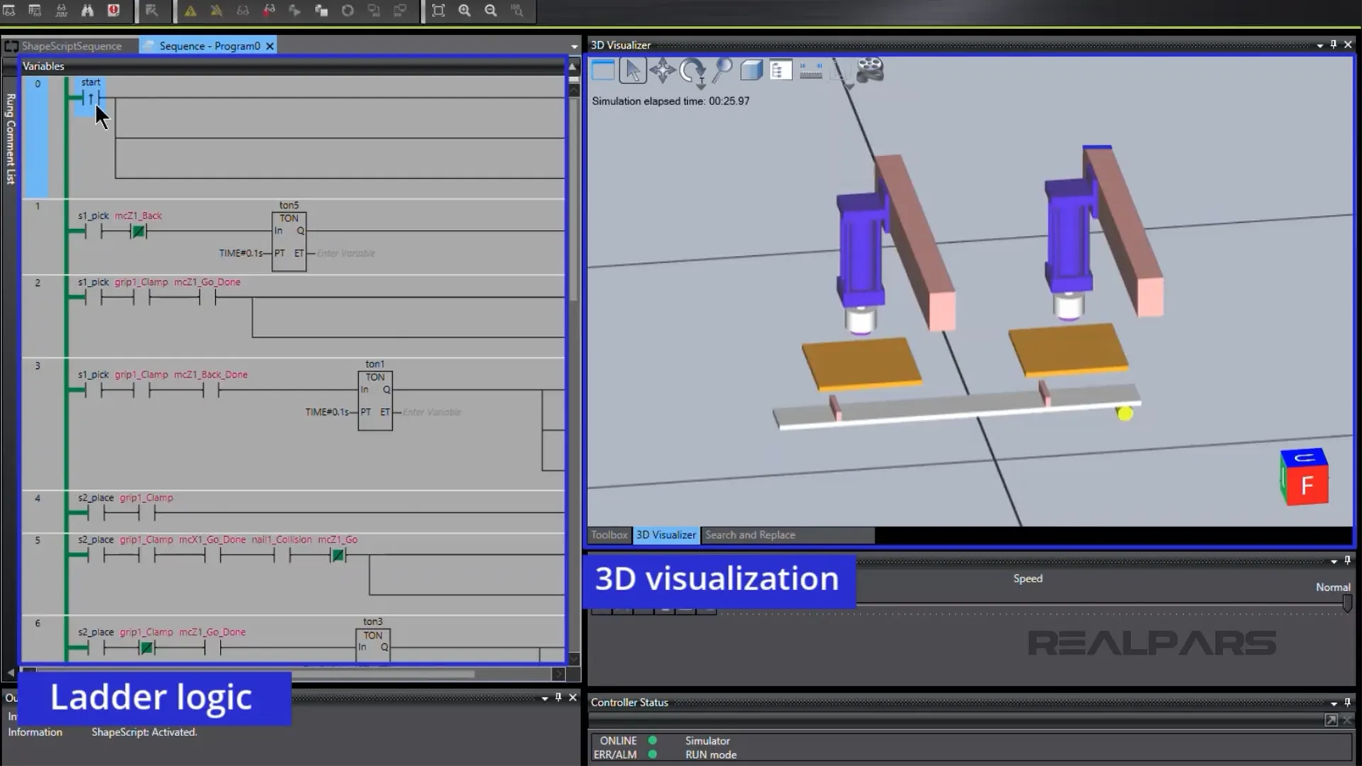
To begin the sequence, we operate the start instruction on Rung 0. The conveyor starts, moves a tray into position, and stops. A part located on a table is retrieved by an air cylinder with a gripper.
The air cylinder with the part moves along a gantry and places the part on the tray once in position.
The conveyor restarts, and moves the tray into a second position, then stops.
As the 3D simulation progresses, you can observe the dynamic changes occurring in the ladder logic as it executes.
A second air cylinder with a gripper retrieves the part, moves to a new location on a gantry, and places the part on a second table.
The conveyor starts again and moves the tray away.
That’s a very quick look at a 3D simulation of a simple sequence.
So, how easy is it to create a 3D simulation?
Creating Sysmac Studio 3D simulation
1. inserting the Application Manager
First, we insert the wizard-based Application Manager.
The Application Manager is unique to the industry as it enables Sysmac Studio to offer a completely software-based 3D Simulation solution without the need for any hardware, at the initial development phase, to test the programming or to create sequences for the machine.
The Application Manager is a virtual device that is added to the project to have access to the 3D Visualizer window and environment where you can add the 3D Shapes and animation scripts.
The bottom line is that a physical device, like a robot, is not needed for a 3D simulation.
After inserting The Application Manager, click on Configurations and Setup and open 3D Visualization.
2. Adding individual components
From the 3D visualization, there are many options to add components.
You can add individual components like a box or a cylinder.
You can add or import CAD files… We will import CAD files later on.
Or, You can add from a CAD library, or import CAD Folder.
Let’s add a box, and view it in the 3D visualizer. From the Configuration and Setup, right-click on 3D visualization, then select Add > Box.
Next, go to the View menu and select 3D visualization.
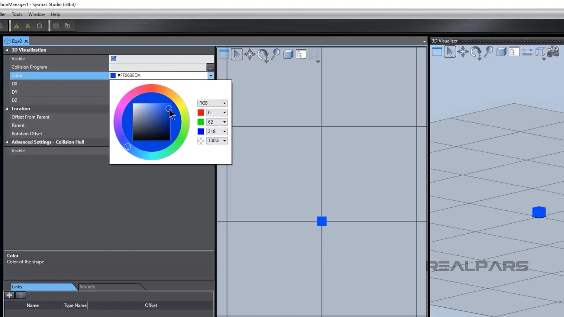
We can change the color and size of the box, by clicking on the created box in the 3D visualizer. To change the color, click on the color dropdown menu and choose the color from the color palette.
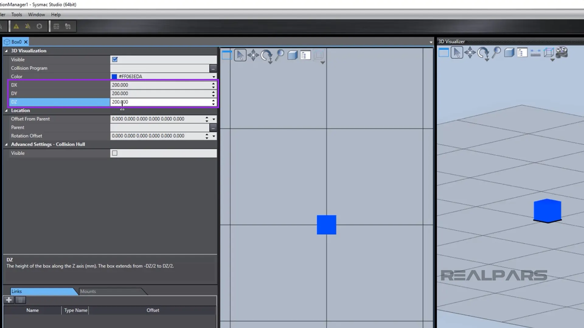
To change the box’s size, modify the left-hand side parameters.
Let’s add a cylinder. From the Configuration and Setup, right-click on 3D visualization, select Add, and select cylinder. As with the box, we can change the cylinder’s color and size.
And, we can change its position relative to its parent, the Box, by modifying the values below the Location, such as Offset From Parent.
We can change the perspective of the 3D Visualizer by clicking on the 3D visualizer, and holding and moving the mouse button while the proper toolbox is selected.
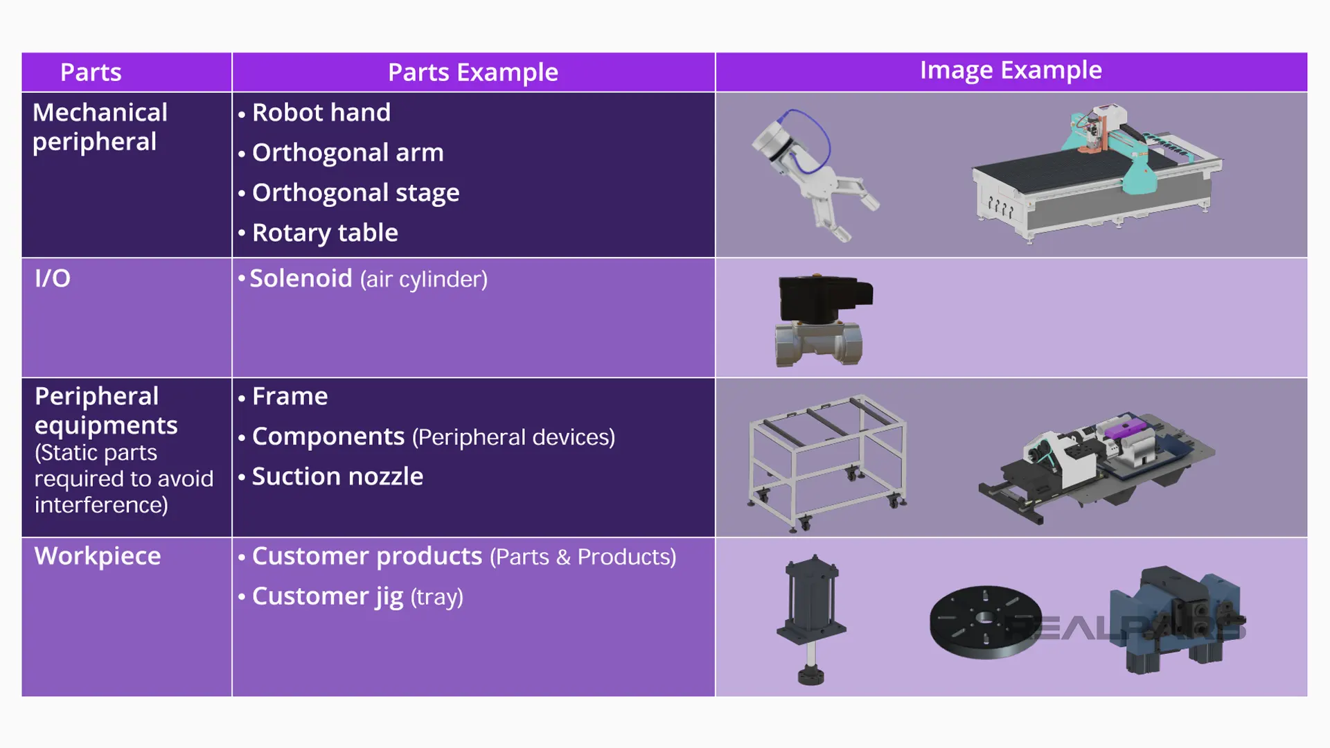
3. Adding mechanical components from a CAD folder
Let’s look at adding mechanical components from a 3rd party CAD folder. From the Configuration and Setup, right-click on 3D visualization, then select Add this time select Mechanical Components.
We are adding a robot from a CAD folder. Therefore, in the popup window, open the Type dropdown list and choose Orthogonal robot (XYZ) and then click ok.
Our folder contains Autodesk STP files that we can insert into our 3D visualizer.
Sysmac Studio supports other CAD files as well, and we’ll tell you more about that later. Select all of the four STP files and click on open. It takes some time for converting the CAD files.
The CAD files are converted.
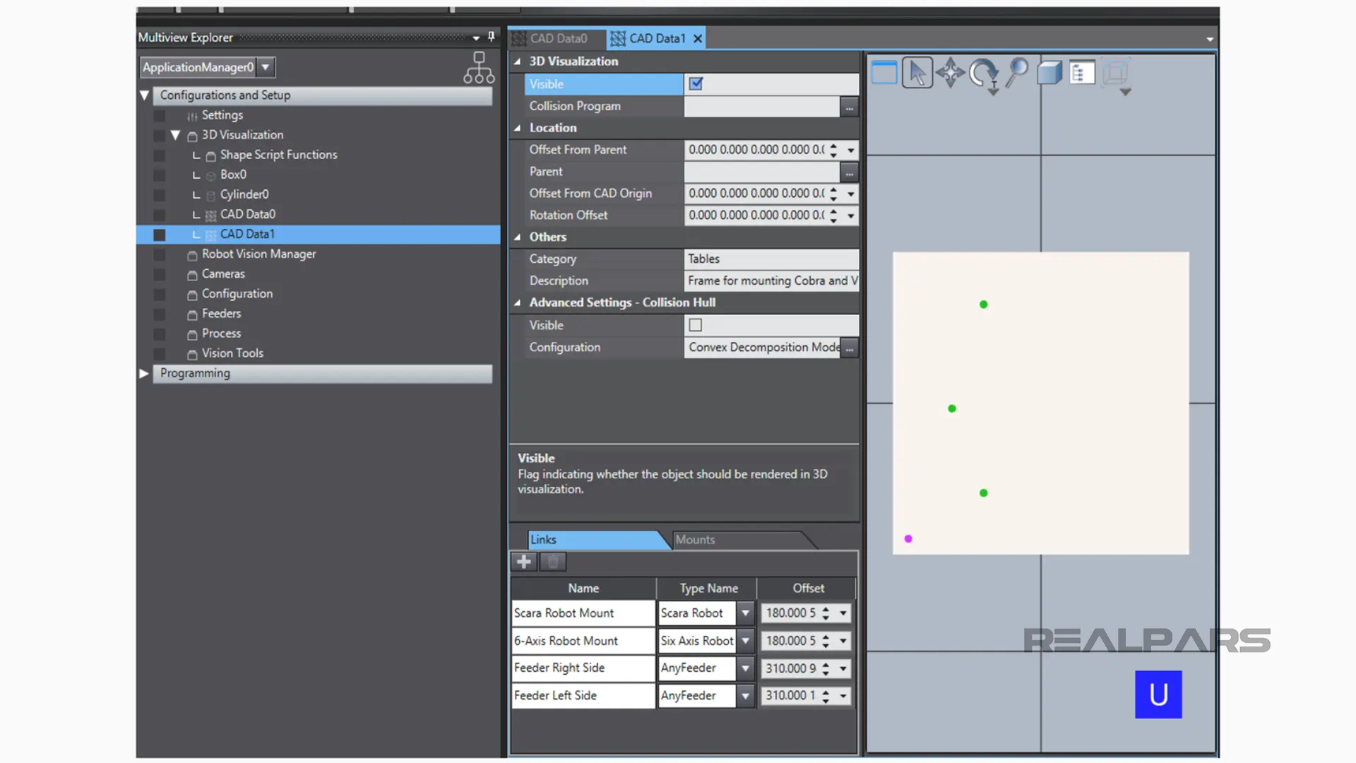
4. Assigning the CAD parts to the moving parts
Once converted, we can assign the CAD part to the moving parts using the Wizard. To do this, simply click on the items below the CAD files list and drag and leave them onto the respective items below the Movable Parts list.
The image can be easily rotated in the 3D Visualizer by clicking on the 3D visualizer, and holding and moving the mouse button.
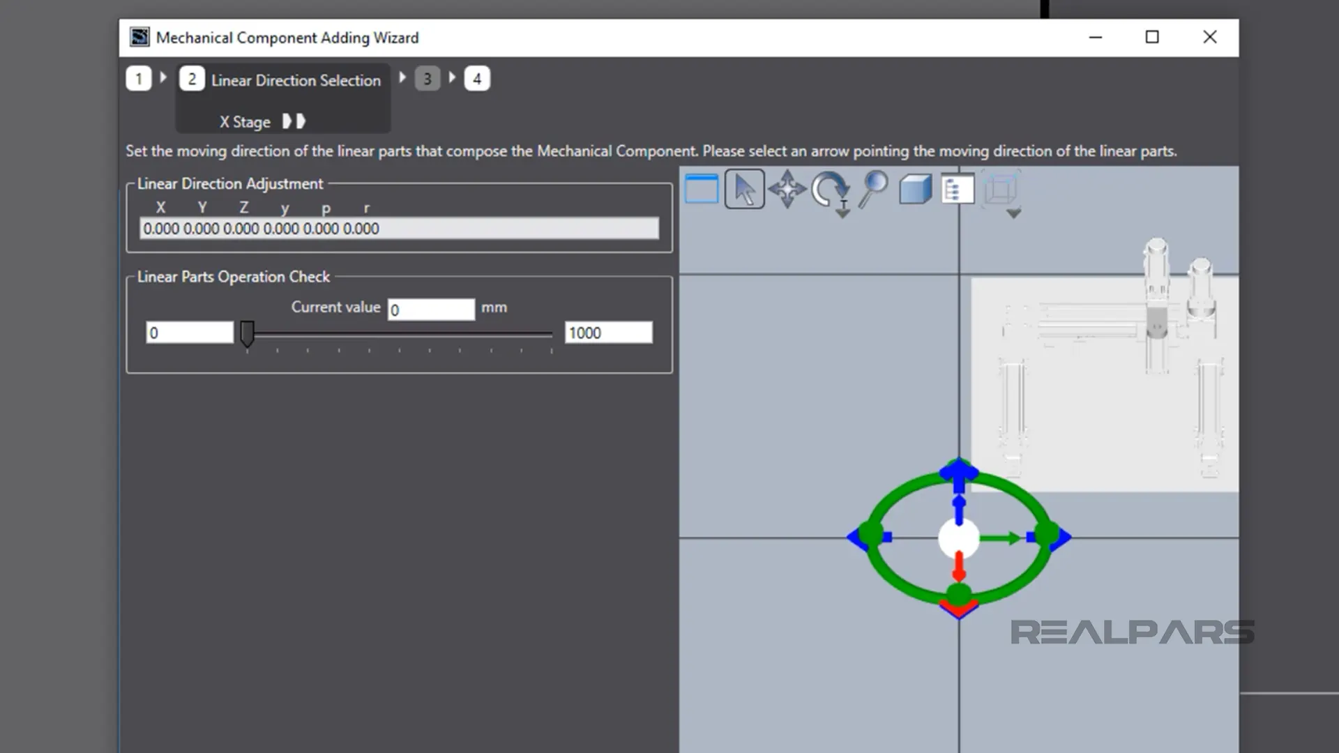
Once the mechanical model has been created, the wizard is used to configure linear part direction and assign motion axes as configured on the Controller (PLC) selected.
If you want to learn about how to create the program for the controller, refer to the RealPars course Omron PLC Programming Basics – Sysmac Studio. Heads up, you need to be a RealPars Pro Member to access this course.
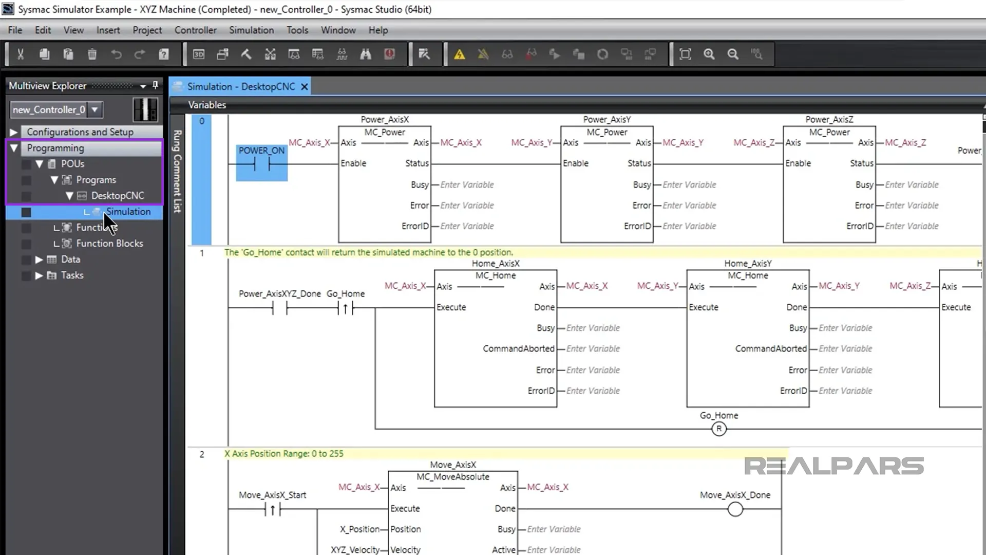
The control ladder logic can be coded anytime. The logic will be added to the Programming section of Multiview Explorer on the left side menu. Extend Programming, POUs, and Programs to see the code that you added before.
Note that you can download the file of this project.
Running Sysmac Studio 3D simulator
Once the simulator is started, the dynamic ladder logic and 3D model are displayed.
The movement of each linear part can be initiated in the ladder logic. The actual travel distance and velocity can be changed while the simulation is running.
So, we can move each component on its axes by operating the appropriate instructions in the ladder logic.
In the simulation, we can move components on the x-axis, by changing the Move_AxisX_Start boolean variable to TRUE, on the y-axis by changing the Move_AxisY_Start boolean variable to TRUE, and on the z-axis by changing the Move_AxisZ_Start boolean variable to TRUE.
Then we can set the Go_Home boolean variable to TRUE to move the Machine part into its home position.
The user-friendly wizard-style setting allows setup simulations using 3D CAD with significantly simpler operations than standard CAD software.
Using the wizard, mechanical component motion axes and I/O signals can be assigned.
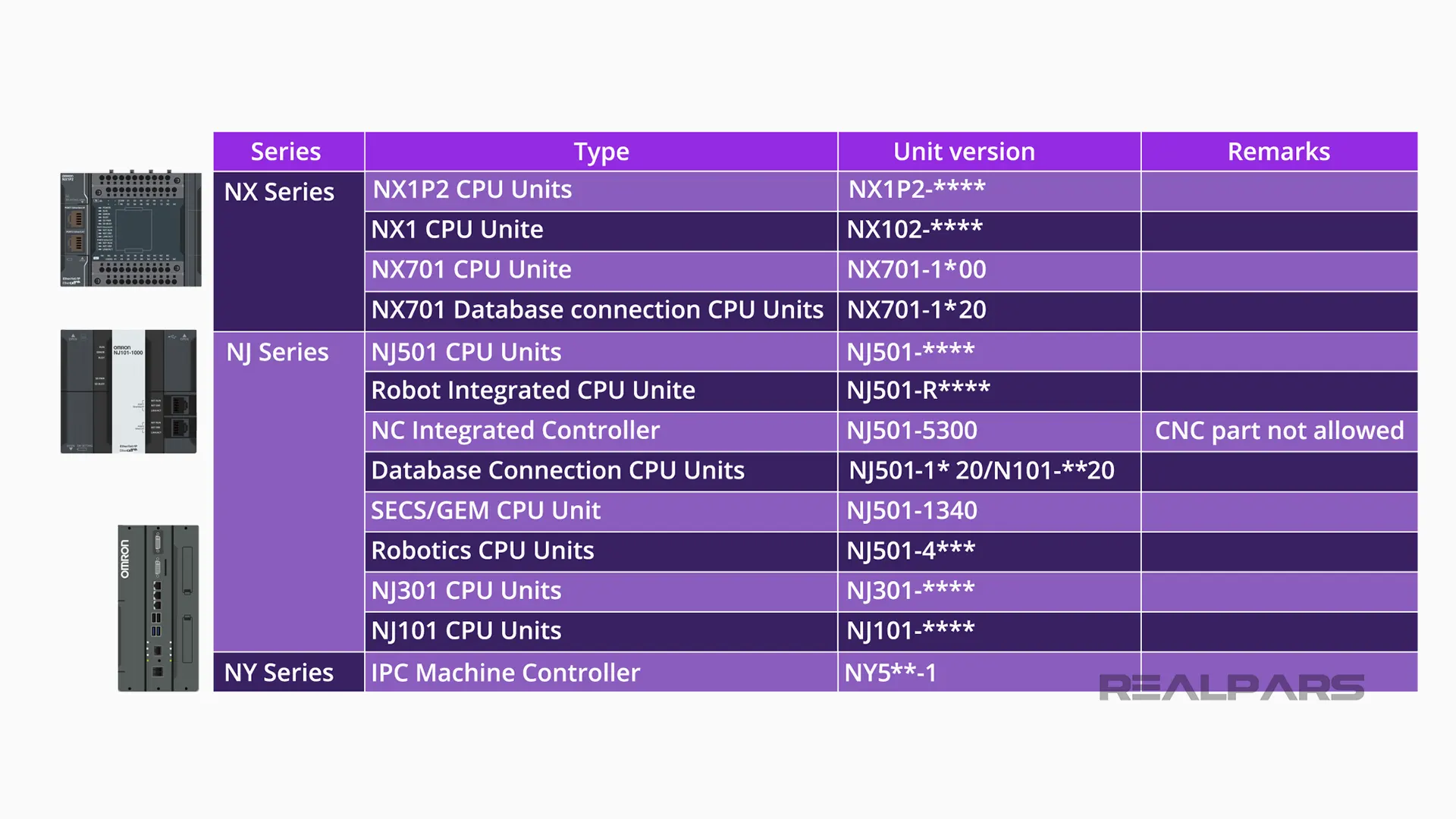
Omron Controllers supported by 3D Simulation
Sysmac Studio 3D Simulation supports the NX, NJ, and NY series of OMRON Controllers with some limitations on the individual controller within a series.
The 3D Simulation function is easily installed on Sysmac Studio once a license has been purchased. There’s also an option to purchase more licenses and/or a site license.
For purchasing the Sysmac Studio 3D Simulation license go to the Omron website. A 30-day Trial version of Sysmac Studio 3D is available from Omron. Please contact your local Sales representative for details.
OMRON provides a detailed user manual for the 3D Simulation function.
Ok… That’s a whirlwind tour of Sysmac studio on how the 3D simulator operates and how easy it is to create and program a 3D model.
Omron’s Robot Integrated Controller
Before we close out, we just wanted you to see the operation of Omron’s Robot Integrated Controller programmed in ladder logic. Using this controller, robots can be controlled with the IEC program making it easy for engineers to control them.
Sysmac Studio supports 8 languages including English, Spanish, French, Italian, German, Korean, Chinese, and Japanese.
For more details on Sysmac Studio, contact your OMRON Regional Office. You can obtain your Regional Office contact details from the OMRON Industrial Automation global site at www.ia.omron.com.