
In this article, we’re going to explain how to read analog input control loop diagrams.
Industrial control loops
Every industrial control feedback system has 2 loops: an input control loop and an output control loop.
Analog input loop
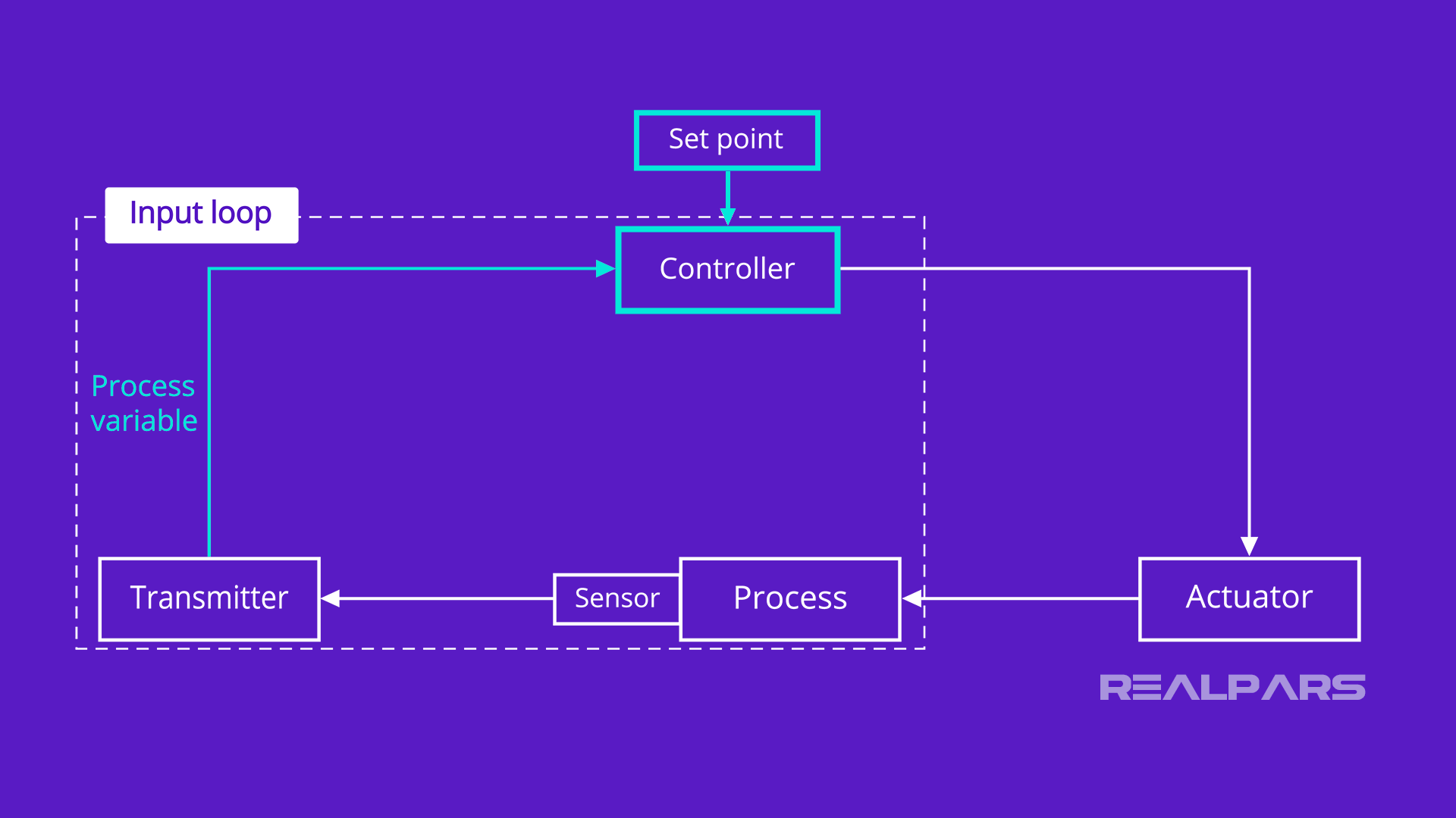
The analog input loop consists of 2 major devices: (1) the transmitter and (2) the controller.
As you can see, the controller is part of both the input and the output loops. In industry today, the controller is part of a PLC or a DCS.
1) The transmitter is the instrument that converts the signal from the sensor to the Process Variable or PV signal which represents the measured variable.
2) The controller is the device that compares the Process Variable or PV and the desired value of the process referred to as the Set point.
Analog output loop
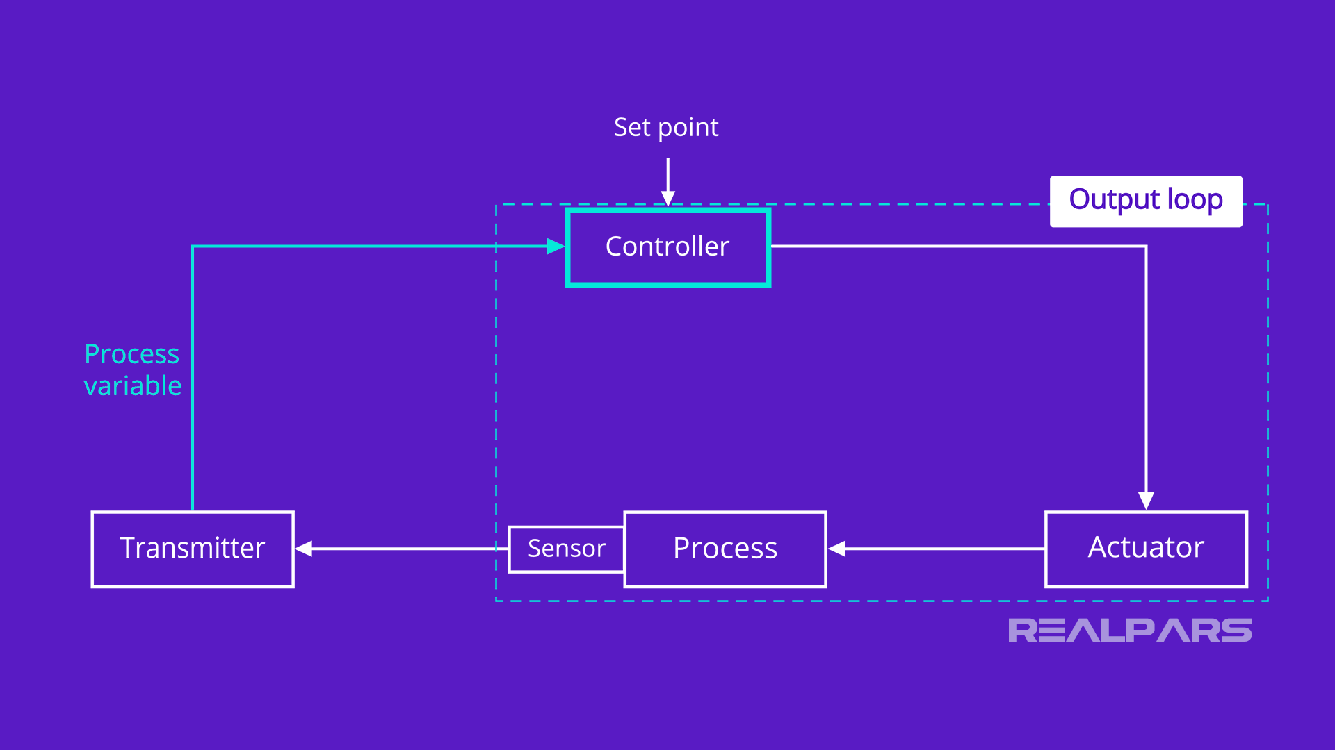
The analog output loop consists of 2 major devices: (1) the controller and (2) the final actuator.
1) When the controller completes the comparison between the Process Variable and the Setpoint, it produces an output signal.
2) The final actuator is the device such as a control valve that exerts a direct influence on the manipulated variable as directed by the signal it receives from the controller.
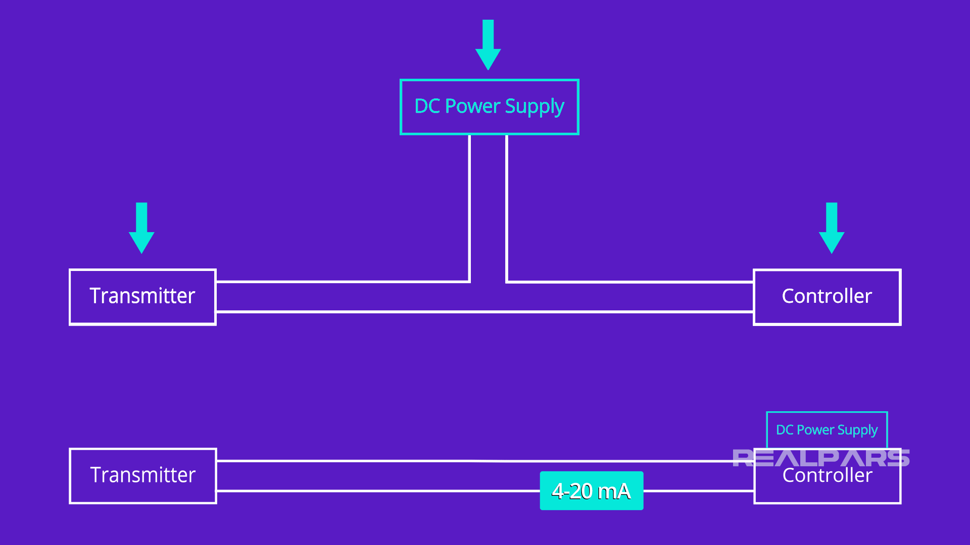
Analog input control loops configuration
Alright, now that we’ve discussed the 2 control loops of an industrial feedback control system, let’s look closer at an analog input control loop.
Most analog input control loops are connected in a 2-wire configuration which requires a DC Power Supply.
In some cases, the power supply is external, and in other cases, the power supply is part of the PLC or DCS. The transmitter signal is usually 4 to 20 mA.
Although companies may have different methods of creating Analog I/O Loop drawings, the transmitter, the controller, and the power supply are common to all.
Analog Input Loop drawings
Let’s look at some typical analog Input Loop drawings and pick out the transmitter, controller, and power supply and see how they are connected to each other.
Analog Input Loop drawings (example 1)
Here’s our first example. The Power Supply located in a LOCAL CONTROL PANEL is used to power many loops.
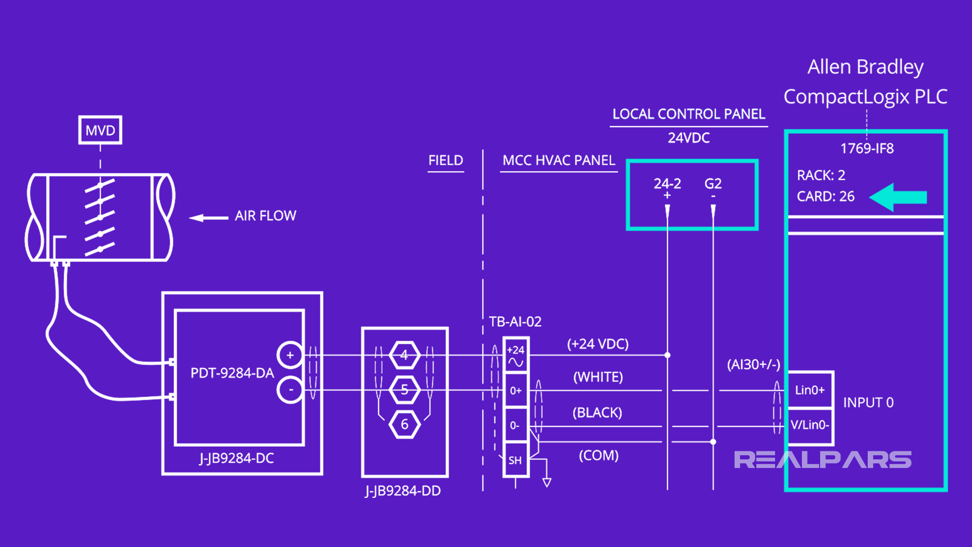
The Transmitter is connected in a 2-wire configuration with the Power Supply and the Controller through terminal block TB-AI-02.
The Controller is one of the channels, (Input 0), of an Allen Bradley CompactLogix PLC Analog Input module. This module is located in Rack 2, Slot 26.
If you are curious to know more about the Analog Input module, do a google search for 1769-IF8.
Analog Input Loop drawings (example 2)
Okay, let’s look at another example and see if we can find the transmitter, power supply, and controller.
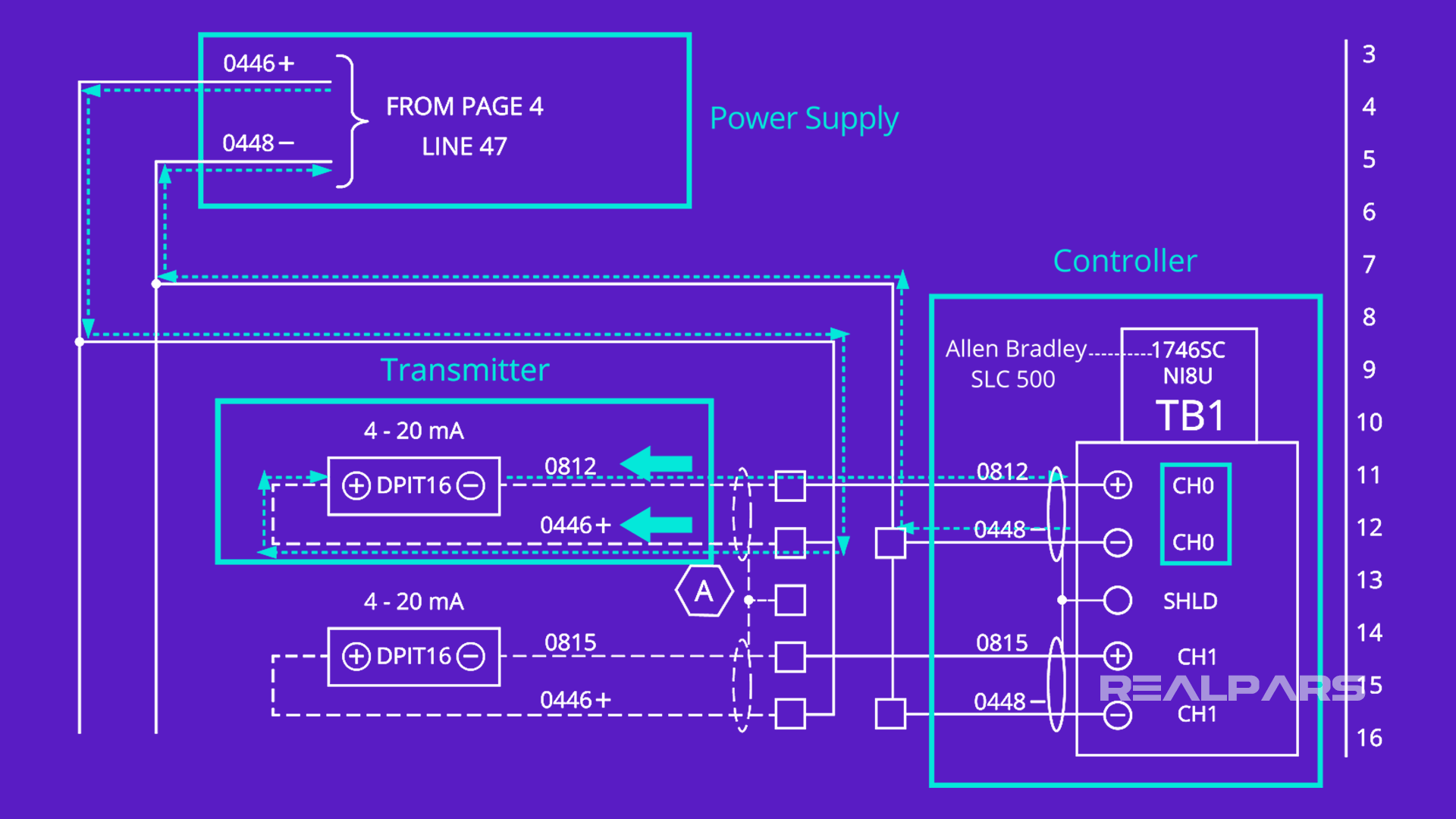
The Power Supply is found on the drawing on Page 4, Line 47 of the entire multi-page document. The power supply is used to power many loops as well.
The Transmitter is connected in a 2-wire configuration with the Power Supply and the Controller through wires labeled as 0812 and 0446.
The Controller is one of the channels, (Channel 0), of an Allen Bradley SLC 500 PLC Analog Input module.
Unfortunately, this drawing doesn’t give us much of a clue as to where the module is physically located.
If you want more details about the Analog Input module, do a google search for 1746SC-NI8U.
Analog Input Loop drawings (example 3)
Let’s look at an example of an Analog Input Control Loop with a DCS Controller.
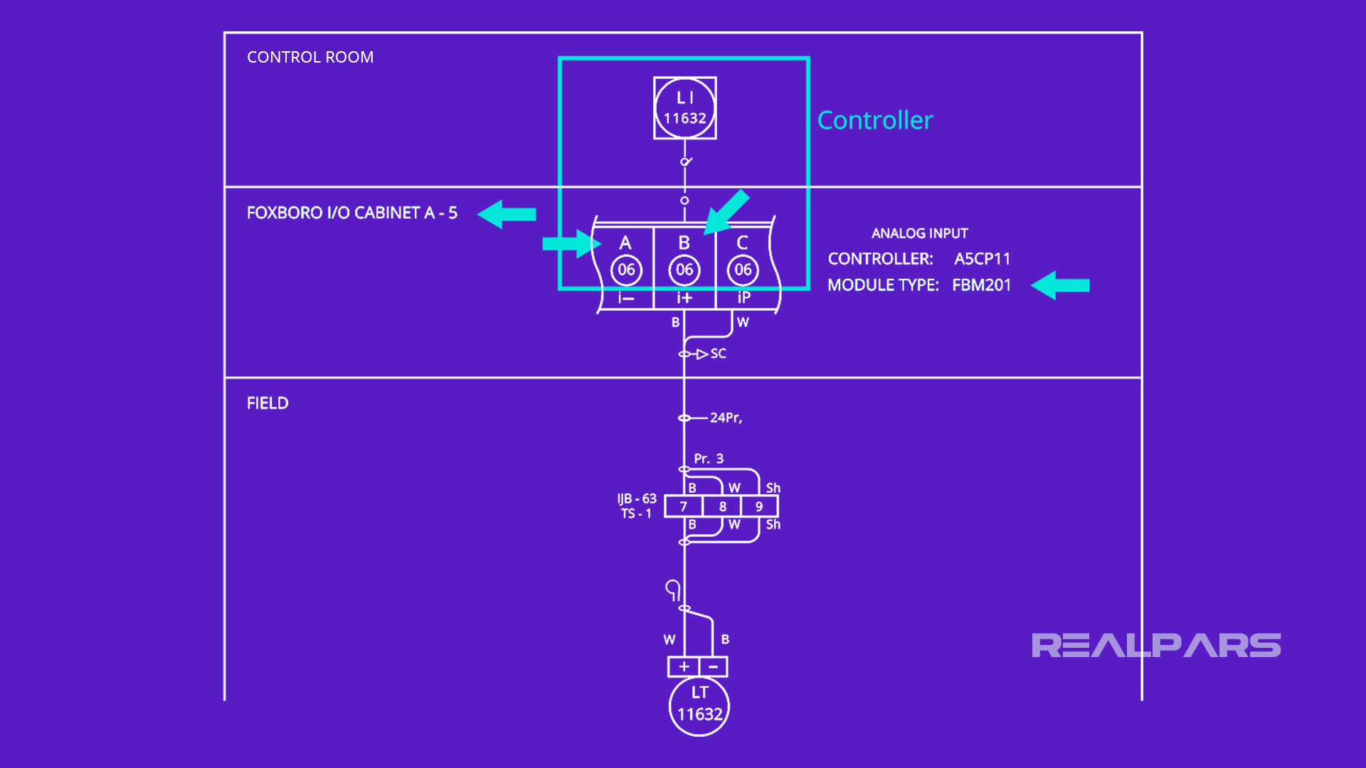
The Controller is one of the channels of a Foxboro DCS Input module FBM201. This module is located in the Foxboro I/O Cabinet A-5.
The datasheet for the FBM201 Analog I/O module will tell you that the 2-wire input and output connections are A and B.
The P&ID symbols tell us that the Control Room HMI will have a graphic for a Level Indicator LI11632.
The Power Supply is not obvious in this drawing. The datasheet for the FBM201 Analog I/O module will tell you that the Loop Power originates from the DCS and is connected to Terminal C.
Although it’s not shown, the Power Supply return is connected to A on FBM201.
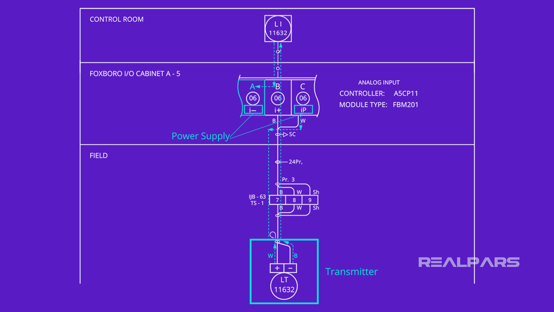
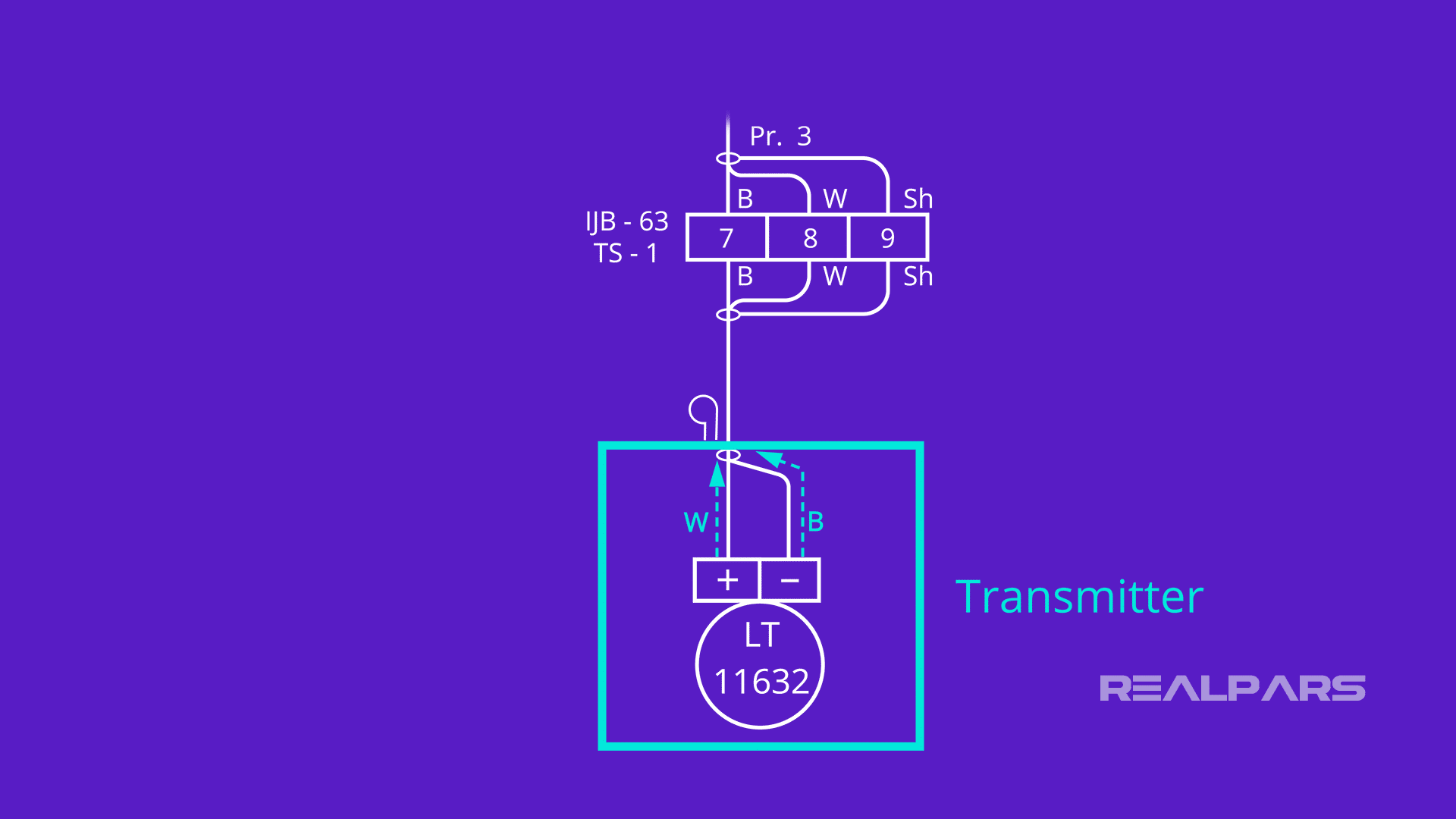
The Transmitter is connected in a 2-wire configuration with the Power Supply and the Controller through wires labeled W and B.
Summary
Let’s review what we’ve discussed.
– Every industrial control feedback system has an input control loop and an output control loop.
– The analog input loop consists of the transmitter and the controller.
– The analog output loop consists of the controller and the final actuator.
– Most analog input control loops are connected in a 2-wire configuration.
– Regardless of the industry or the company, the transmitter, controller, and the power supply are common to all Analog I/O Loop drawings.
You might want to review 2 of our other articles:
1) PLC Analog Inputs and Signals
2) What are 2-wire and 4-wire Transmitter Output loops?
If you would like to get additional training on a similar subject please let us know in the comment section.
Check back with us soon for more automation control topics.
Got a friend, client, or colleague who could use some of this information? Please share this article.
The RealPars Team