What are the Different Parts of a PLC?

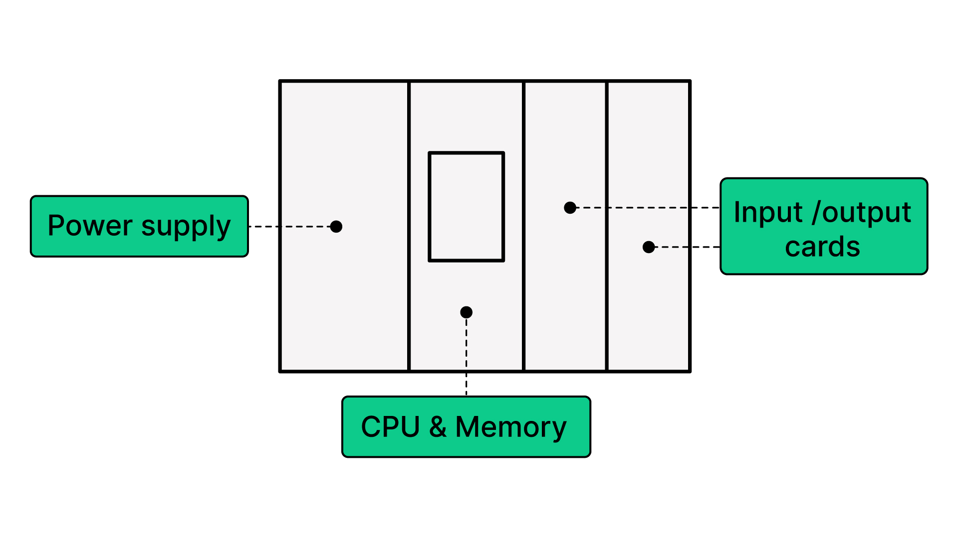
PLC parts include the power supply, central processing unit, memory, isolation bus, network card, input and output cards, and programming interfaces.
Power supply
The power supply converts power that will be used by the central processing unit (CPU), memory, and the rest of the components. It normally is fused. It may be a specific line voltage and varies by country. In the United States, it's typically 120 VAC and 60 Hz.
Many companies have gone toward supplying the PLC with 24 volts due to safety. Thus, the source power coming in could be 220 VAC at 50 Hz and then converted to 24 Volts AC.
The best approach is to check the power supply requirements to determine the necessary voltage and maximum current. This ensures that the PLC is connected to a suitable circuit capable of providing adequate full-load amps.
In this article, we are just discussing the parts of the PLC. Hardware design may be covered in a separate lesson.
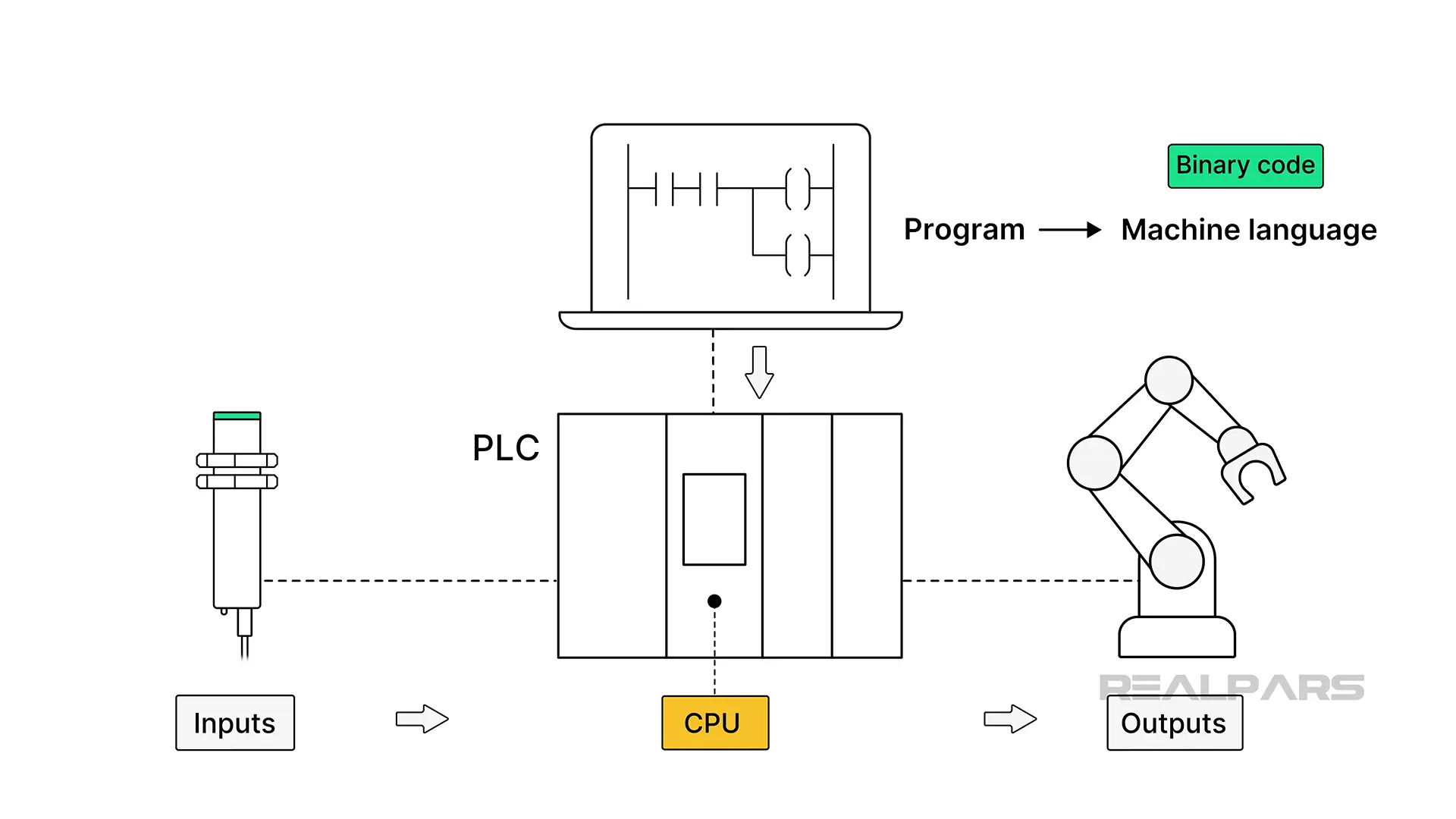
Central Processing Unit (CPU)
A PLC has a controller that is a CPU. The CPU will be able to take a program and convert the program into machine language.
There will also be an interface such as an external PC for programming so that an executable program may be downloaded to the controller.
The machine language consists of sequences of 1’s and 0’s or binary code, telling the computer how to manipulate the inputs and what to do with the outputs.
A program is downloaded into the CPU, and signals based on decisions are sent out to the field. The program's purpose is to monitor the inputs and make decisions based on the application the PLC is being used for.
Memory
Memory may be part of the CPU or located on a separate card. Wherever the memory is located, it stores data. The program is stored in memory as a run-time executable file. Each input and output will have a register or a location where the CPU keeps its values.
Output registers are used to correlate to physical output locations that will receive a signal once the program decides what to do with the input feedback.
For instance, a table that corresponds the registers to the inputs and outputs could be used to set up the program. Even some PLC applications will have this kind of register table for memory allocation inside the programming environment.
.webp)
Why is it important to understand the memory allocation in a PLC? Memory allocation affects scan time.
Understanding how your PLC memory is configured will influence how tag assignments are made and help you understand register assignments for inputs and outputs.
If you want to learn more about programming PLCs, take a look at the RealPars PLC Programming courses.
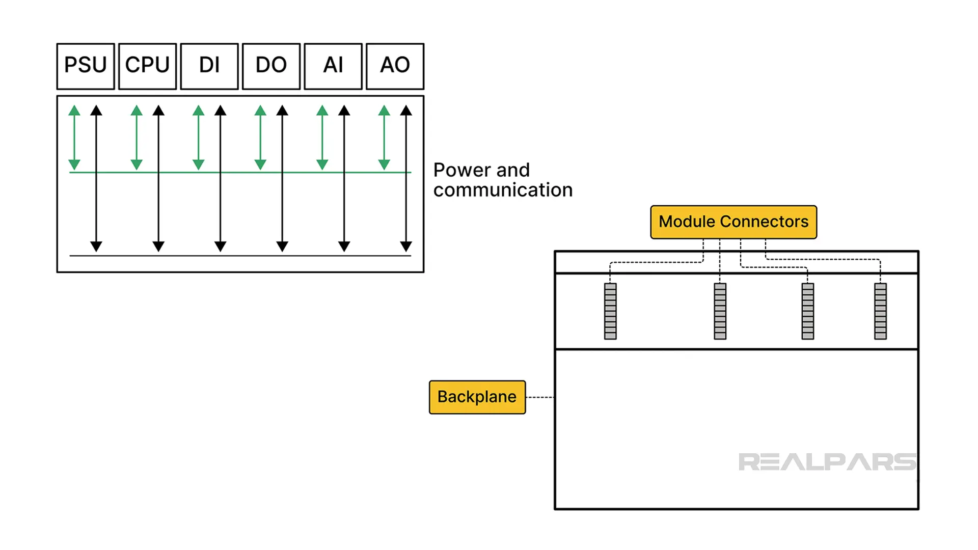
Isolation bus
The power supply provides source power to drive the CPU and the input and output cards, or any kind of power on the PLC rack.
Power and communication can be bussed on the PLC backplane. Think about it as where the “cards” are seated on a bus. The cards on the PLC rack share power. They get the power off the bus.
When sizing a fuse or circuit breaker for the PLC rack, the power consumption across the whole rack should be understood.
Hardware engineers use fusing or circuit breakers to isolate components and protect upstream connections. Also, sometimes, a repeater card is needed in the PLC rack to extend the power bus because different PLC cards consume different amounts of current based on their functionality.
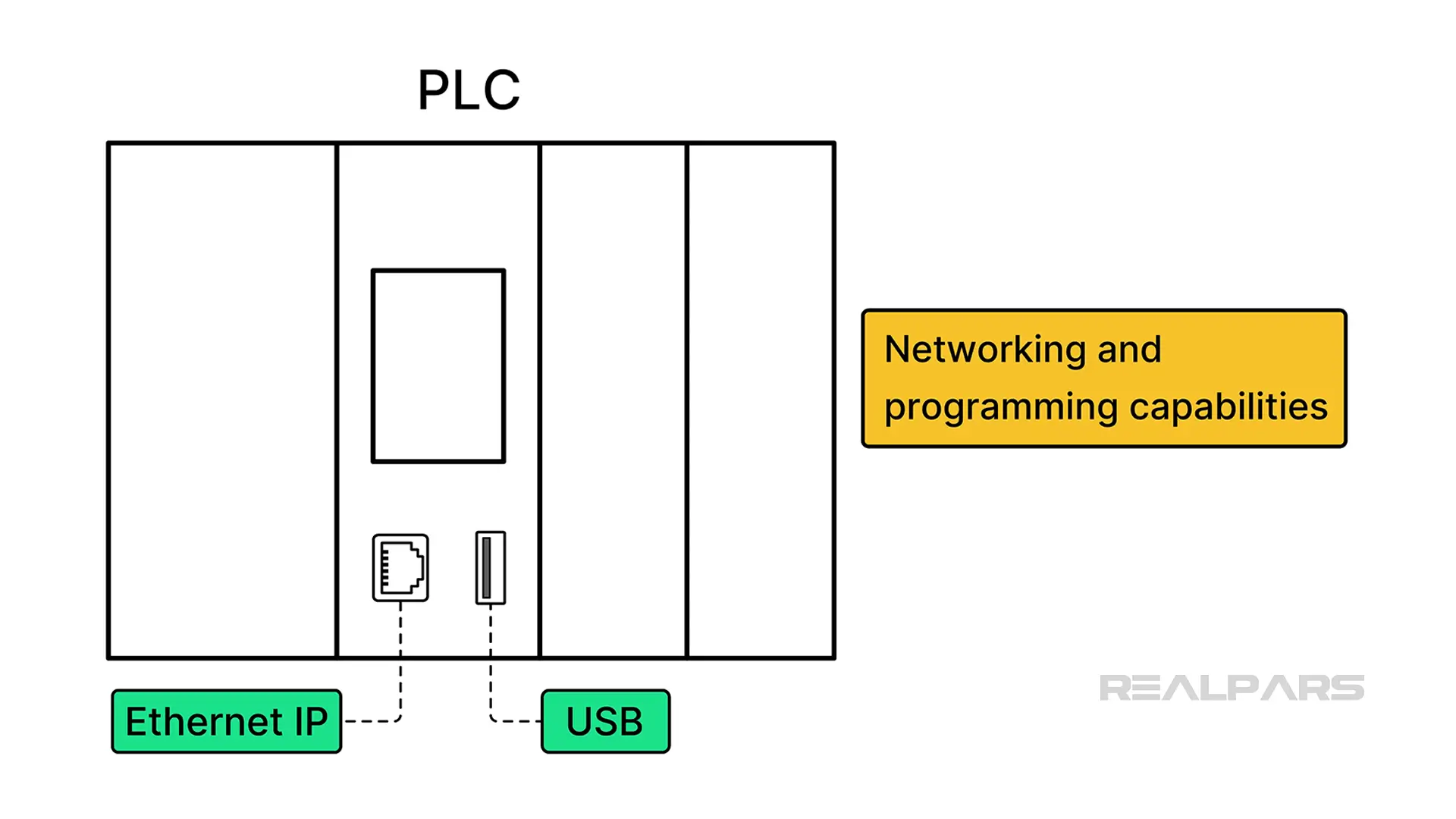
Network card/interface
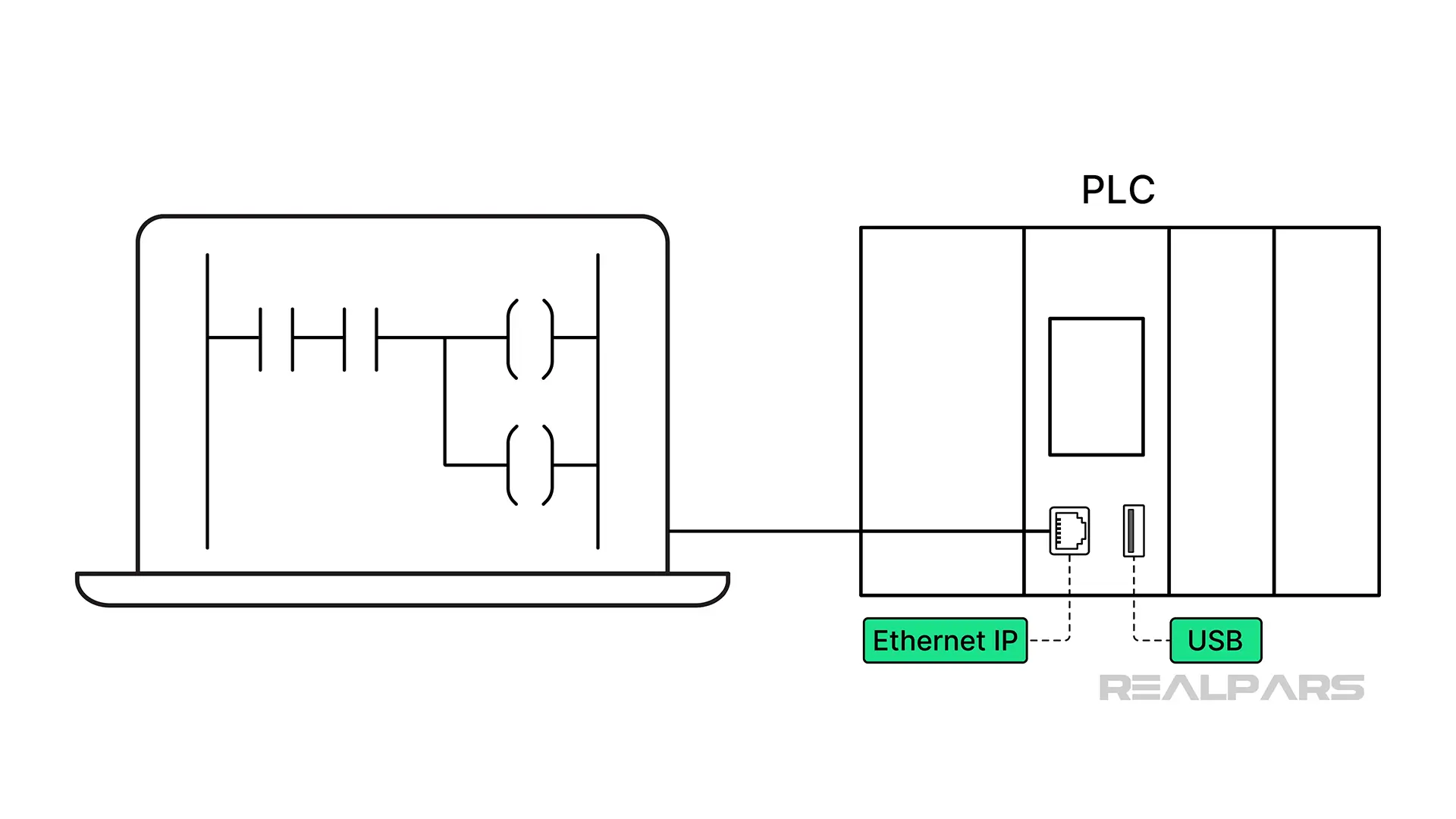
The PLC has to be able to be networked or programmed so there needs to be some physical communication port.
This communication port may be an Ethernet IP port, a USB port built into the CPU, or a separate card type that connects to the bus.
There are other protocol types as well, like Profibus, serial communications, and sometimes wireless radio interfaces. Another type of interface is IO-Link, and this RealPars IO-Link article explains IO-Link in more detail.
Programming interface
PLCs’ have a programming interface where a connection may be made via Ethernet or a USB port. This port is used to connect the software design environment to the PLC.
Inputs and outputs
The PLC chassis has slots that are allocated in the rack for the input and output (IO) cards. Field terminal blocks are wired to the IO cards.
These allow versatility due to being discrete, analog, high-speed counter, or thermocouple inputs. There are many types of cards and card configurations.
Power, space on the rack, and application needs will determine what kind of cards are required for a PLC to execute and meet the application requirements successfully.
Keep in mind that there are many PLCs and many forms of PLCs. Thus, we are only showing examples here in an effort to show what a PLC and the parts of a PLC look like.
Today’s architecture could include remote IO racks which means all of the “cards” are not always in the same rack. These instances have different network and power requirements.
Please refer to the RealPars Remote IO to learn more about Remote IO.
Conclusion
In conclusion, PLCs may have the format of a “brick” type, where the I/O is fixed in place, or a rack type, where the cards are in slots on a rack, or a soft PLC configuration where the PLC is software operating as an application running on a computer operating system.
However, the PLC will still have a power supply, a control processor, memory, a bus, and an inputs and outputs interface.
Today’s automation landscape also tends to put things in the cloud. Thus, the idea of PLC may not take just one form. The beauty of configurable computers like the type that a PLC is, allows for versatility.
If you are interested in learning PLC basics, several courses, such as PLC Fundamentals for Control Systems and PLC Hardware Fundamentals, can help you.
Frequently asked questions
Learn from Industry Experts
With a 7-day trial, then €35/month