PLC Basics | Programmable Logic Controller

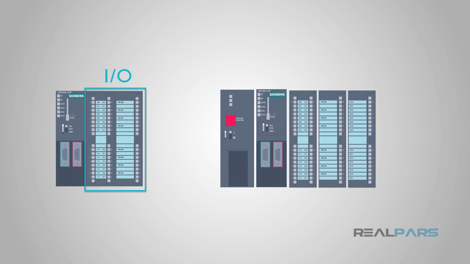
Today we are going to talk about programmable logic controller basics. The programmable logic controller, or PLC, is a special purpose computer. It has no display, no keyboard, no printer, no hard drive, and hides in the control panel out on the factory floor, but it is still a computer. Keep reading to learn the basics of PLC programming.
Initially, the PLC was a replacement for panels of relays, devices that turn on and off. Making a machine run using relays as logic was time-consuming and challenging, and making a change in the logic or the operation of the machine was almost as complicated as starting over.
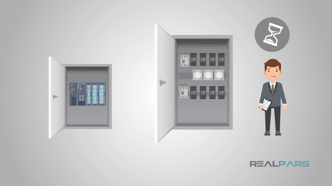
Relays also fail far more frequently than computer components, so that relay logic required more downtime to keep it running than newer PLC-based controls.
On top of all of that, relays use a lot of electricity, make lots of heat and soot, and take up lots of space.
An installed PLC is deceptively simple in appearance. You have a CPU module and input/output devices, referred to as I/O. Sometimes the I/O is part of the CPU, and sometimes it is in other modules.

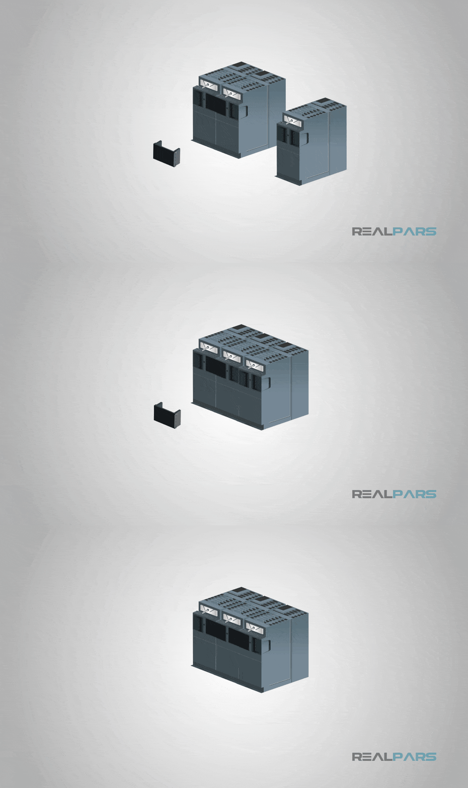
The CPU communicates with the I/O, so in most systems they share a backplane that physically holds them in place and electronically connects them.
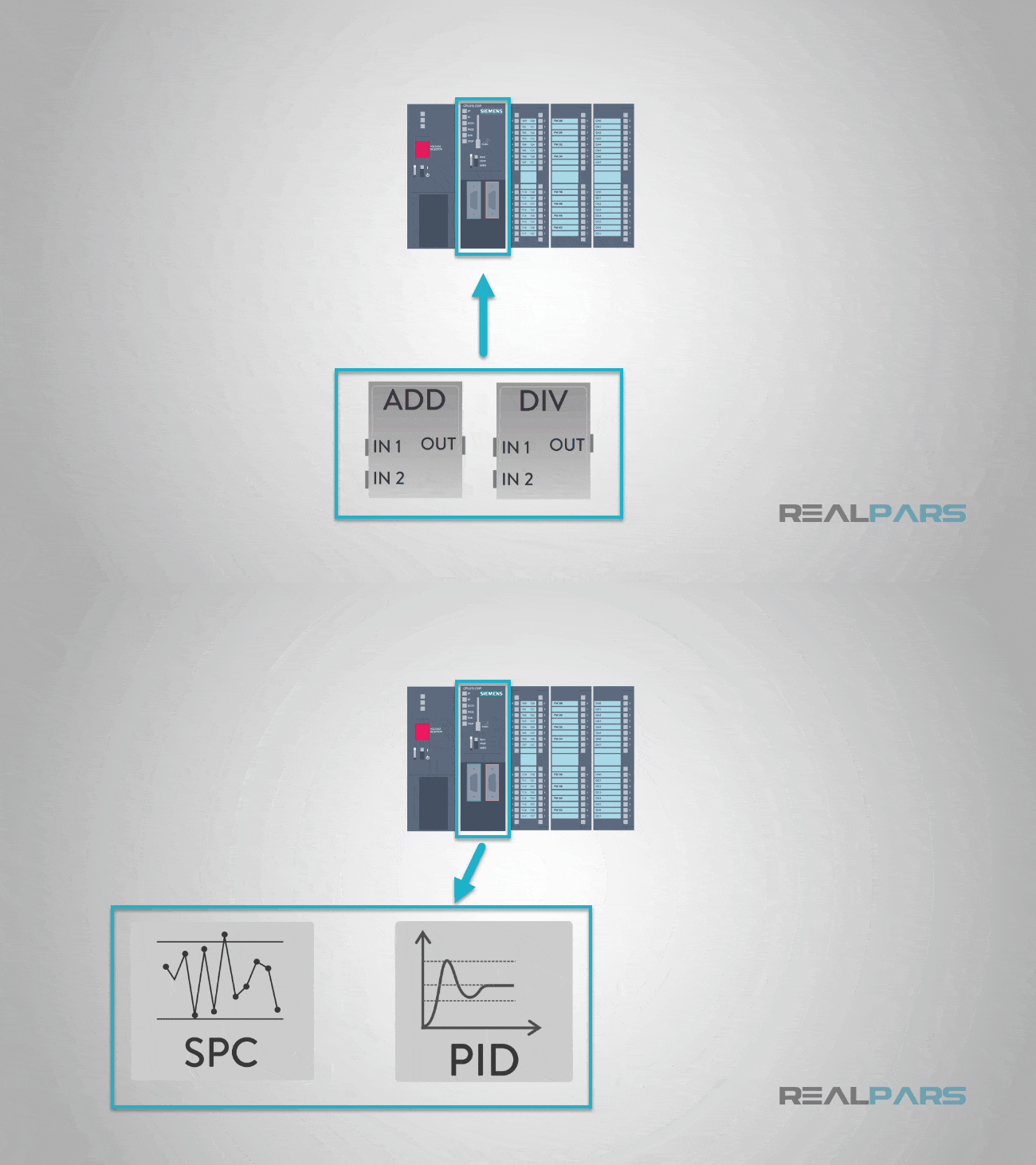
In other equipment, the I/O modules can be miles away from the CPU and connected with data cables, so that the PLC is not limited to a single cabinet or even the same building. Since the PLC is a computer, there is no need to limit it to only digital inputs and outputs. Over the years, the manufacturers added analog and other numerical inputs and outputs.
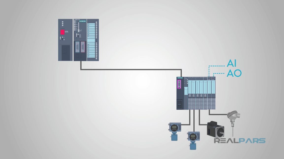
To make these numerical devices useful, they included calculation capability in the programming as well, so that we can now calculate, for instance, statistical process control (SPC) values and put PID controllers directly into the PLC program.
Since this is called a programmable logic controller, we need to program it. Most PLCs are programmed using an application running on a standard desktop or laptop PC.
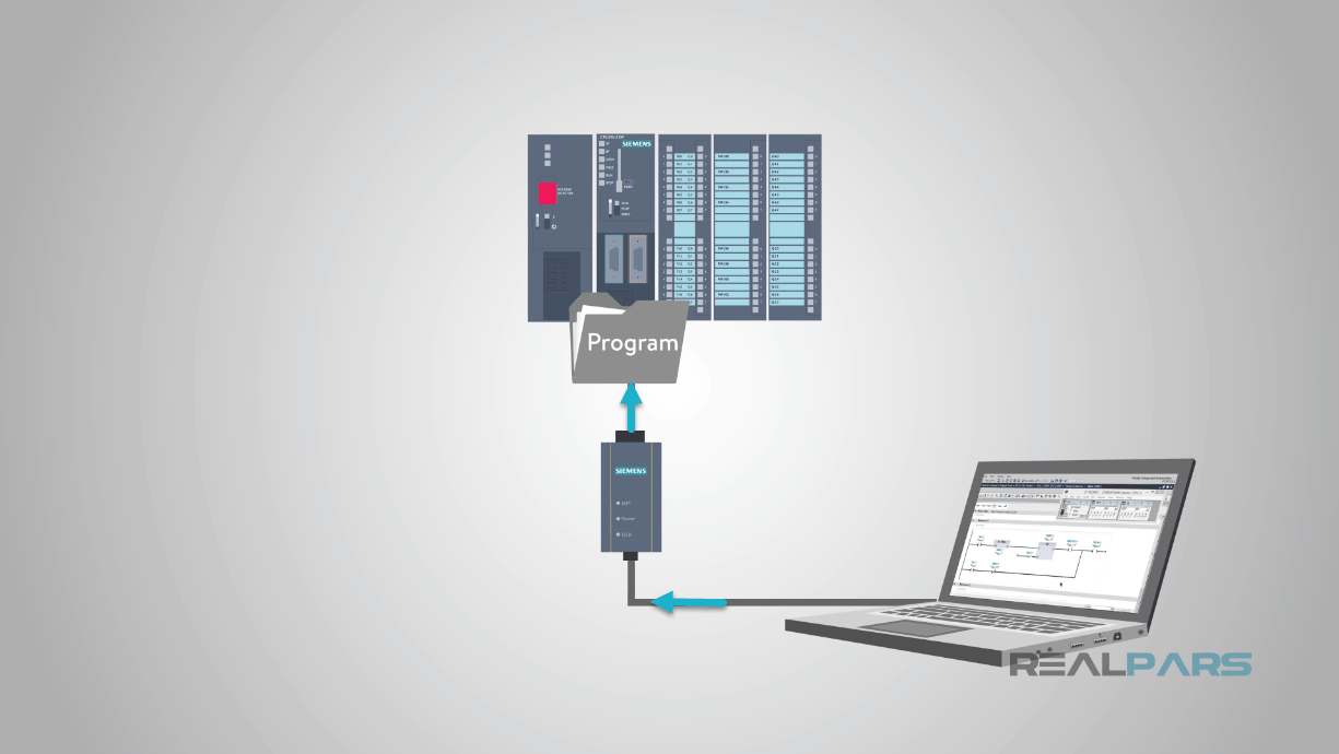
They communicate with the PLC using Ethernet or a proprietary communication bus, depending on the manufacturer. Most manufacturers seem to have settled on Ethernet and/or USB in recent years.
Unfortunately, the PLC manufacturers have failed to agree on how we program the control logic. Although most of the manufacturers claim some form of “Ladder Logic,” the specifics of that language are different for each manufacturer, including different capabilities, different ways of doing the same thing, and even differences in the order in which the CPU processes the various pieces of logic.
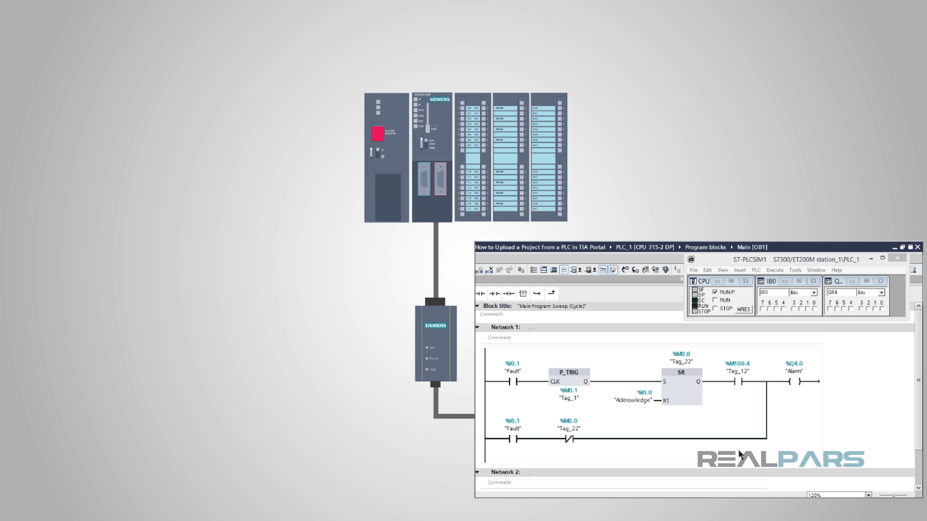
One attempt to bring some order and inter-operability to this chaos is the IEC 61131 standard from the American National Standards Institute (ANSI). The excerpt from the ANSI web page gives a flavor of what is there.
The IEC 61131 standard defines several “programming languages” with different strengths and weaknesses. Local programming standards – your boss or the customer – will usually specify what language you use.
That wraps up this short discussion of the structure of PLCs – I hope you enjoyed this little introduction to the underlying architecture of many industrial control systems. Keep watching as we continue our exploration of the basics of industrial controls.
I hope this video has helped you. Make sure to check back later for more awesome videos!
Thank you so much for watching, sharing and continuing to be a part of our world.
With so much love and excitement,
The RealPars Team
Frequently asked questions
Learn from Industry Experts
With a 7-day trial, then €35/month