What is a Stepper Motor and How it Works?

In this lesson we will discuss what a stepper motor is and how a stepper motor works, so let’s first determine what a stepper motor is and examine some unique features of a step motor.
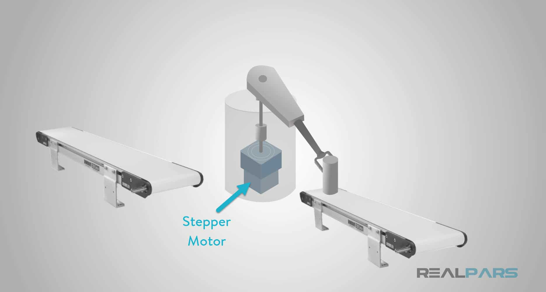
Have you ever thought about how a robotic arm moves with precision or how graphic printers create accurate replications of images, or how consumable products are moved precisely around a plant floor or any other type of motion control positioning system?
With this lesson and others to follow you will learn about motion control using different types of motors available, primarily stepper and servo motors.
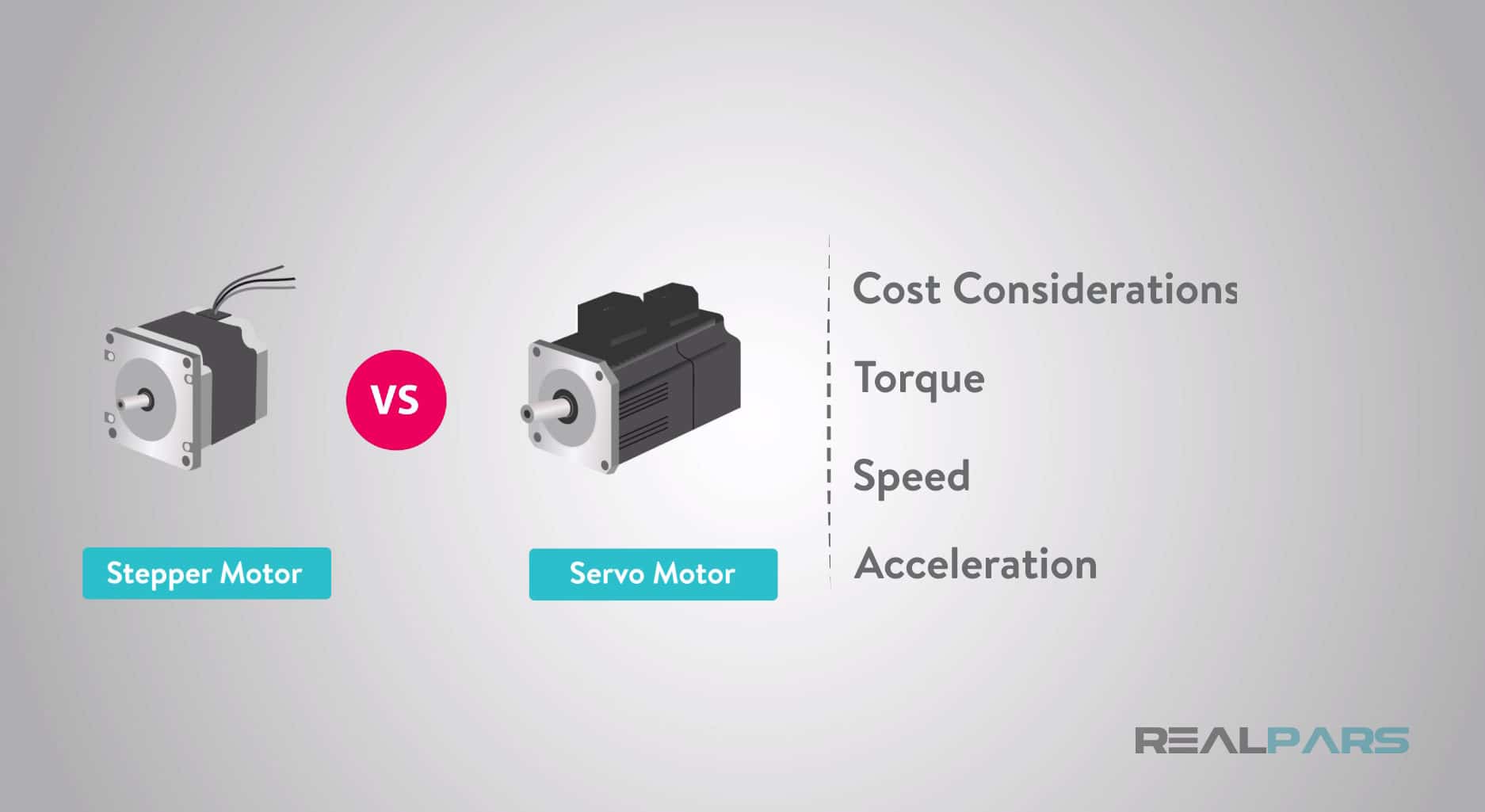
Selecting between a servo motor and a stepper motor can be quite a challenge with the balancing of several design factors in cost considerations, torque, speed, acceleration, and drive circuitry all play an important role in selecting the best motor for your application.
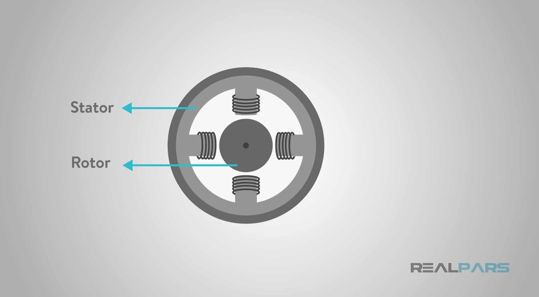
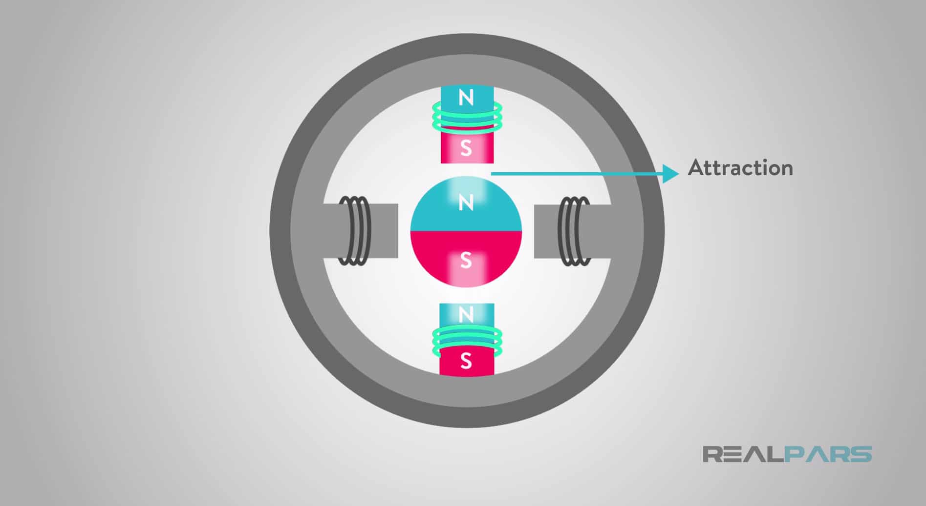
So how does a stepper motor work? Stepper motors have a permanent magnetic rotating shaft called a rotor and stationary electromagnets surrounding the rotor called the stator.
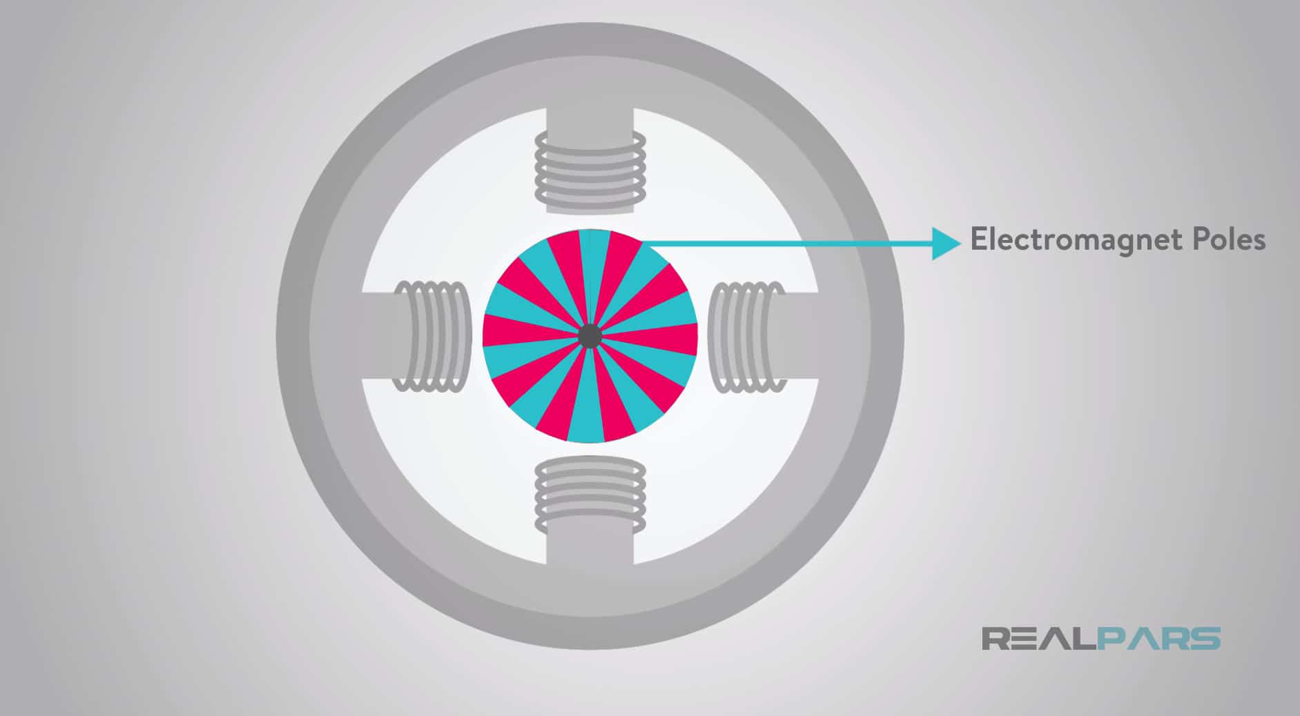
Stepper motors have typically 50 to 100 electromagnet poles (pairs of north and south poles) generated either by a permanent magnet or an electric current.
Each permanent magnet pole offers a natural stopping point for the motor shaft.
The greater number of poles allows for a stepper motor to position itself accurately and precisely between each of the poles.
This is a convenient feature of the stepper motor in that the poles within a stepper motor allow it to be positioned accurately without any positional feedback.
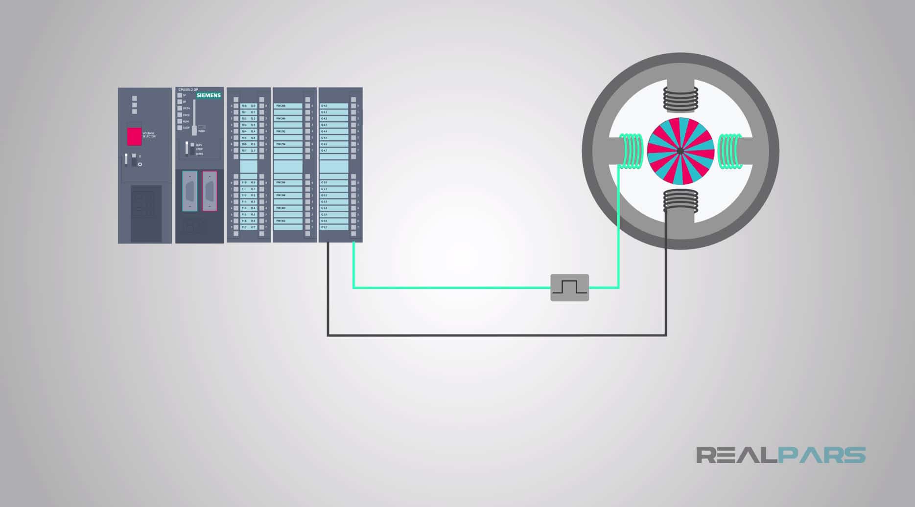
In other words it works in an open-loop control system. The open-loop control allows for a single electrical pulse from a controller to move the motor shaft from one pole to the other and stop aligned with the electromagnetic pole without positional feedback to the controller.
This is one of the benefits of the stepper motor, but additional benefits of a stepper motor will be discussed in a separate article.
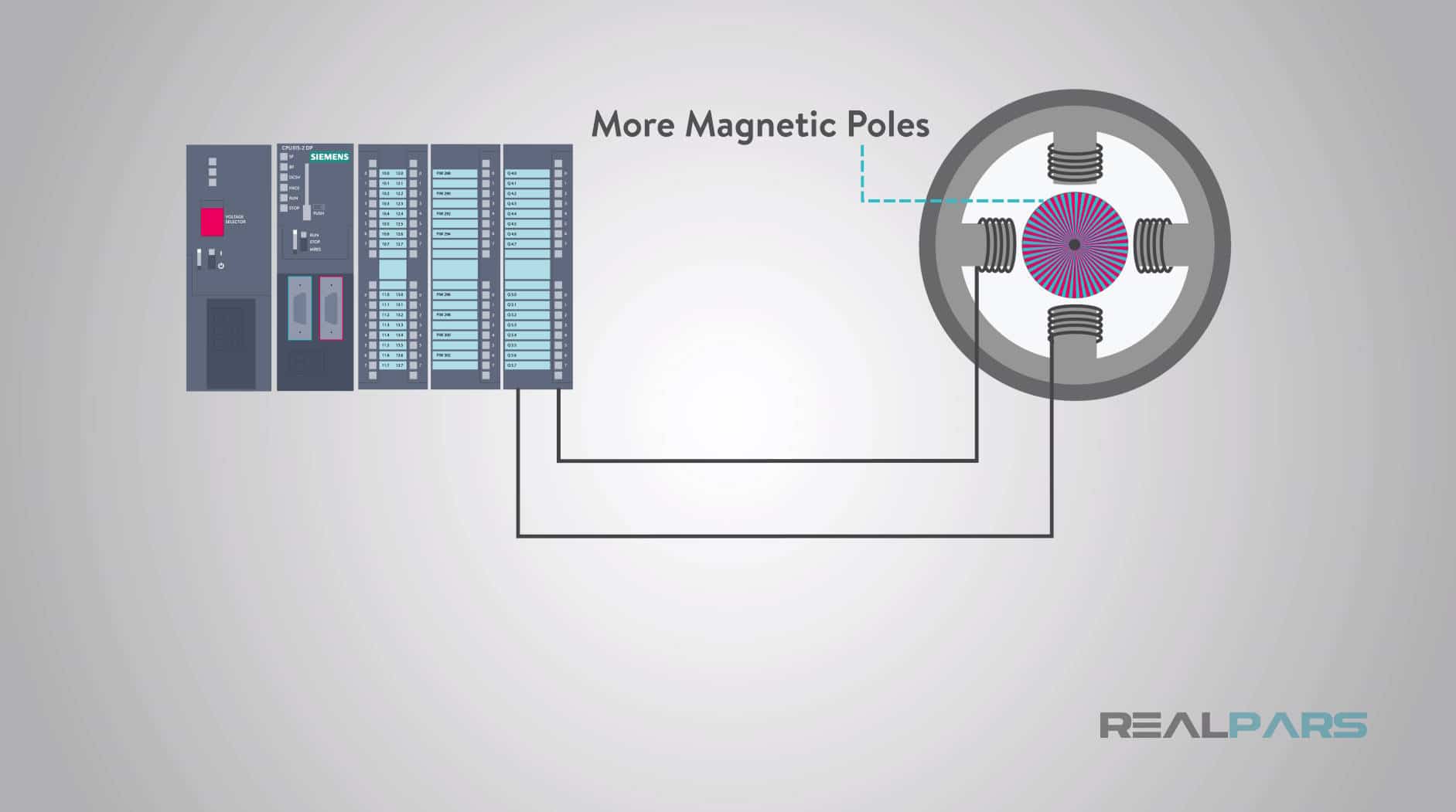
When we want to increase the resolution or achieve the smallest rotational movement, the design of the stepper will contain a larger number of magnetic poles.
Basically, the incremental step size of a stepper motor is fixed to a certain degree of rotation based on the number of electromagnet poles. Therefore, moving to an accurate position is simply a matter of sending the correct number of pulse commands.
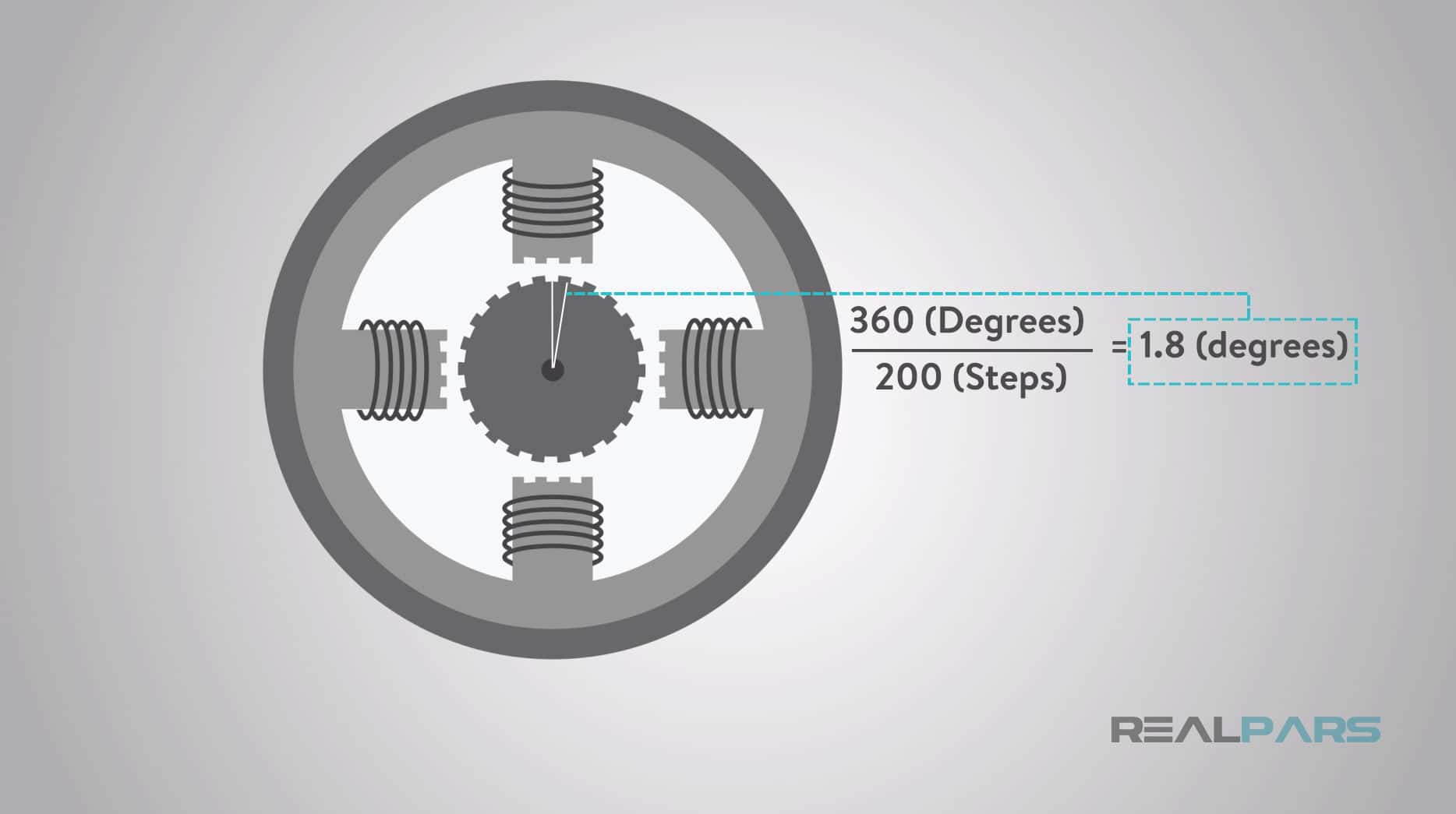
Stepper motors may have up to 200 rotor teeth, or 200-400 full steps per revolution of the motor shaft.
To determine the resolution of rotation we can perform a little math. If a stepper motor has 200 incremental steps and we know a full rotation is equal to a circle or 360-degrees then we can divide 360-degrees by 200. This equates to 1.8-degrees of a full step angle rotation.
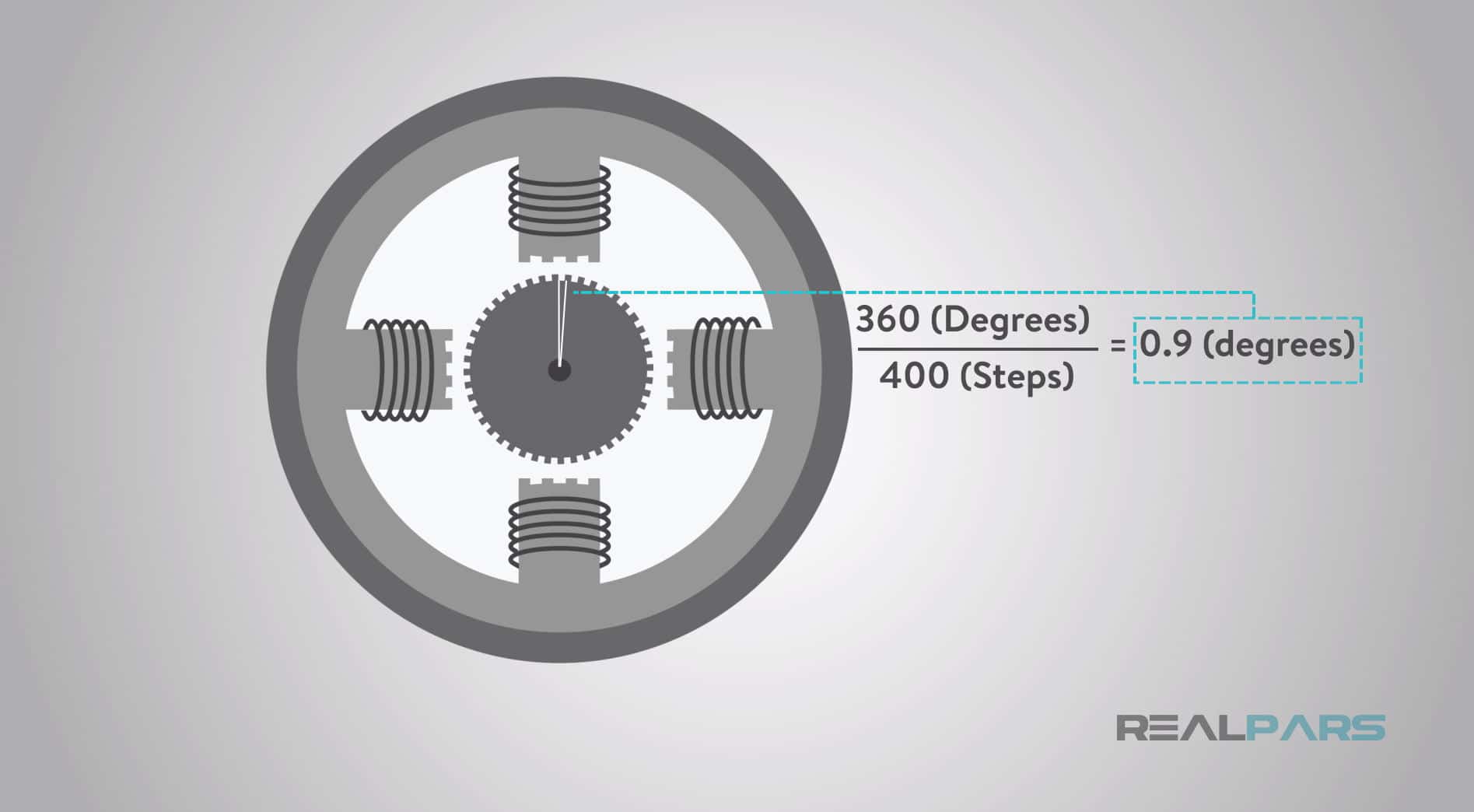
400 steps divided into 360-degrees provides 0.9-degrees of full step angle rotation.
Outputting one digital pulse from the controller driver is equivalent to one step of rotation.
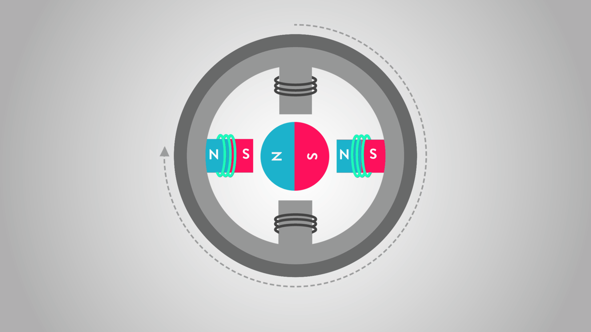
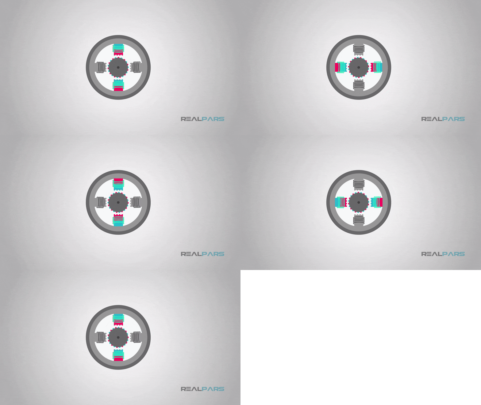
Now let’s follow a simple movement diagram of a stepper motor to determine how the stepper motor works in one complete rotation.
At position 1, the rotor is started at the top electromagnet pole, which is currently energized with current flowing through the wire.
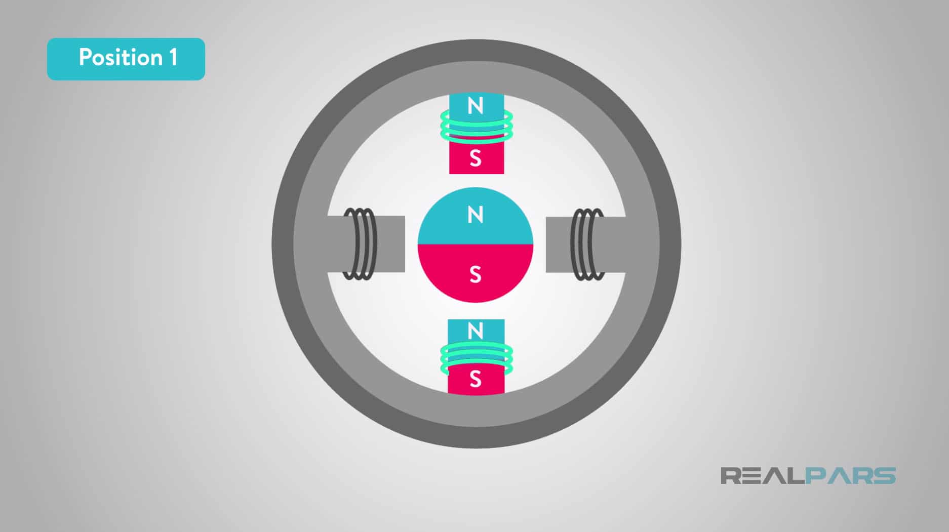
Now in order to move the stepper rotor clockwise (CW) the top electromagnet pole is deactivated and the right electromagnet pole is activated causing the rotor to move 90 degrees clockwise and align with the active magnet as shown in position 2.
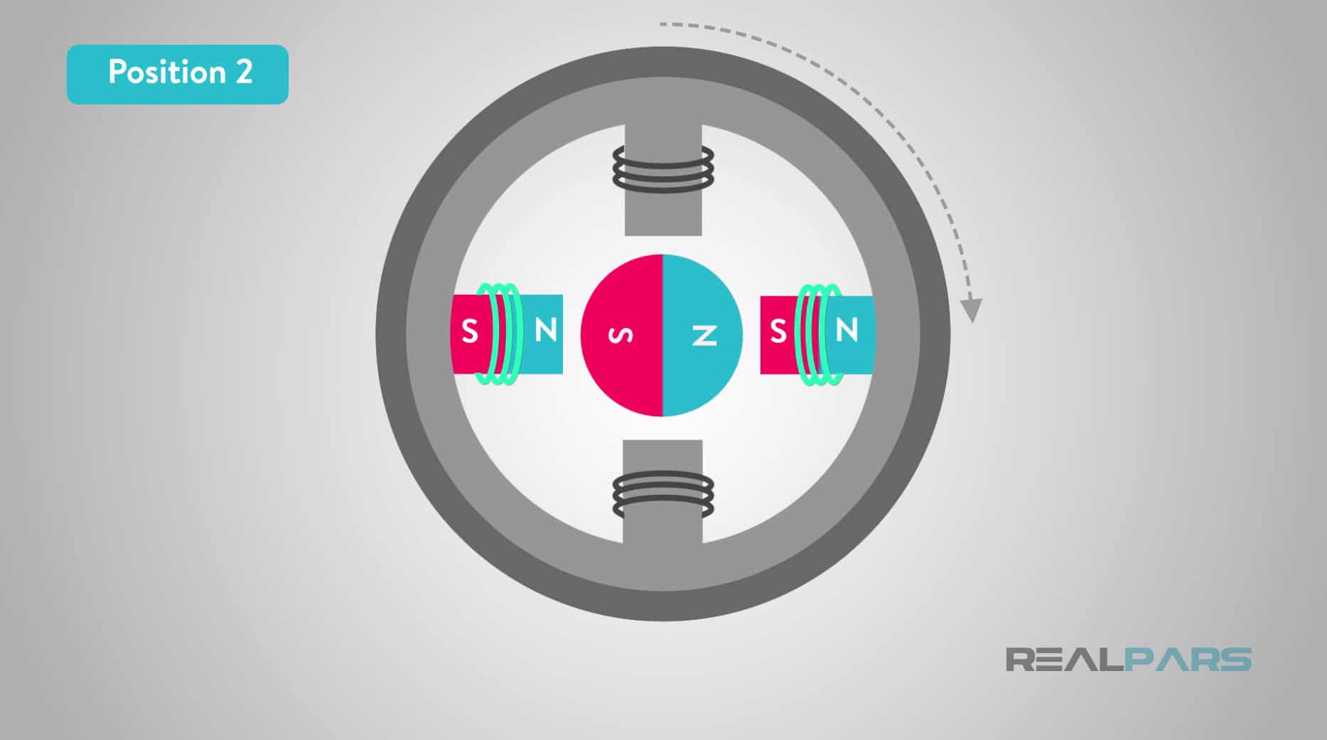
Now as we continue to deactivate and activate the electromagnet poles around the stator in positions 3 and 4 causing the rotor to re-align with each new electromagnet pole we enable the rotor to rotate 90 degrees clockwise each time, this eventually completes a full 360-degrees of rotation.
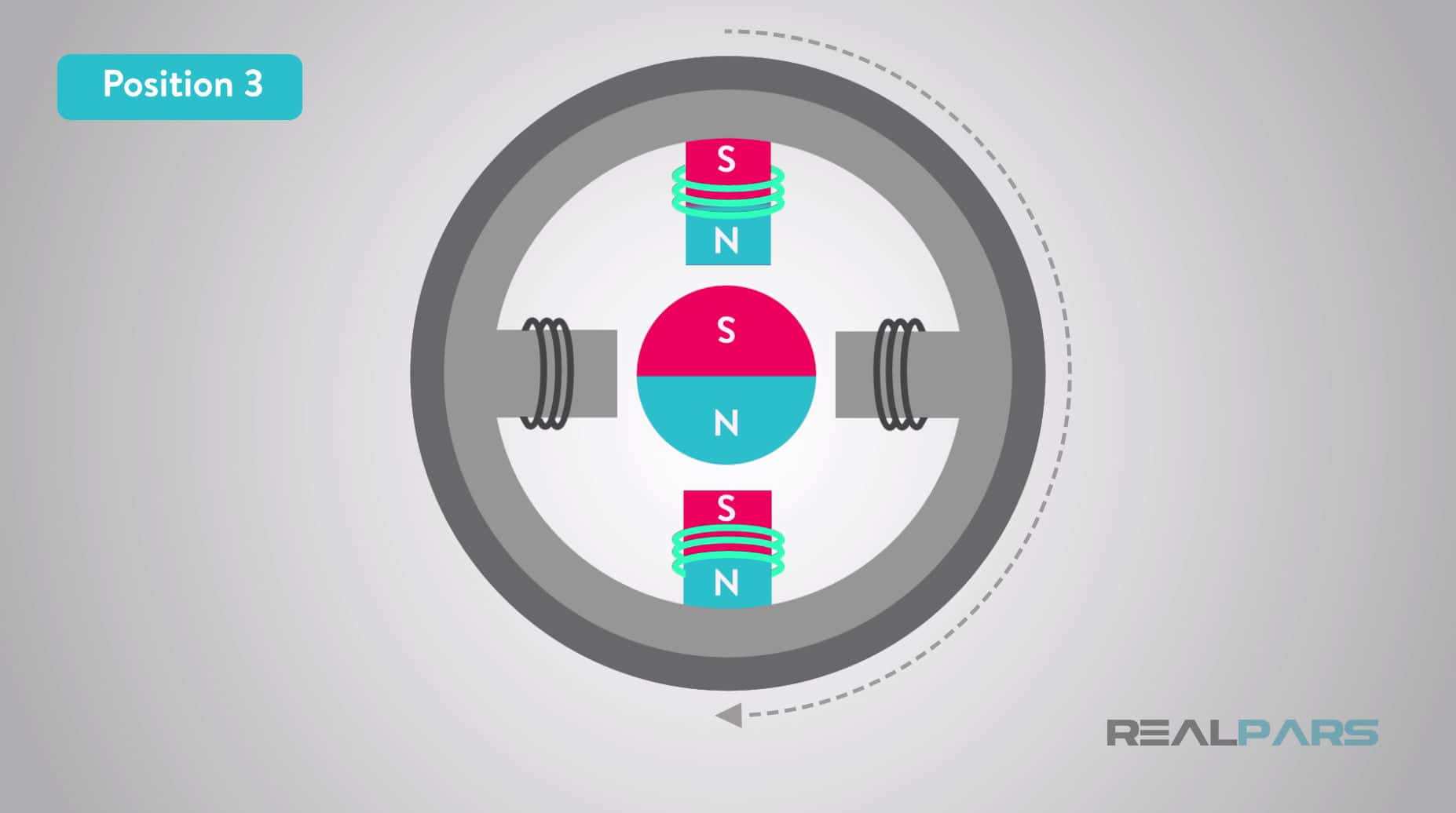
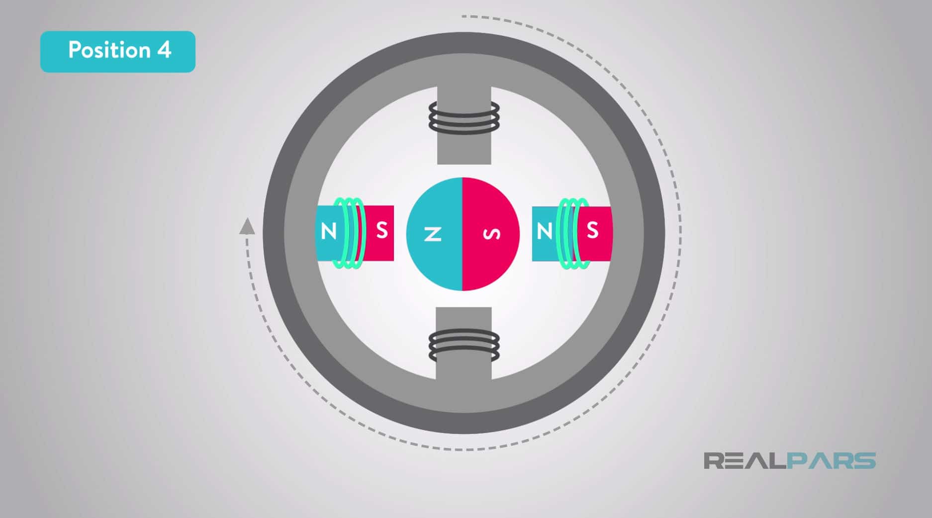
Hint: Remember how like magnetic poles repel and unlike poles attract. Depending on whether is applied to electromagnetic pole coil wire we can cause LIKE and UNLIKE magnetic attraction and reattraction forcing the permanent magnet rotor to move.
In the real-world stepper motors incorporate a larger number of electromagnet poles on the stator and rotor to increase the resolution as we have discussed earlier.
With this increase in the number electromagnet poles the operation is basically the same as the example provided using 90-degree rotation but now the rotation would be more like 1.8-degrees of rotation as mentioned earlier.
An example of a multi-pole stepper motor is illustrated here.
In position 1 the rotor is aligned in the upper position with the top stator electromagnetic activated indicating S for South polarization and in position 2 the top electromagnet stator is de-energized and the electromagnet stator to the right is energized the rotor moves clockwise and aligns with this electromagnet indicating the new S polarization allowing for a precise rotational movement of degrees.
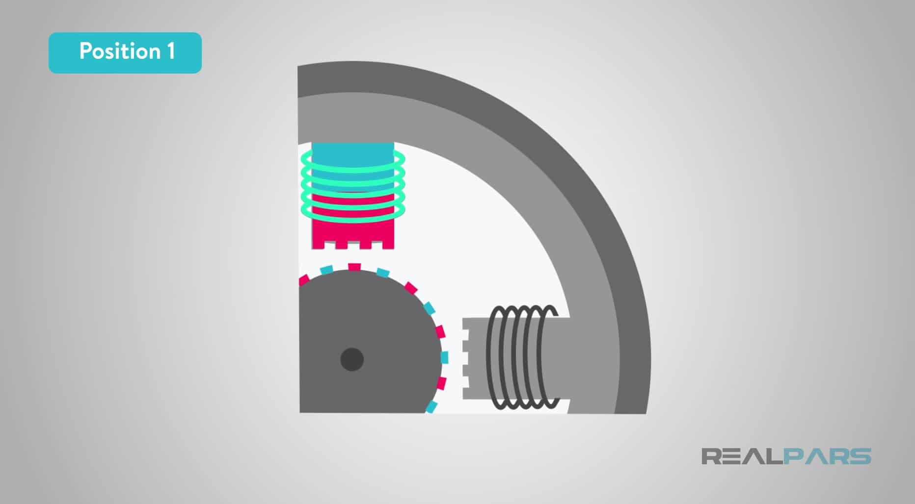
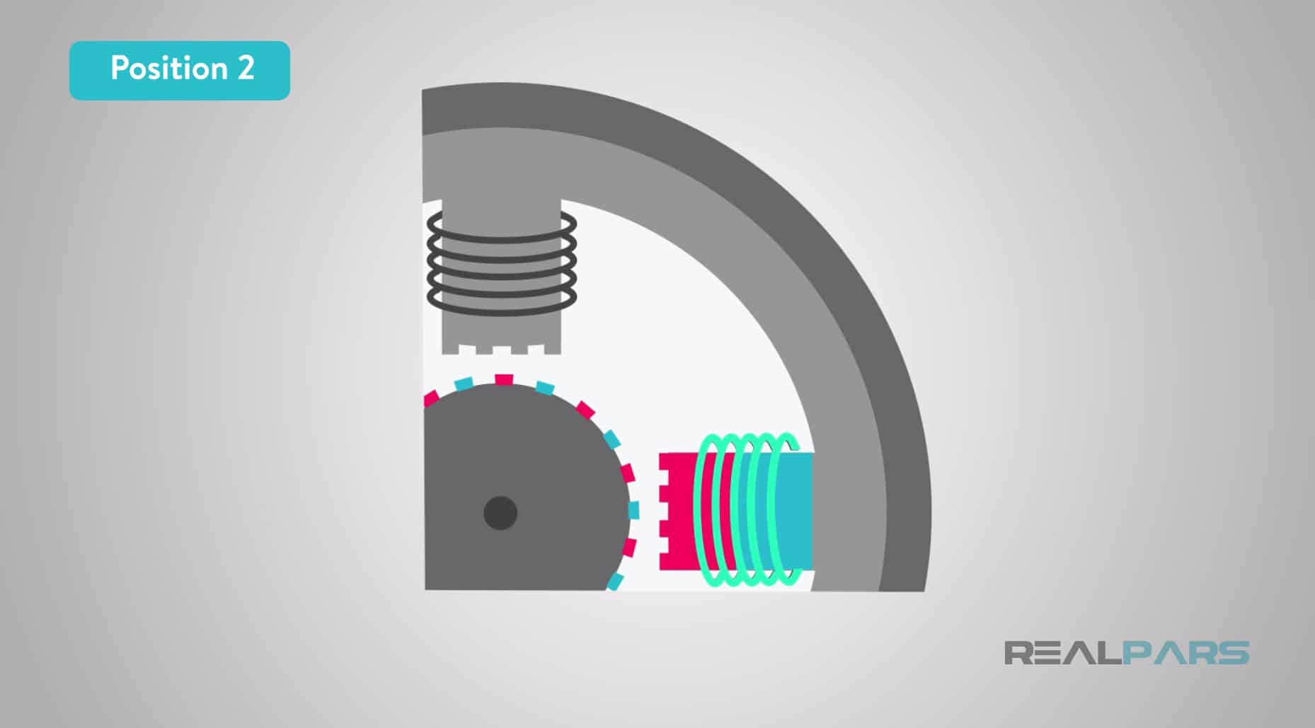
This changing of the electromagnetic polarization continues creating 360-degree rotation. The faster the electromagnetic polarization occurs the faster the speed.
This concludes the article, What is a Stepper Motor and How Does a Stepper Motor Work? I hope you have learned what’s required to move forward in creating your own motion control project.
If you enjoyed this article, please share it with friends and colleagues. This article is one of a series of articles on motor and motion control, so please check back with us soon for more motion control topics.
With endless love and gratitude,
The RealPars Team
Frequently asked questions
Learn from Industry Experts
With a 7-day trial, then €35/month