

I hope you have been following our lessons on Motion Control related topics. Recently RealPars have published blog post lessons on what are Servo and StepperMotors and how they work. I hope you have a had an opportunity to read.
Now that we have learned about Motion Control motors, we can begin to apply this knowledge towards Motion Control applications.
In this lesson we discuss what is Linear Motion Control and a few real-world applications with respect to linear motion, positioning systems and actuators used with stepper and servo motors.
Linear Motion Control in part depends much on the actuator and the linear actuator covers a broad range of products.
A linear actuator is a mechanical device that converts energy such as the power from air, electricity or liquid to create motion in a straight line and it may be used to apply a force.
In this lesson we will focus on how the electrical-mechanical aspects of linear motion control are applied when using stepper or servo motors.
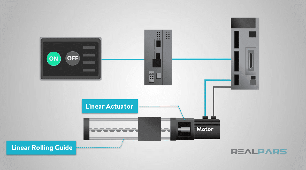
Linear motion is an area of motion control encompassing several technologies including linear motors, linear actuators, and linear rolling guides and bearings.
Linear control systems and actuators are used in industrial automation and machinery, machine tools, computer peripherals such as disk drives and printers, home automation, packaging, assembly, medical imaging and diagnostics, electronic manufacturing, industrial test and inspection and robotics applications.
Linear drives move the carriage to the desired positions.
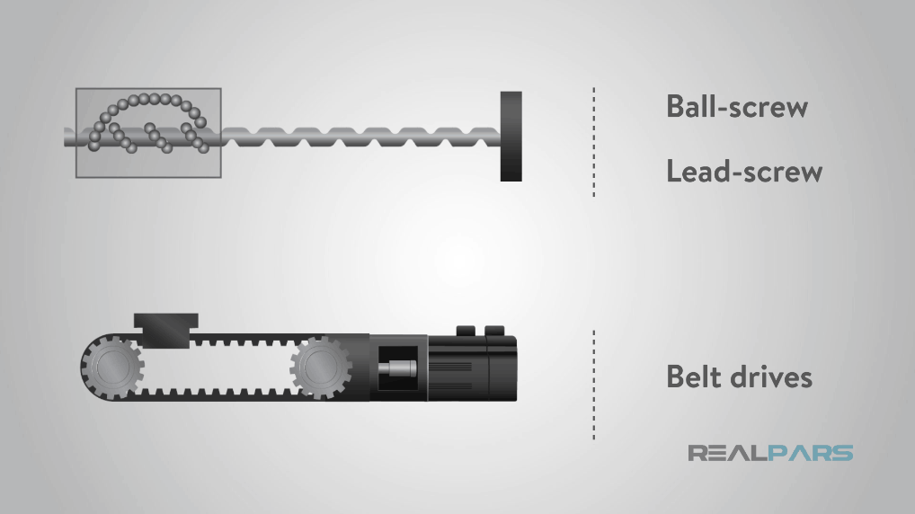
The most common drive technologies are ball-screw drives, lead-screw drives, and belt drives.
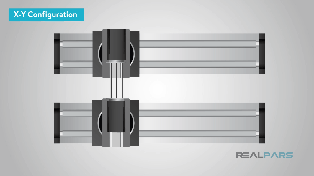
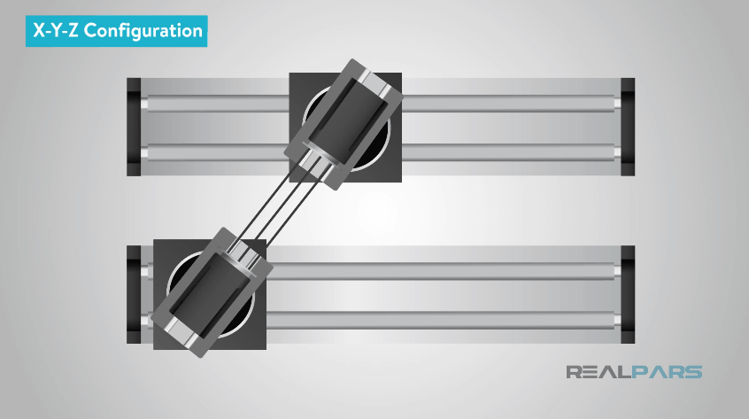
Linear Motion control system configuration, including the number of axes of motion, is often the first factor that needs careful thought.
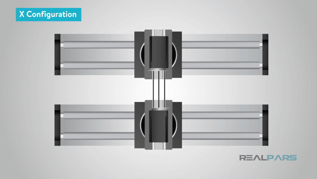
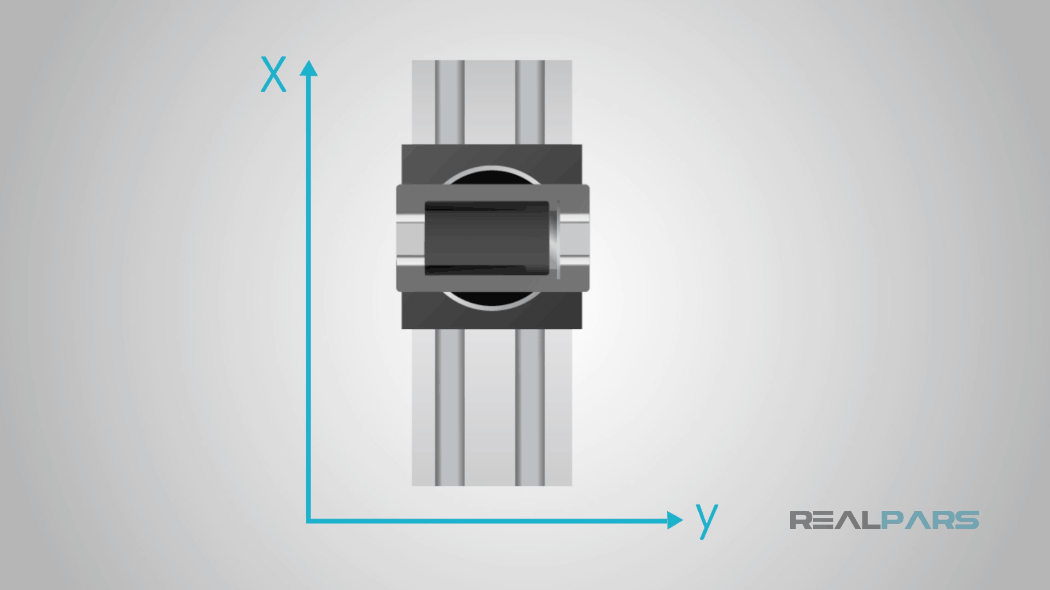
The most common are two-axis (X-Y) configurations, but less complex single-axis applications and three-axis configurations are also possible.
Many factors need careful consideration when selecting a suitable linear motion control system for a single-axis, two-axis or three-axis positioning system.
System orientation and mounting are key factors.
In a single axis linear system, this is fairly straightforward, but in multiple axis systems, this becomes more complex.
Factors to consider here include the direction of travel of each axis. Does the load need to be moved simultaneously in multiple axes or does each axis move individually and does the system require a moving carriage or a moving rail and are the axes vertical, horizontal or inclined and finally are the mounting positions of each actuator at 0, 90 or 180 degrees to the horizontal?
Additional specification when considering linear motion control design for an application are: force, speed, travel distance, accuracy and repeatability and lifetime requirements or the duty cycle and of the machine.
In determining how much force is required the weight of an object being lifted and or the amount of friction of that object needs to be overcome.
Knowing the mass of an object to be moved and its center of gravity as it moves relative to a coordinate point on each axis must also be calculated to determine the force requirement. This calculation needs careful consideration so that the moment loads or the turning effect of a force at multiple points in the system can be established.

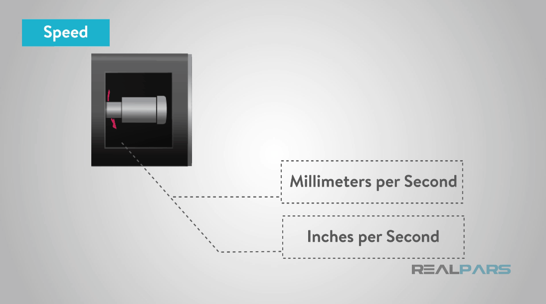
Next, you’ll need to determine the speed on how fast in millimeters per second or inches per second the actuator will need to move.
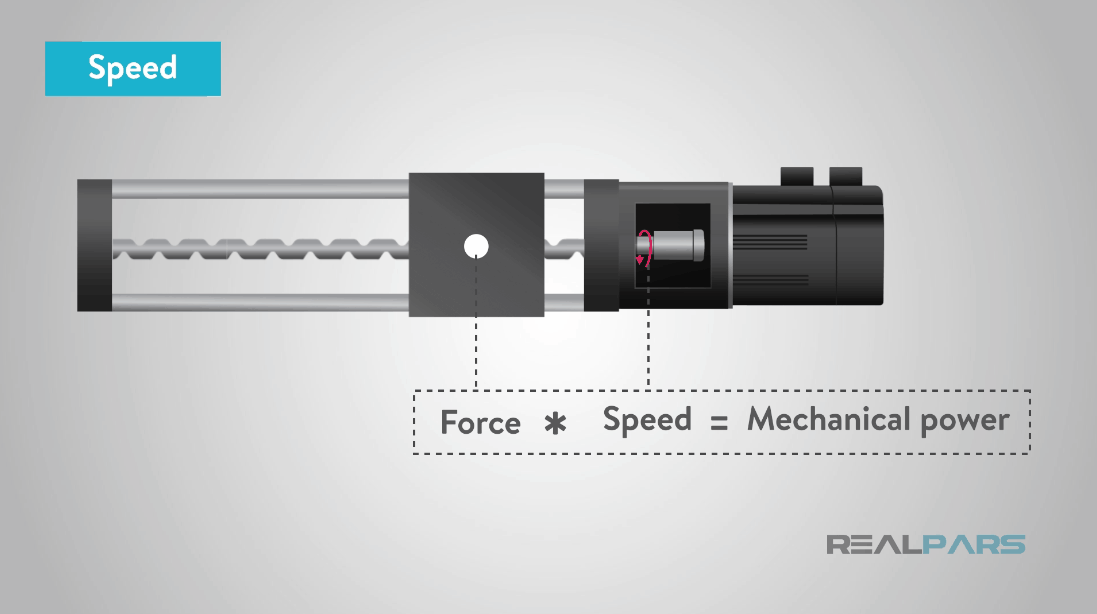
Determining the speed combined with the force will give you the mechanical power required and how powerful the motor must be.
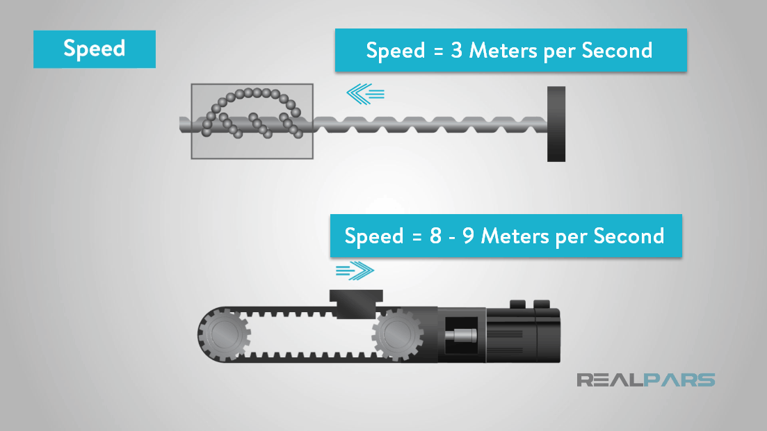
Traverse speeds and traverse times are somewhat limited with ball screw drives.
Ball screw actuators typically have a maximum speed of 3 m/s (meters per second) and for belt-drive actuators the maximum speed is around 8 – 9 m/s.
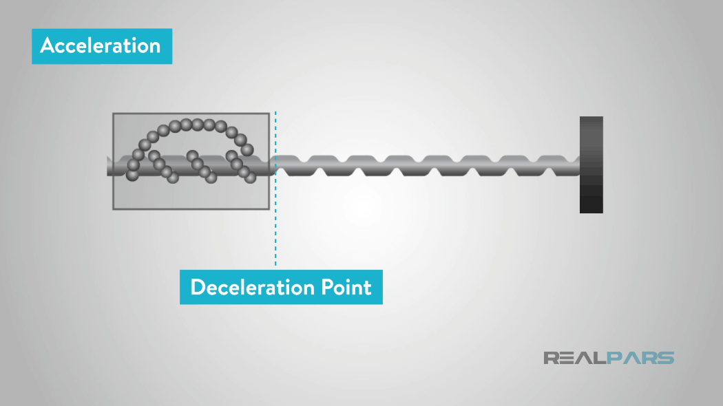
The highest acceleration of any linear motion control actuator is around 40m/s2(meters per second per second) however, typical accelerations are much less than this, often between 0.5 m/s2 and 5m/s2.
Deceleration is also important, especially if emergency stops required.
You’ll need to define how far your load or actuator needs to travel. This is known as the stroke length.
Many actuators come in standard sizes, it’s best to choose an actuator close in size to your requirements versus having a custom actuator built to save cost.
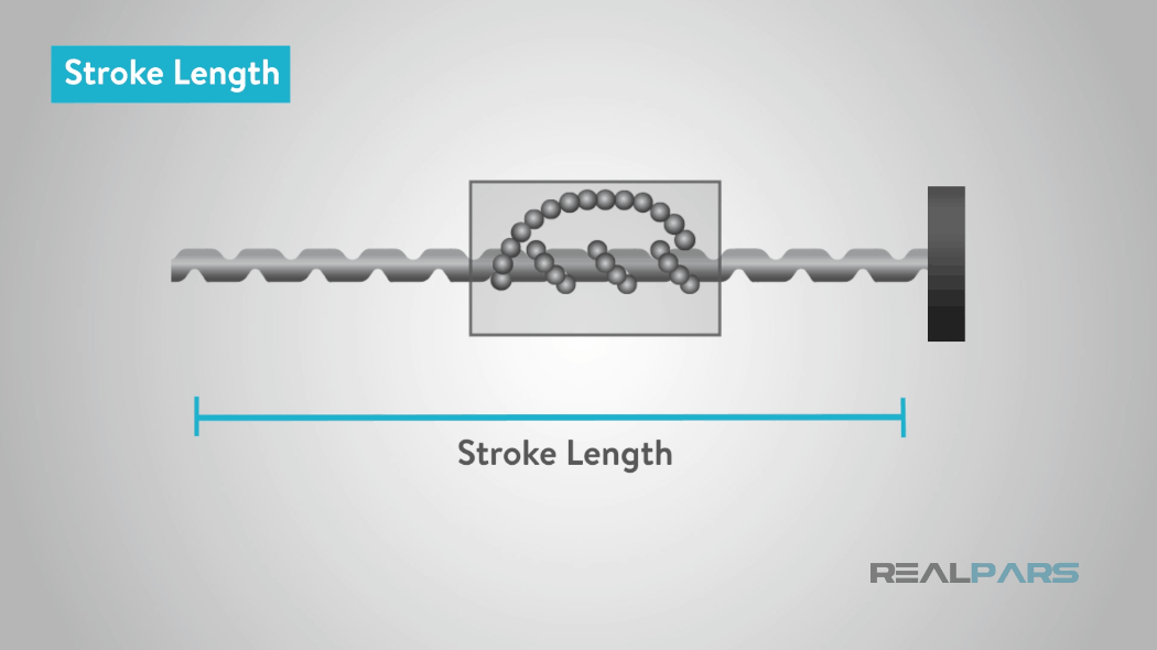
Knowing the total stroke length for each axis is critical when specifying your system requirement and will help in determining the correct type of linear motion control drive system.
With ball screw linear actuators, for example, the stroke length is limited to the length of the ball screw itself. Therefore, maximum stroke lengths tend to be around 3 meters.
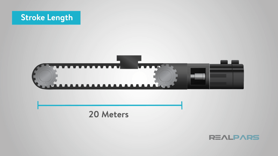
But with belt-driven systems, there are no such restrictions and so stroke lengths can be higher than this, up to as much as 20 meters if required.
If linear motors are specified, the stroke length is unlimited normally around 10 meters.
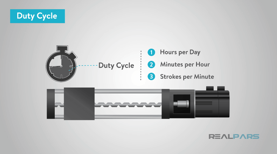
In addition, you will need to determine life time requirements or the duty cycle.
Duty cycle is defined in how often the actuator will operate and how much time will elapse between movements.
Duty cycle is based on the number of expected repetitions per unit of time in hours per day, minutes per hour, and/or strokes per minute.
Cycle times determine the life of a linear motion control system.
The repetitive motion of back and forth or up and down movements produces friction and this friction creates wear and tear on the system components.
This cycle time or duty cycle is critical criteria in determining the operating life on just how long you want your systems investment to last.
Accuracy and repeatability are one of the most considered overall for the system, in which may deliver the desired quality or precision required in the system or manufactured end product.
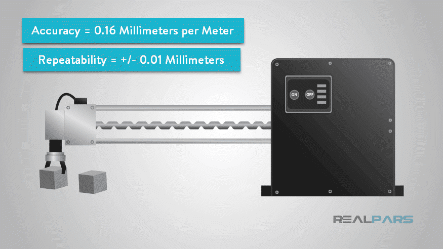
If the application for example is for an automated pick-and-place machine, high repeatability and accuracy are most likely required.
Typically, the accuracy of a ball screw linear actuator is 0.16 millimeters per meter with repeatability of +/- 0.01 millimeters.
For belt-drive actuators the accuracy is around 0.5 millimeters per meter, with repeatability of +/- 0.10 millimeters.
Other considerations are whether to use limit switches or feedback devices such as potentiometers and encoders for positioning purposes.
There are many linear type actuators to choose from such as, for example, screw actuators, and belt actuators.
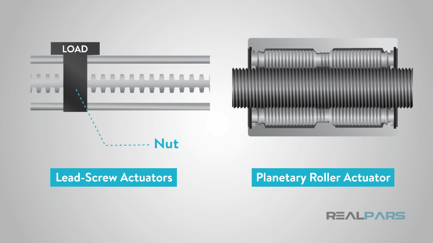
Screw actuators include lead-screw actuators, ball screw actuator and planetary roller actuators. Lead-screw actuators having a threaded nut that moves with a screw.
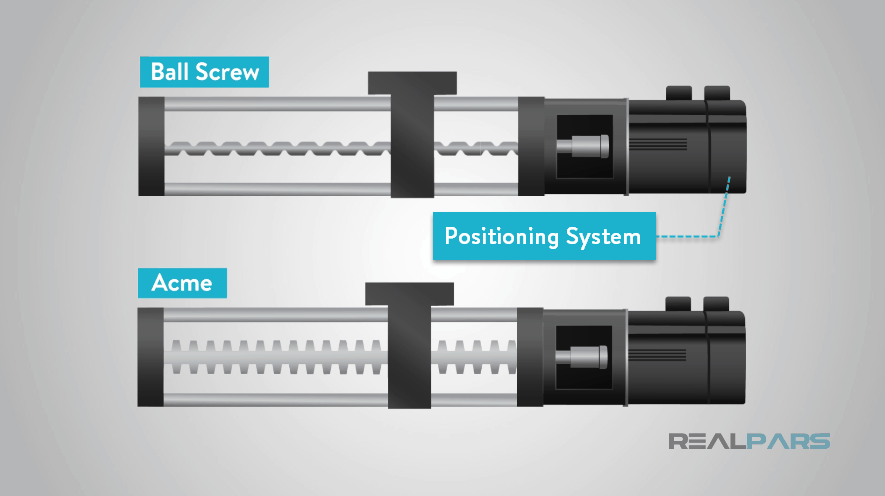
Screw driven positioning systems are used in applications where accuracy and repeatability are more critical.
These positioning tables use either an acme or ball screw as the drive mechanism.
Bearings are used to carry the load of the application.
Lead-screw solutions provide both simple construction and lowest cost.
Many electro-mechanical designs incorporate a lead-screw and lead nut, while some use a ball screw and ball nut.
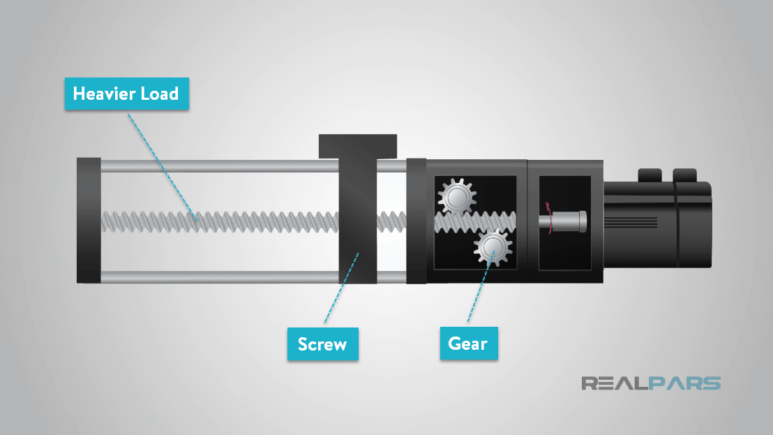
In either case, the screw may be connected to a motor either directly or through a series of gears.
Gears are used to allow a motor to be geared down to provide torque necessary to rotate the screw under a heavier load the motor would be capable of controlling directly.
Rotary motion of the motor is converted into linear displacement of the actuator.
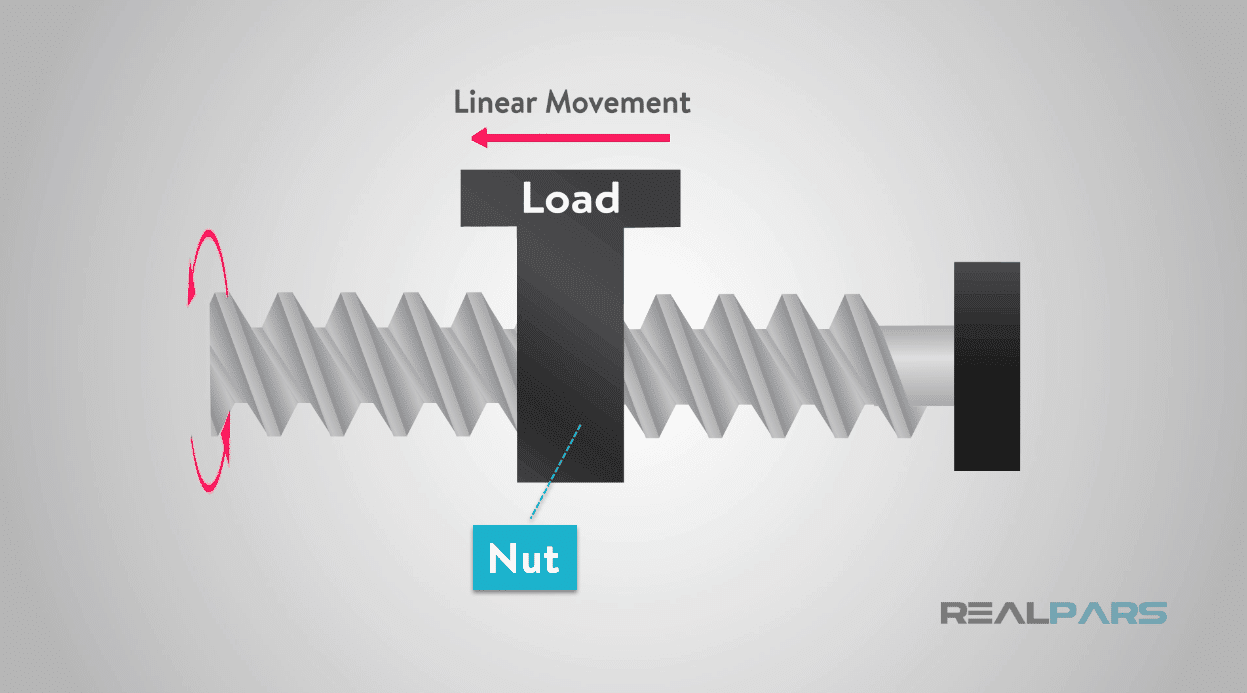
A lead-screw has a continuous helical thread machined on its circumference running along the length, similar to the thread on a bolt.
Threaded onto the lead-screw is a lead nut or ball nut with exact helical threads. The nut is normally fixed and prevented from rotating with the lead-screw.
When the lead-screw is rotated, the nut is driven along the threads.
The direction of motion of the nut will depend on the direction of rotation of the lead-screw.
Connecting the load to the nut, the motion can be converted to usable linear movement.
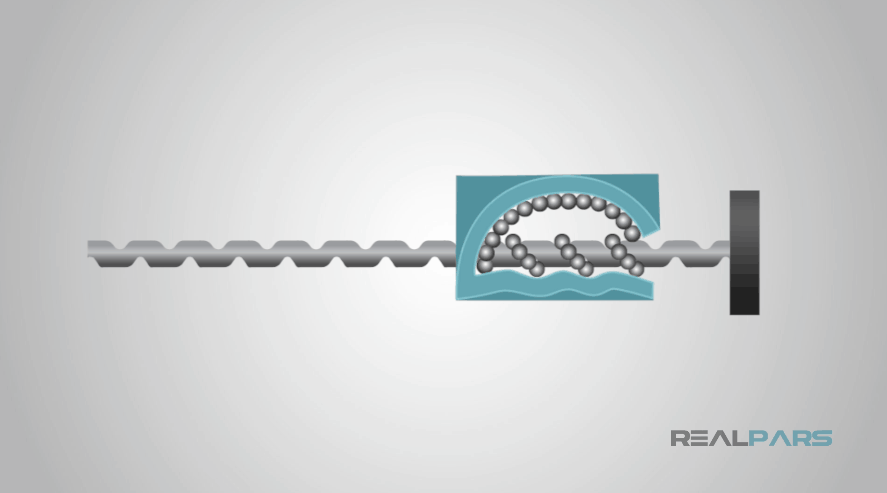
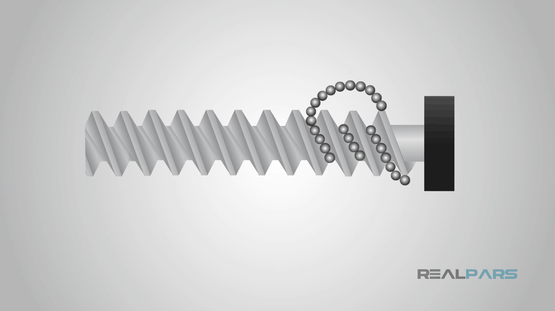
Ball screw actuators use ball bearings and are more expensive but provide less friction compared with lead-screw actuators.
In a ball-screw drive, ball bearings travel along the grooves in a threaded shaft and the ball screw and recirculate through a ball nut.
Because bearings share the load, ball-screw linear motion drives have relatively high thrust capacity.
A ball-screw drive combines repeatable motion and a stiff system that handles high forces and moments.
Such systems work well in precision-positioning applications with high loads and high duty cycles.
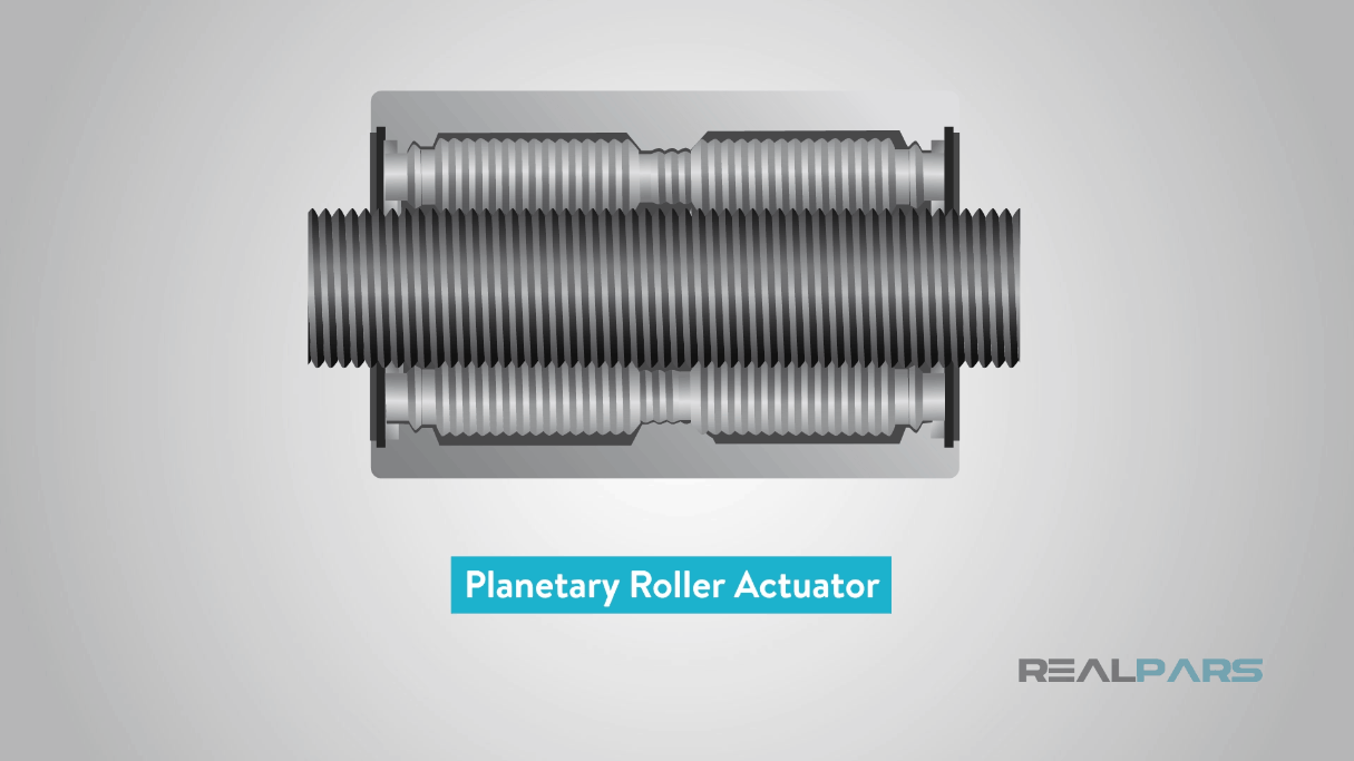
Planetary roller screw actuators use threaded rollers surrounding the main threaded shaft is the most expensive option but also the most durable.
Belt driven linear positioning tables are based on using belt drives and in high speed and or long travel positioning applications where a screw actuator are not practical, normally in stroke lengths over 6ft.
The belt and pulley drive mechanism provide modestly repeatable high-speed positioning.
Belt drives are quiet and good for high-throughput, lower-precision applications. More-expensive ball-screw drives provide high efficiency, accuracy, and stiffness.
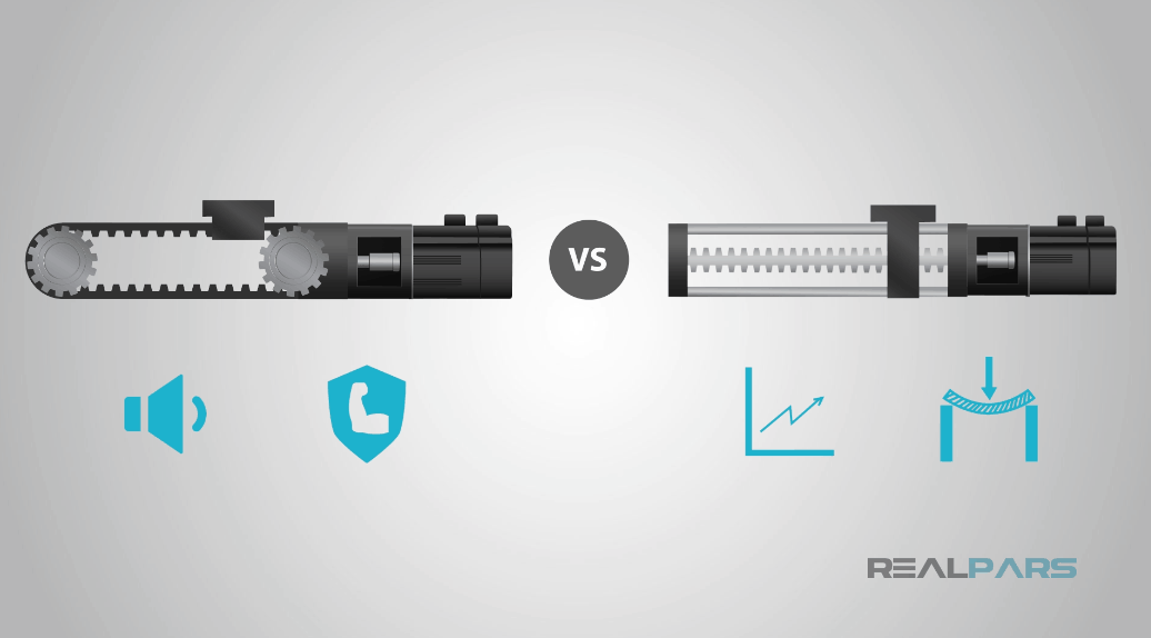
Belt-driven, ball-guided units are for high-speed, high-acceleration applications with heavy payloads and high moment loads.
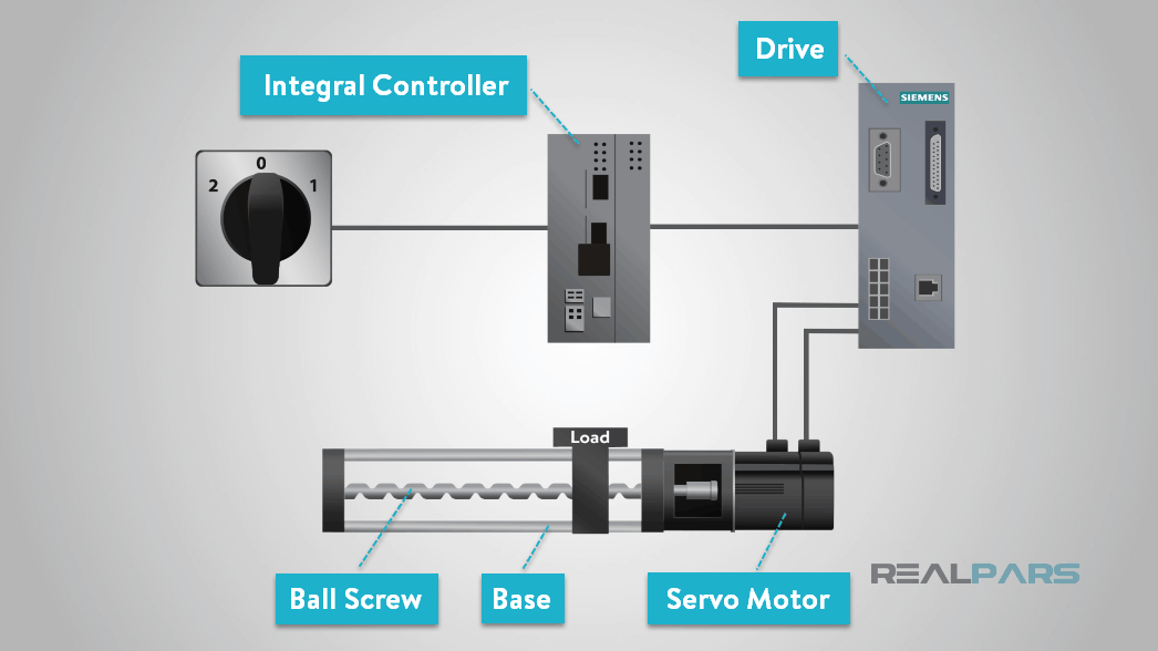
Integrated linear motion control positioning systems are easy to use and can be acquired as a turnkey system.
Most of these preconfigured positioning systems are comprised of base, ball screw, and a servo/stepper motor with integral controller and drive for rapid machine commissioning and ease of operation.
There are many companies in the linear motion control market providing complete solutions for a variety of linear motion control applications.
These companies will provide engineering support for motor sizing and turn-key linear actuator recommendations.
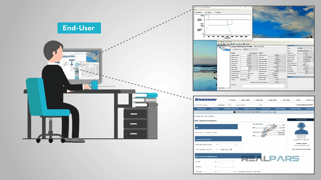
There are many vendors providing software products that will help the end-user or OEM with the design and selection process of a stepper | servo motor and a linear actuator.
Knowing what we discussed in the lesson will help you with the information required in the system selection process.
For example, these pictures of a software program illustrates, after answering a few questions, the motion profile plot and the motor requirements of a system.
Examples of Linear Motion Control applications for industrial machines are used with positioning loads, palletizing, packaging, pick and place operations, filling operations and automated warehouses.
You’ll also find linear motion used in cutting machines and painting machines.
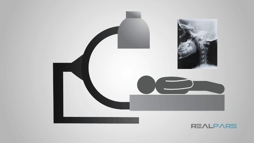
Linear motion for medical application uses such as in operating room beds, X-ray machines, MRI and CT Scanners as well as dentist chairs.
Linear motion for medical diagnostics and treatment used in scan heads and patient tables.
Other areas include Oncology, Nuclear Medicine, CT/MRI/Imaging, Portable Respirators, and Surgical Robotics.
Linear motion in medical lab automation used for pick and place, DNA sampling, Cell culture, Air displacement Drug testing, and Drug dispensing.
It is critical in these applications to have good reliability and low to zero maintenance to help minimize downtime and maximize clean operation and speed.
Successful lab automation operation can reduce end user costs and speed delivery of medical products.
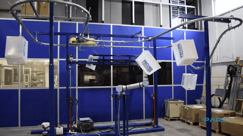
An overhead conveyor system is a convenient solution when an assembly line requires a steady flow of materials to key assembly areas along the line.
This conveyor system can also be used to position assembly tools and equipment.
The benefits of this quick pace system normally found on an assembly lines assists operators moving equipment accurately and lowers the overall risk of fatigue and injuries.
The food industry places high demands on material handling equipment.
Harsh conditions found in places such as dairies, bakeries and breweries suggest equipment is exposed to extreme temperatures, water splash down, dirt and cleaning agents.
The equipment is required to be fast and accurate to keep up with high speed production lines. These are just a few of the many applications used in many industries.
This concludes the blog post, what is Linear Motion Control? I hope you have learned what’s required to move forward in creating your own motion control project.
This blog post is one of a series of videos on motor | motion control, so please check back with us soon for more motion control topics.
We at RealPars hope that you found it interesting, and that you will come back for more of our educational blogs.
TONS love and excitement,
The RealPars Team