

In this article, we’re going to talk about the PID Controller and its transformation from a single station device to what it has evolved into today.
We’re going to explain why PID Controllers are used in industrial processes instead of simple ON/OFF Controllers.
We’ll illustrate how Controller settings called Proportional, Integral and Derivativeaffect different processes under control.
We’ll also provide an overview of the very important activity called Controller Tuning.
Process control is sometimes called analog control because it involves controlling analog loops, like the temperature of a tank. And at the heart of almost every one of those loops is a PID controller.
A simple example
Let’s start with a discussion about home temperature control as it’s familiar to lots of people.
This house has a furnace that distributes heat throughout, and a wall-mounted controller called a thermostat.
The thermostat has a sensor that measures the house temperature and compares that measurement to an adjustable setpoint.

If the room temperature is below the setpoint, the furnace is turned ON.
When the room temperature increases above the setpoint, the furnace turns OFF. This type of control is referred to as ON/OFF or Bang-Bang Control.

Below is a plot of what the room temperature does over a period of time as the furnace turns ON and OFF.
As you can see, the temperature is not exactly held at the setpoint of 70°F, but cycles above and below the setpoint.

ON/OFF control may be ok for your house, but it is not ok for industrial processes or motion control.
An industrial example
Let’s look at an example of tank level control to explain why. The Valve fills the tank as the pump drains it. If the valve is operated with ON/OFF control, the water will fluctuate around the 50% setpoint.

For our purpose, let’s say the fluctuation is ±10%. In most industrial applications, this fluctuation around the setpoint is not acceptable.
OK, well, what if it’s possible to throttle the valve and place it in any position between ON and OFF?
PID controller
Now we can move on to talking about a PID Controller. P stands for Proportional, Istands for Integral, and D stands for Derivative.
Because every process responds differently, the PID controller determines how much and how quickly correction is applied by using varying amounts of Proportional, Integral, and Derivative action.
Each block contributes a unique signal that is added together to create the controller output signal.

Each part has its own gain factor: Kp for the proportional part, Ki for the integral part, and Kd for the derivative part. This gain defines how strong the reaction of the controller will be in response to an error.
Feedback control loop
Let’s look at how a PID Controller fits into a feedback control loop. The Controller is responsible for ensuring that the Process remains as close to the desired value as possible regardless of various disruptions.
The controller compares the Transmitter Process Variable (PV) signal, and the Setpoint.
Based on that comparison, the controller produces an output signal to operate the Final Control Element. This PID Controller output is capable of operating the Final Control Element over its entire 100% range.

PID controller logic block
Most modern PID Controllers are part of a PLC or DCS and are created in the program control logic using block commands.

Evolution of PID controllers
Many automation and control folks credit Elmer Sperry for inventing the simple feedback PID controller in 1911. Elmer created a system to control a ship's rudders to help prevent it from sinking due to waves and other external forces.
The first practical industrial PID controllers emerged in the 1940s, such as the Foxboro 43P pneumatic controller.
The introduction of electronic PID controllers, such as the FOXBORO SPEC 230SM CONTROL STATION, led to the widespread use of PID control in process industries.
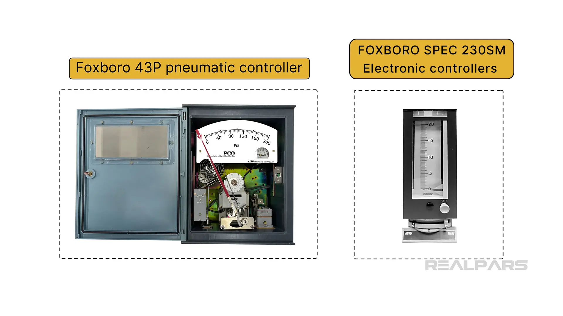
Stand-alone PID controller
Before PLCs came along, a PID controller was a stand-alone device responsible for controlling one loop.

PLCs and DCS control systems
Today, we have PLCs and DCS platforms that are capable of managing multiple processes via centralized control, resulting in faster data processing and analysis.
For example, the AB Controllogix PLC 1756-IF8 analog input module can receive process measurement data from up to 8 separate processes. PID control is managed via the RSLogix 5000 programming language, or the newer version Studio 5000 Logix Designer.
A DCS is a computerized control system with multiple autonomous controllers that operate and control many control loops.
Field devices are connected to Controllers with multiple I/O modules located in cabinets. The controllers are networked using many communication protocols, such as Ethernet or Modbus. Operator station HMIs are located in a centralized control room.
The Operator station allows plant operators to observe and adjust real-time plant conditions. An engineering station HMI is located in an area only accessible for actual control logic programming changes for any of the many control loops.
Here's an example of a Yokogawa Centum VP HMI display. The Level Indicator Controller (LIC501) is set to Manual mode and currently shows a reading of 0%. The controller's output operates a valve XV522.
- Yokogawa Centum VP HMI display which shows the Level Indicator Controller (LIC501) is set to Manual mode and currently shows a reading of 0%
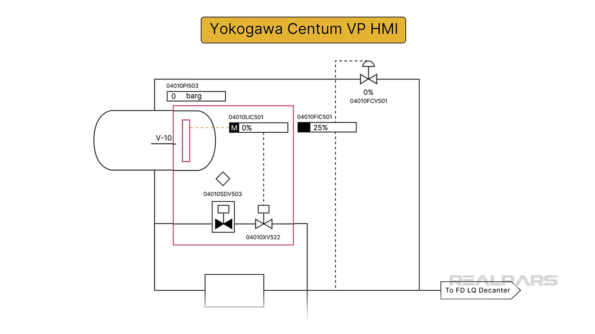
How is a DCS controller shown on a P&ID?
We draw a square box around the discrete standalone symbol to indicate a DCS controller.
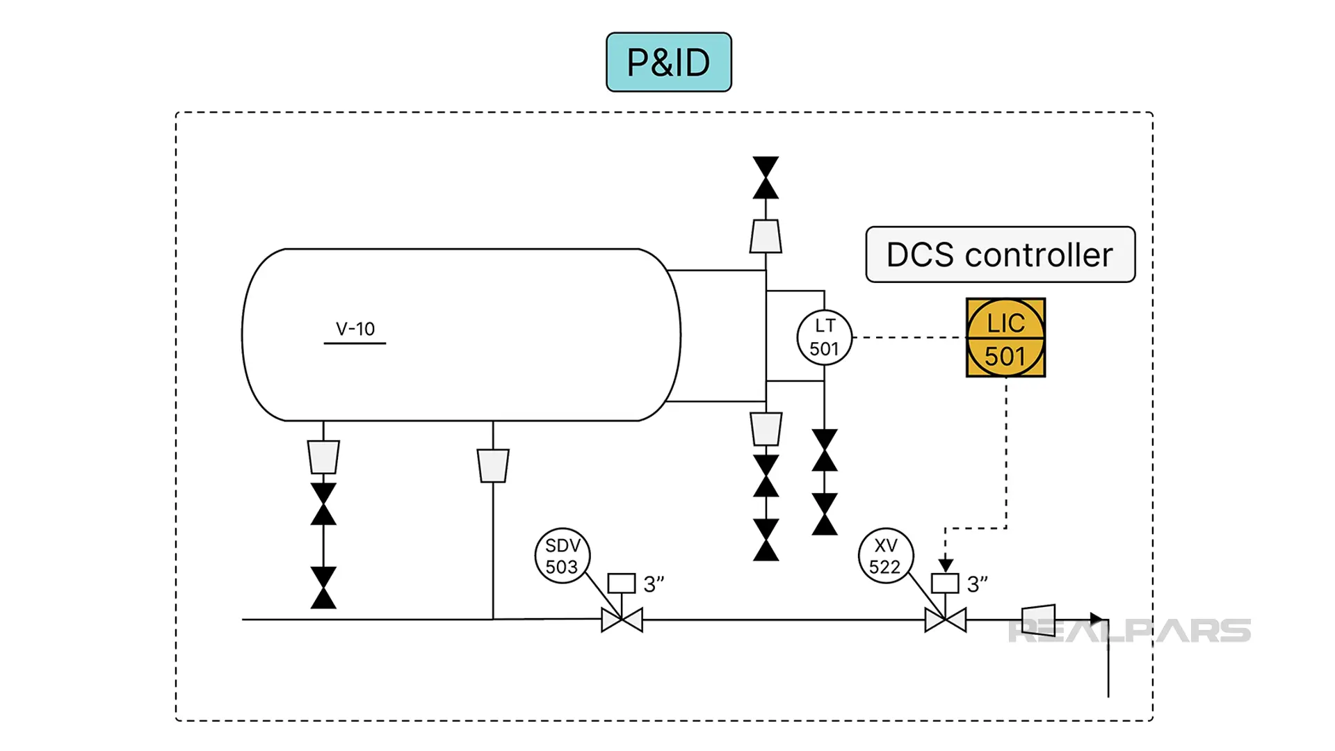
A simplified P&ID from our Yokogawa example shows the level controller and the valve XV522.
Of course, not all DCS HMIs have the same appearance.
Controllers on a Foxboro IA DCS HMI are designed to resemble the face of a traditional single-station controller.
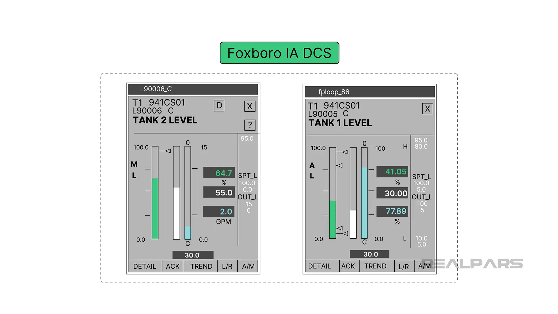
PID controller parameters
A control room would have dozens or hundreds of stand-alone controllers mounted on a panel.
There are still many stand-alone PID controllers being manufactured and used today.
OK, let’s get back and talk about what each of the P, I, and D components of the PID controller does.
Remember earlier we said that the PID Controller is responsible for ensuring that the Process remains as close to the setpoint as possible regardless of various disruptions.
Let’s refer to the difference between the Process Variable and the Setpoint as the Error signal.

1) Proportional block
The proportional block creates an output signal proportional to the magnitude of the Error Signal.

Unfortunately, the closer you get to the setpoint, the less it pushes. Eventually, the process just runs continuously close to the setpoint, but not quite there.
%20(1).webp)
That’s when Integral jumps in.
2) Integral block
The integral block creates an output proportional to the duration and magnitudeof the Error Signal.
The longer the error and the greater the amount, the larger the integral output.

As long as an Error exists, Integral action will continue.

The downside is that if the integral gain is too large, it will strongly contribute to overshooting the setpoint.
3) Derivative block
The derivative block creates an output signal proportional to the rate of change of the error signal.
The faster the error changes, the larger the derivative output.

Derivative is the least understood, and the least used, of the three factors. In fact, a majority of PID loops in the real world are really just PI loops, using only the proportional and integral parts. That said, there are certain applications where the derivative plays a very important role.
Derivative control looks ahead to see what the error will be in the future and contributes to the controller output accordingly. That brings us to a term called Controller Tuning.

Which control mode should you use?
Before we answer that, there are two terms you need to know.
Noise is temporary error readings that don't reflect the true condition of the process variable.
Dead time is the amount of time delay between a disturbance and the control action that responds to it.
Now here's a rough guide to which control mode you should use based on the application requirements:
- Use proportional-only control when a small offset has no impact on the process.
- Use PI control when no offset can be tolerated, noise may be present, and excessive dead time is not a problem.
- Use full PID control when no offset can be tolerated, there is no noise present, and dead time is an issue.
Regardless of the control mode that you use, to get a PID loop working optimally, you need to tune the loop. Let's talk about what that means in the next section.
Controller tuning
We said earlier that every process responds differently and that the PID controller determines how much and how quickly correction is applied by adjusting Proportional, Integral, and Derivative action.
Controller Tuning involves correctly setting the controller P, I, and D values for specific process requirements. Interestingly, the correct settings achieved by Controller Tuning can differ vastly between processes because of specific requirements.

For example, after the controller has been tuned, a setpoint bump of one percent in a tank level control produces a quarter-wave damped response.
This type of response may be suitable in a tank-level process but could be disastrous in a motion control process.

Controller tuning methods
Open-loop vs closed-loop tuning
Tuning methods fall into two general categories: open-loop and closed-loop.
Open-loop tuning is the simple, fast method. You change the value of the control output by a fixed amount, then watch how the system responds. Because you're only changing the output, the system won't easily go out of control, and if it starts to exceed any of your desired values, you can quickly adjust the output back.
Closed-loop tuning is more complicated. Here, you change the setpoint, then analyze the performance of both the PID and the system. This method is sometimes used to fine-tune a system after you've already done open-loop tuning.
There are many different manual methods for tuning a controller that involves observing the process response after inflicting controller setpoint changes.
One method involves increasing the amount of setpoint change and repeating the procedure until the process enters a state of steady-state oscillation.

This method of tuning produces adequate results but is often impractical in many applications. For example, how practical is it to force the fluid level in a large tank to reach a steady-state oscillation?
Most process controllers, PLC, and DCS loop controllers sold today have Autotuning capability.
The PID controller learns how the process responds to a change in setpoint, and suggested PID settings.

Regardless of whether the initial PID parameters are derived from manual or auto-tuning methods, additional tweaking is often required by seasoned automation professionals to get the response desired.

Applications of PID controllers
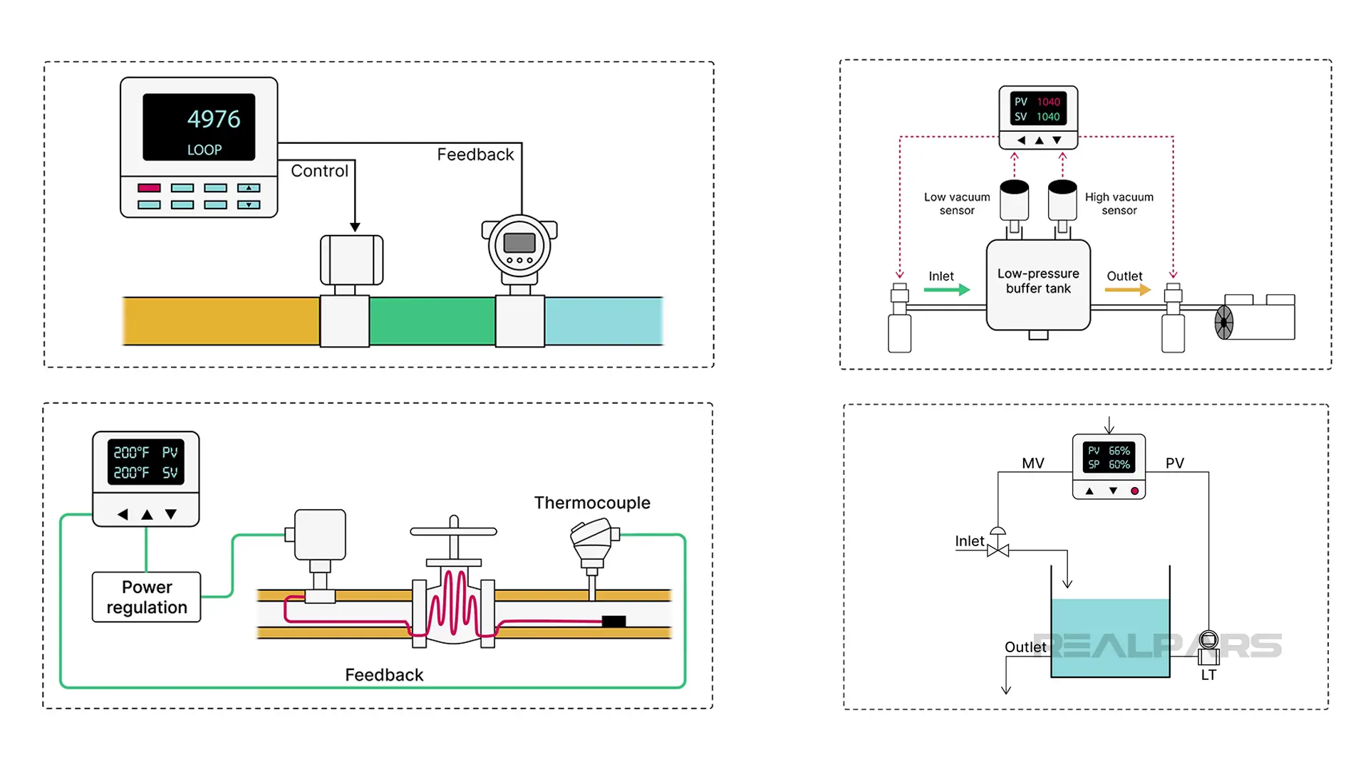
PID Controllers are used in almost all industries to control various process variables.
To name a few:
Temperature controllers are used in manufacturing to ensure precise temperature management, such as in food production and chemical processing.
Flow controllers manage the flow of oil, gas, and steam in pipelines, refining operations, and other production processes in the oil and gas industry.
Pressure controllers are used in Petrochemical Processing to manage pressures in distillation columns and separators.
Level controllers are often found in chemical processing plants. They are typically used to maintain liquid levels in tanks and vessels within a specific range.
Other control methods
Hopefully, we haven't given you the impression that PID controllers are the only choice for process control in the industry.
Other control methods include Fuzzy Logic Control (FLC) and Model Predictive Control (MPC).
PID controllers are the most common because of their familiarity and functionality.
FLC is suitable where human input or linguistic variables are involved, such as consumer appliances.
MPC works well in systems with multiple interacting variables, such as industrial processes, robotics, and autonomous vehicles.
Alright, that wraps up this article! We hope you enjoyed it and found it helpful.
If you want to learn more about PID control you might want to review our other two articles:
– What are PID Tuning Parameters?
– PID Tuning | How to Tune a PID Controller
Summary
Ok,… let’s review:
– An ON/OFF or Bang-Bang controller has only two output conditions and switches abruptly between these two conditions.
– In a PID Controller, P stands for Proportional, I stands for Integral, and D stands for Derivative.
The PID Controller is responsible for ensuring that the Process remains as close to the desired value as possible regardless of various disruptions.
– The PID controller determines how much and how quickly correction is applied by using varying amounts of P, I, and D action.
– The proportional block creates an output signal proportional to the magnitude of the Error Signal.
– The integral block creates an output proportional to the duration and magnitude of the Error Signal.
– The derivative block creates an output signal proportional to the rate of change of the error signal.
– Controller Tuning involves correctly setting the controller P, I, and D values for specific process requirements either manually or automatically.
If you have any questions about PID Controller or about PID Tuning, add them in the comments below and we will get back to you in less than 24 hours.
Got a friend, client, or colleague who could use some of this information? Please share this article.

