
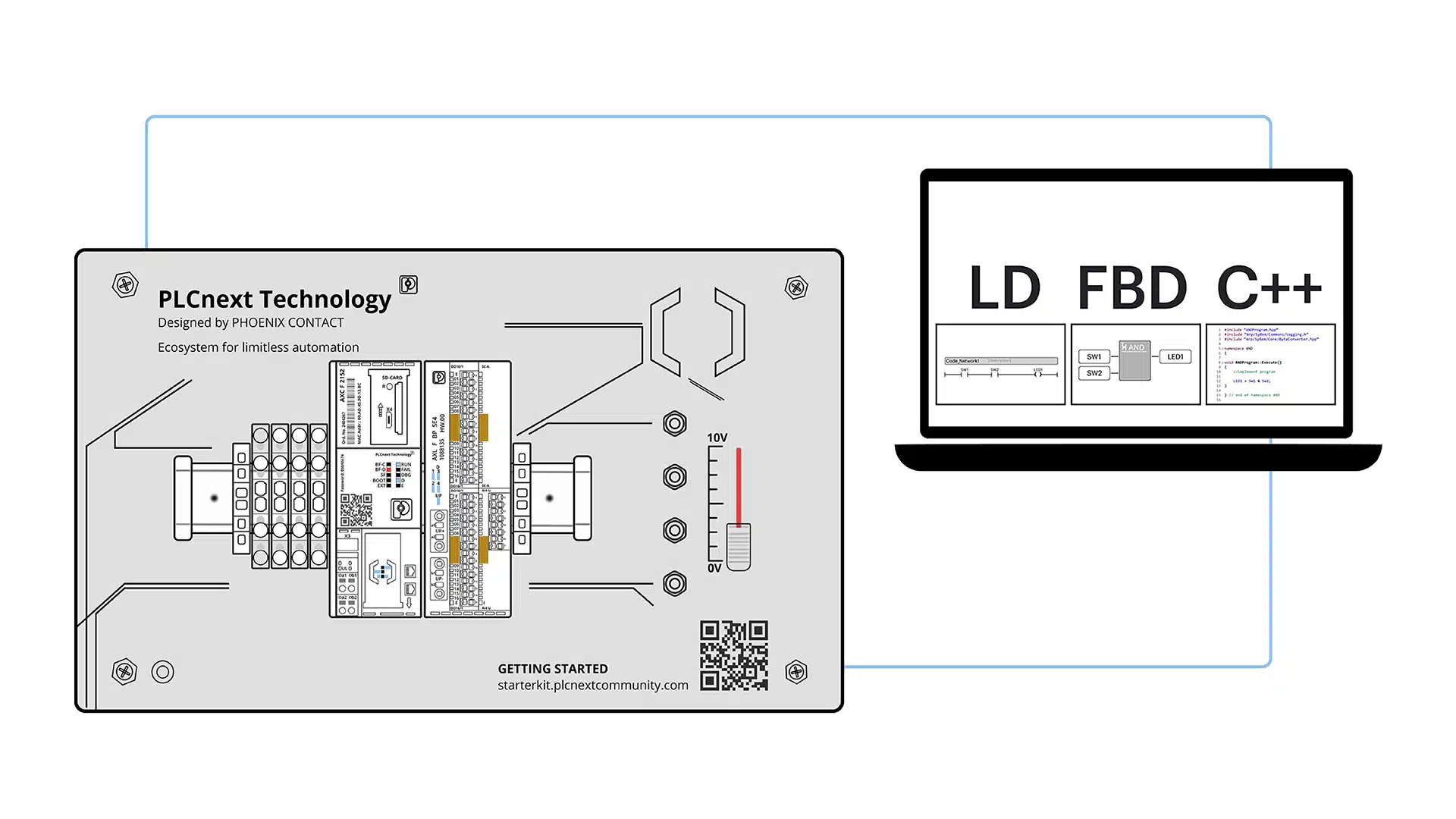
In this article, we’re going to use three different PLC programming languages to solve one problem. We’re going to use two IEC 61131-3 languages and a higher-level language called C++.
We’ll use PLCnext Engineer to facilitate our coding and we will run our programs utilizing the hardware and I/O on the PLCnext Starterkit.
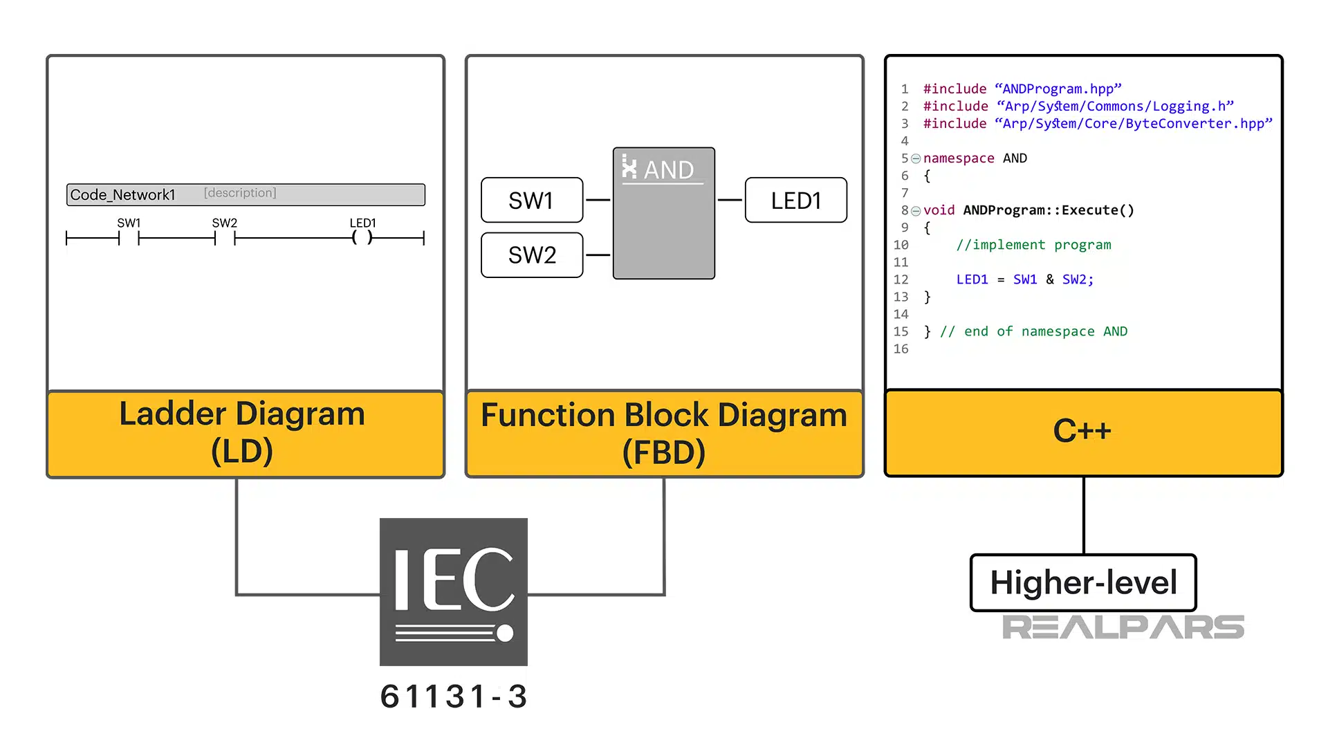
The IEC 61131’s five programming languages specified in the IEC 61131-3 Standard are Ladder Diagram, Instruction List, Function Block Diagram, Structured Text, and Sequential Function Chart. We are going to use Ladder Diagram and Function block in our exercise.
PLC programming
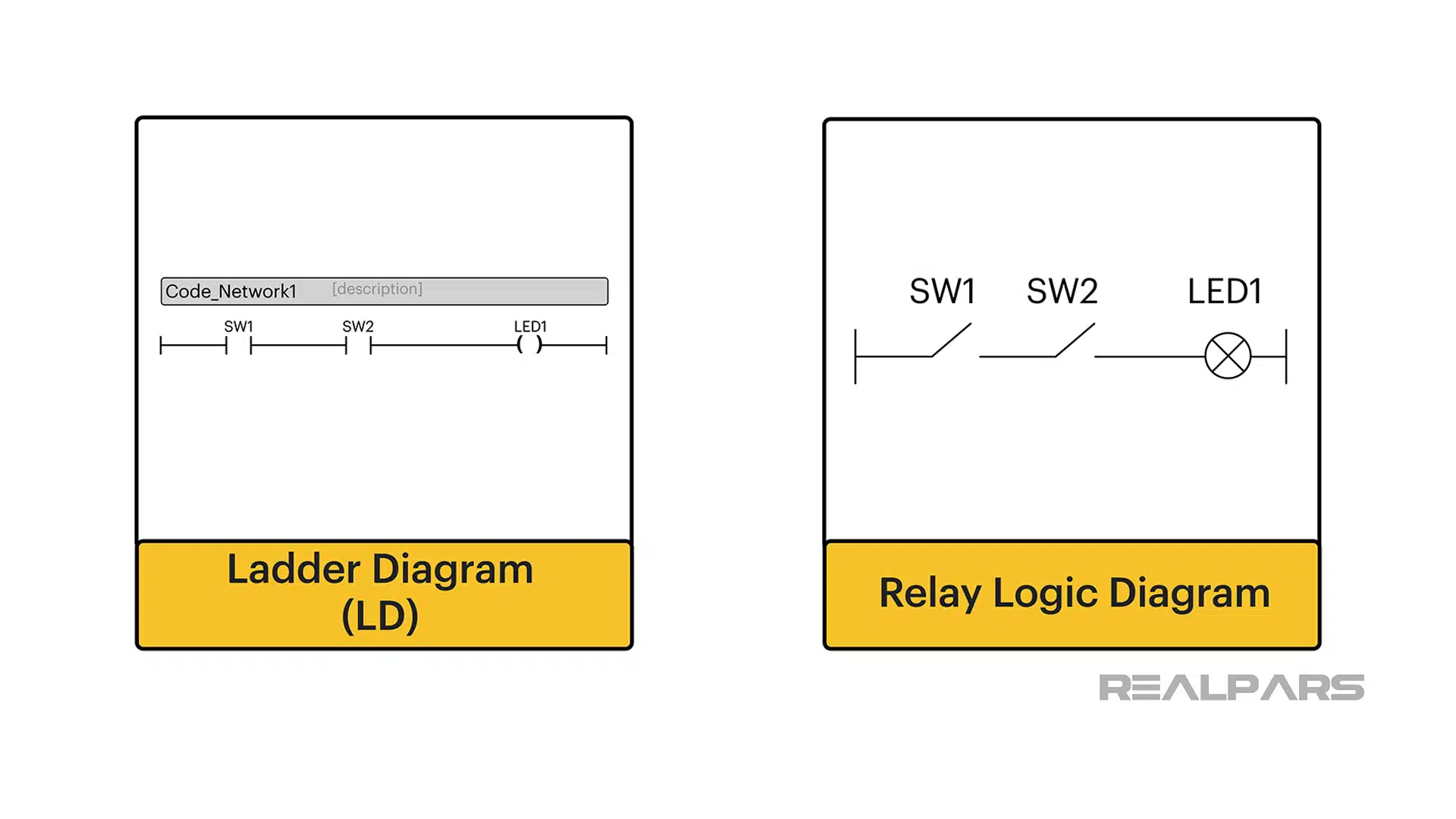
Ladder Diagram was the first language developed for PLC programming. The simple explanation for why Ladder Diagram programming became so popular was that it closely resembled traditional Relay Logic Diagrams.
Electricians and Engineers alike were familiar and comfortable with Relay Logic Diagrams and easily adapted to Ladder Diagrams.
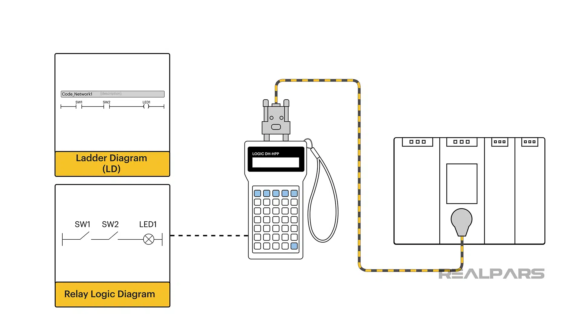
Early Ladder Diagram programming involved entering typical relay-type symbols onto a rung via hand-held programming devices connected to a PLC. It wasn’t long before computers and Graphical User Interfaces made this process much easier.
This was all well and fine until more complex PLC hardware and I/O were developed and programming languages needed to advance thus spawning Function Block and other languages.
Now we are at a point in history where there is an overlap between the activities of IT programmers and PLC programmers.
More complex functions are not easily accomplished with traditional IEC 61131-3 languages and require higher-level languages such as C++ which is a familiar language in the world of IT programmers.
For example, C++ programs can be easily created to produce logged data to assist with Predictive Maintenance (PdM). A program of that complexity cannot be easily created using Ladder Diagram.
Ok… We’re ready to start programming. Let’s begin with our problem. We want an LED to turn on when two normally-open pushbutton switches are operated.
Our Starterkit has pushbutton switches hard-wired to the inputs of the digital input module. We’ll use one of the LED indicators on the digital output module.
Ladder Diagram programming
We’ll use Ladder diagram programming first. Our ladder diagram has two open contacts operated by SW1 and SW2 on the PLCnext Starterkit.
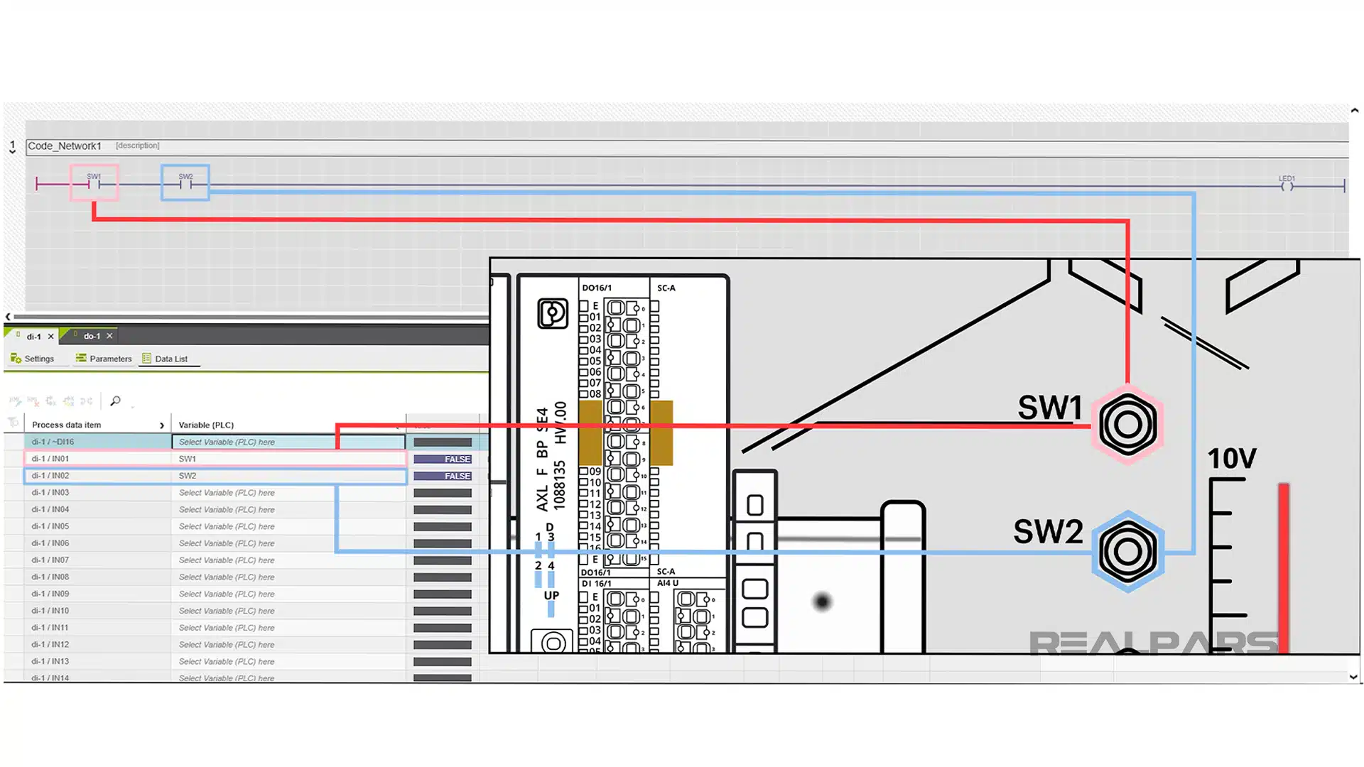
Operating the coil output will turn on LED1 on the digital output module.
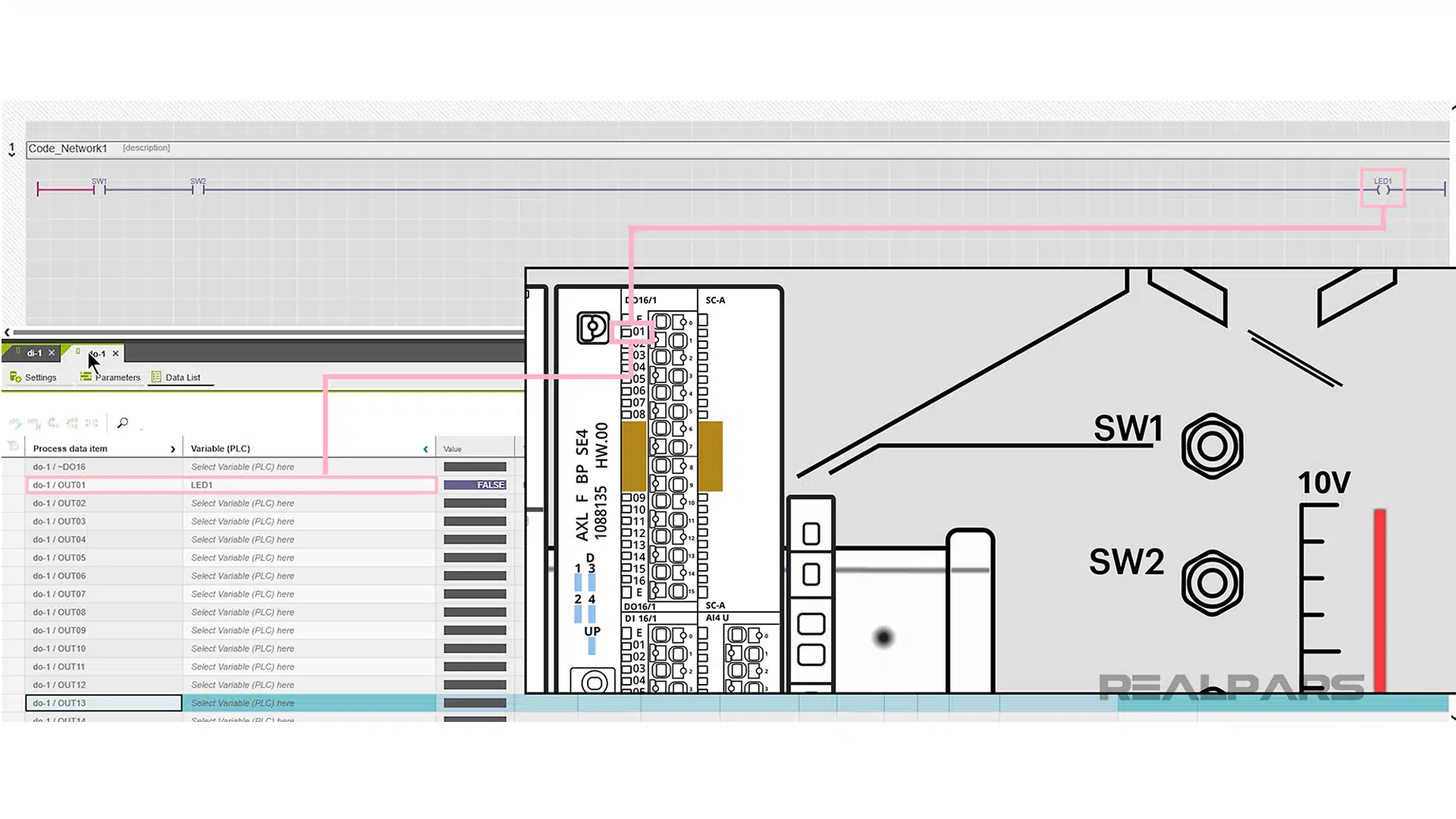
Operating SW1 and SW2 switches on the Starterkit simultaneously will close both normally open contacts, energize the coil symbol and cause LED1 to turn on.
Function Block programming
Ok… let’s solve the problem using Function Block programming.
Unlike Ladder Diagram, Function Block Diagram or FBD does not resemble any relay logic diagram or electrical circuitry of any kind. Basic blocks of FBD are based on Logic Operators such as AND, OR, and NOT.
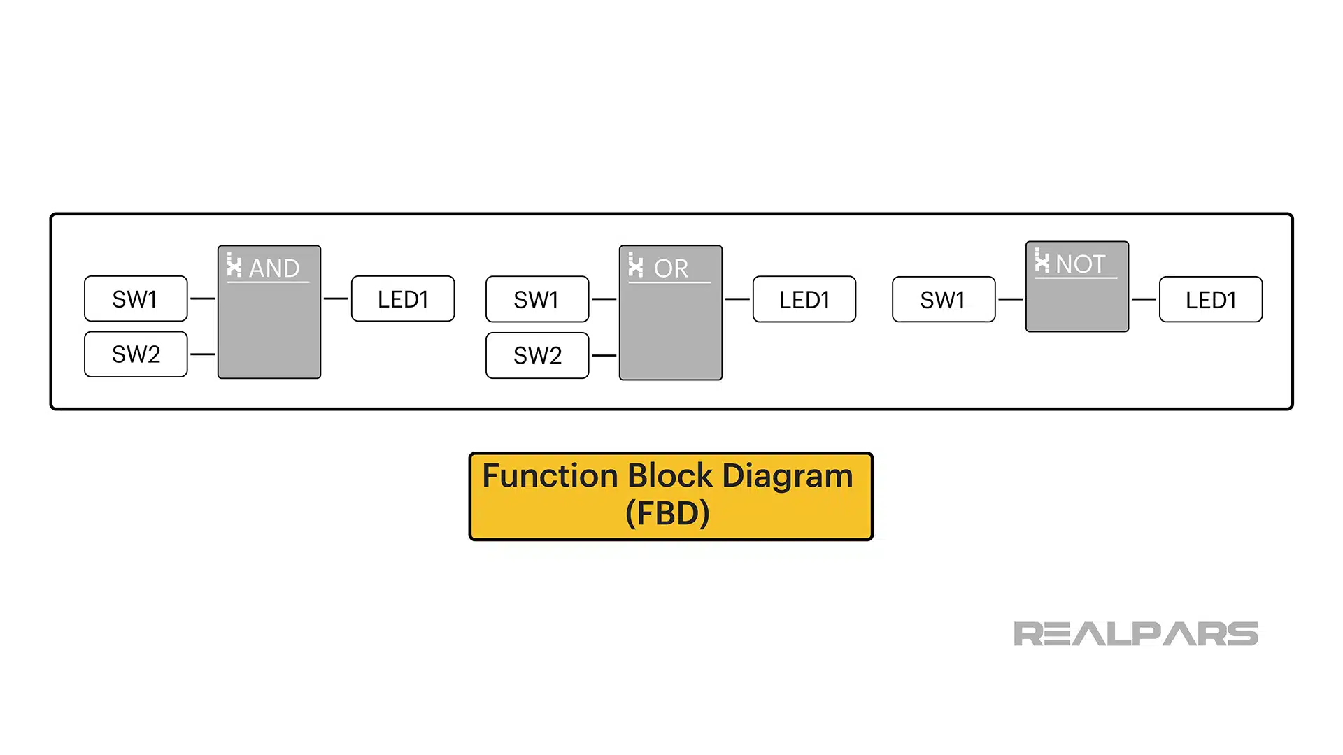
Thinking back to our problem, we want LED1 to turn on when two normally-open pushbutton switches called SW1 and SW2 are operated. The key word in that sentence is the logical operator AND.
If we express our problem in a slightly different way, we get: SW1 AND SW2 = LED1
So, our FBD to solve our problem is built around an AND Function Block.
As you may have guessed, operating SW1 and SW2 switches on the Starterkit simultaneously will cause the AND Function Block SW1 and SW2 inputs to go TRUE.
This action will cause the AND Function Block LED1 output to go TRUE and the LED1 on the output module will turn on.
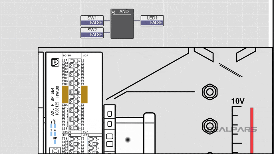
So, physically there’s no difference in operation between the LD program and the FB program.
Of course, there are Function Blocks for other logical operators such as NOT and OR.
C++ programming
Alright… let’s move on to C++ programming.
We used Eclipse IDE as our C++ Editor. There are many other possible choices available. Because C++ is not an IEC 61131-3 language, it is not a programming choice available in PLCnext Engineer.
With a few simple tools, a C++ project created in Eclipse can be imported into a PLCnext Engineer project.
We have to create INPUT and OUTPUT ports in the C++ project allowing us to connect to the Starterkit I/O via PLCnext Engineer.
We create INPUT ports for SW1 and SW2 and an OUTPUT port for LED1.
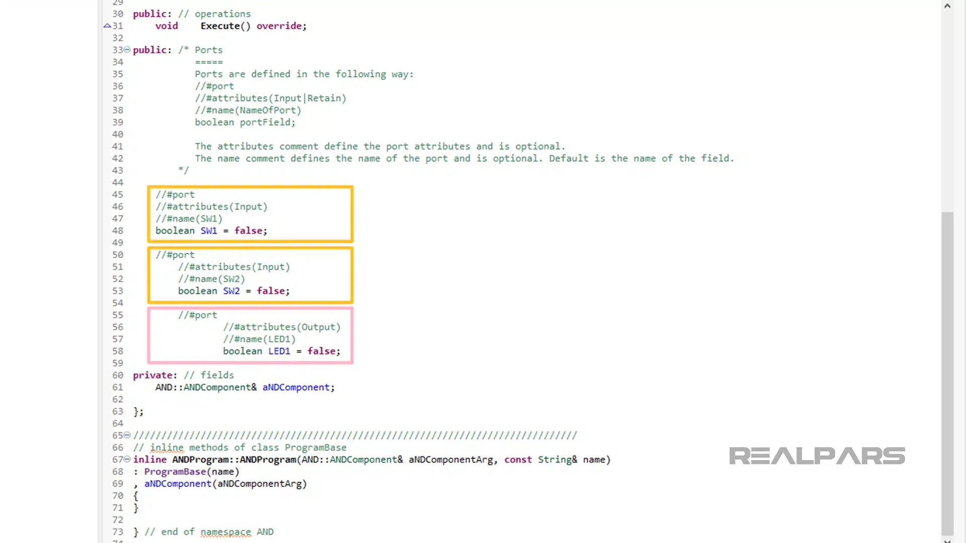
Then, we write the actual C++ program.
The ampersand, &, symbol is the logical Operator AND in C++.
So, the expression LED1 = SW1 & SW2 is almost exactly the same as the FBD expression, LED1 = SW1 AND SW2.
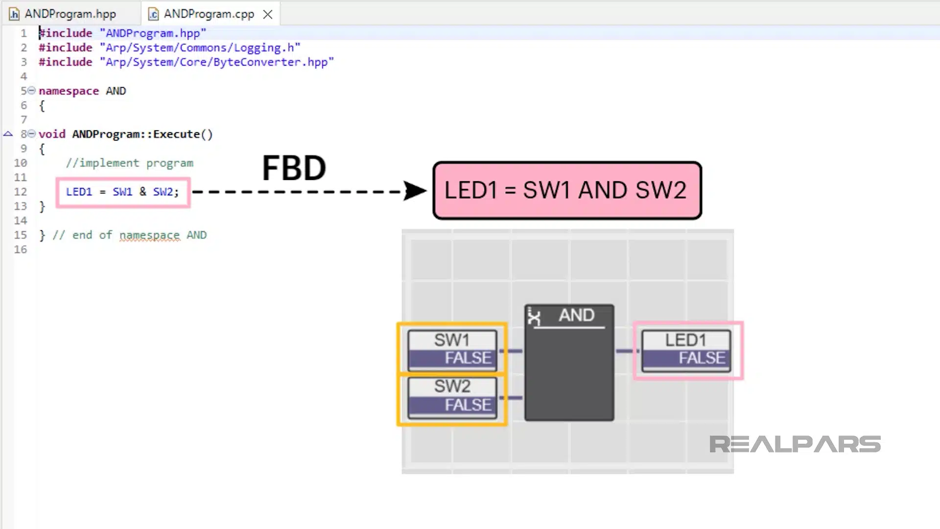
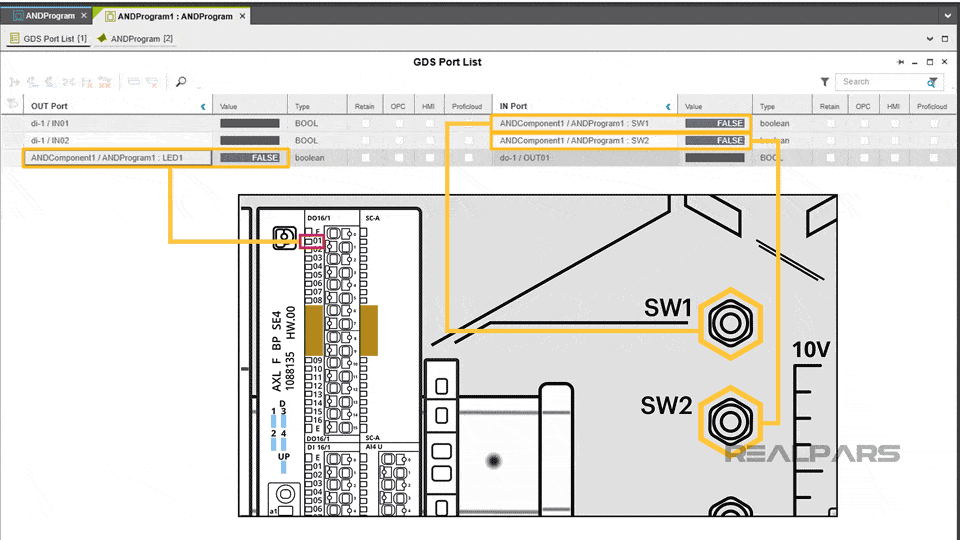
The coded C++ Project is added to the Library in PLCnext Engineer and the program is added to the Main Task. The program takes on a much different look once inside PLCnext Engineer.
Last but not least, the ports are assigned to their respective I/O devices on the Starterkit. And we’re ready to download and run our C++ program.
We begin with Starterkit SW1 and SW2 switches not operated therefore SW1 and SW2 are FALSE. LED1 will be OFF on the output module and LED1 in the program is FALSE.
Operating the SW1 and SW2 switches on the Starterkit simultaneously will cause the IN Port SW1 and SW2 to go TRUE. This action will cause the OUT Port LED1 to go TRUE which will turn on LED1 on the output module.
Comparison of the three programming languages
So, physically there’s no difference in operation between any of the three programs we used to solve our problem.
The obvious question is What programming language should you use?
There’s really no single correct answer as there isn’t one best PLC programming language.
It’s apparent that we wouldn’t use C++ to solve the simple problem presented in this exercise as Ladder Diagram or Function Block are easier and more appropriate.
Each language has its strengths and weaknesses and degrees of suitability for specific applications and of course, the challenge is to choose the correct one.
Want to learn more?
If you’re just starting out in the world of PLC programming, you can upgrade your skillset with a free course on PLCnext from RealPars!
Starting with the basics and working up to programming in ladder logic or C++, you’ll have a handle on this exciting new technology when it’s all said and done.
Phoenix Contact even supplies an official certificate of completion after completing each pro course.