

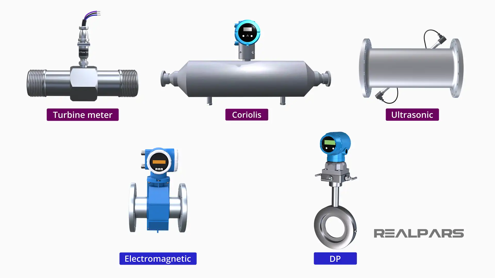
There are many types of process flow meters. Coriolis mass flow meters; positive displacement flow meters, such as turbine meters; and volumetric flow meters, like ultrasonic flow meters, just to name a few.
In fact, there are at least eighteen different types of flow meters. Why are there so many different types, you may ask? Each type of flow meter operates on different physical, mechanical, and electrical principles.
In this article, I will explore the working principles for Ultrasonic flow meters. I will demonstrate how a simple physical property, sound, can be used to measure the rate of flow of a fluid moving in a pipe.
What is an ultrasonic flow meter?
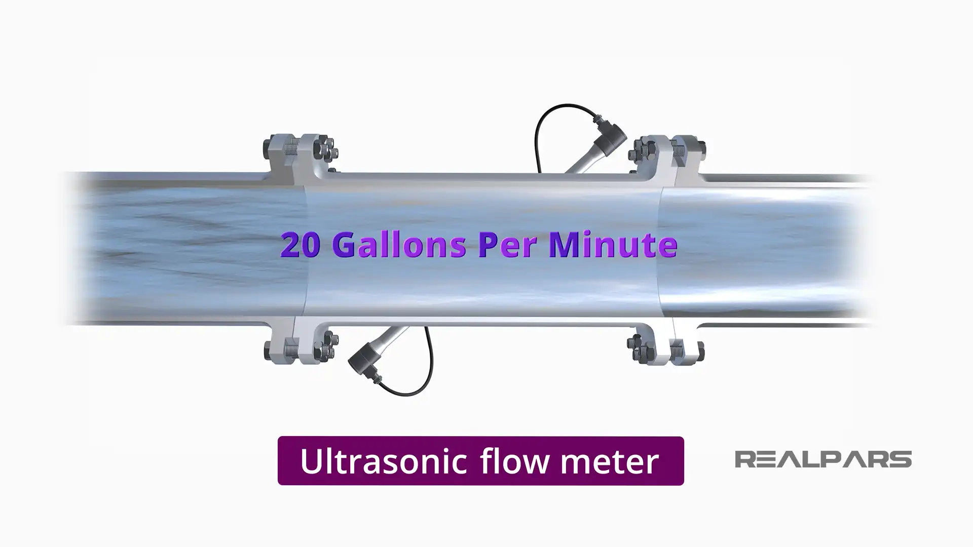
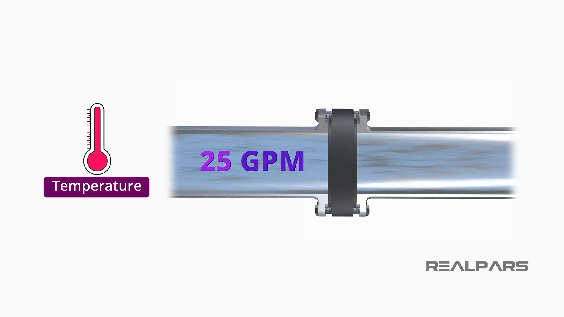
Ultrasonic flow meters measure the volumetric flow of the fluid, that is, the number of gallons or liters per unit time, such as minutes.
Basic principles of ultrasonic flow measurement
I will show that ultrasonic flow meters require the use and understanding of some basic physical, mechanical and electrical principles that allow ultrasonic flow meters to accurately measure flow rate over a wide range of flow conditions.
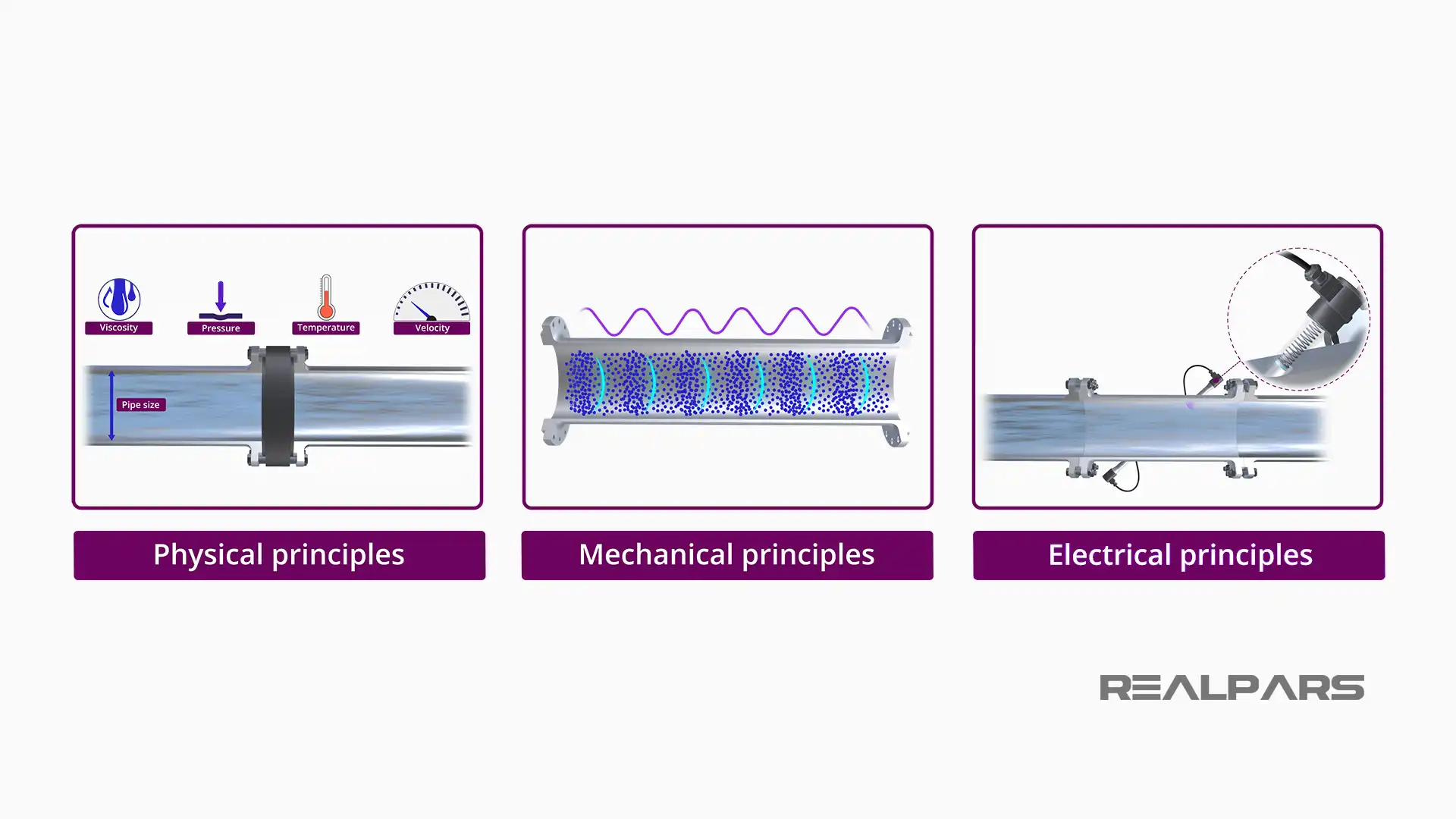
Physical principles
When fluid flows through a pipe, it flows in one direction at a velocity that is influenced by many factors, such as temperature, pressure, fluid viscosity, and pipe size.
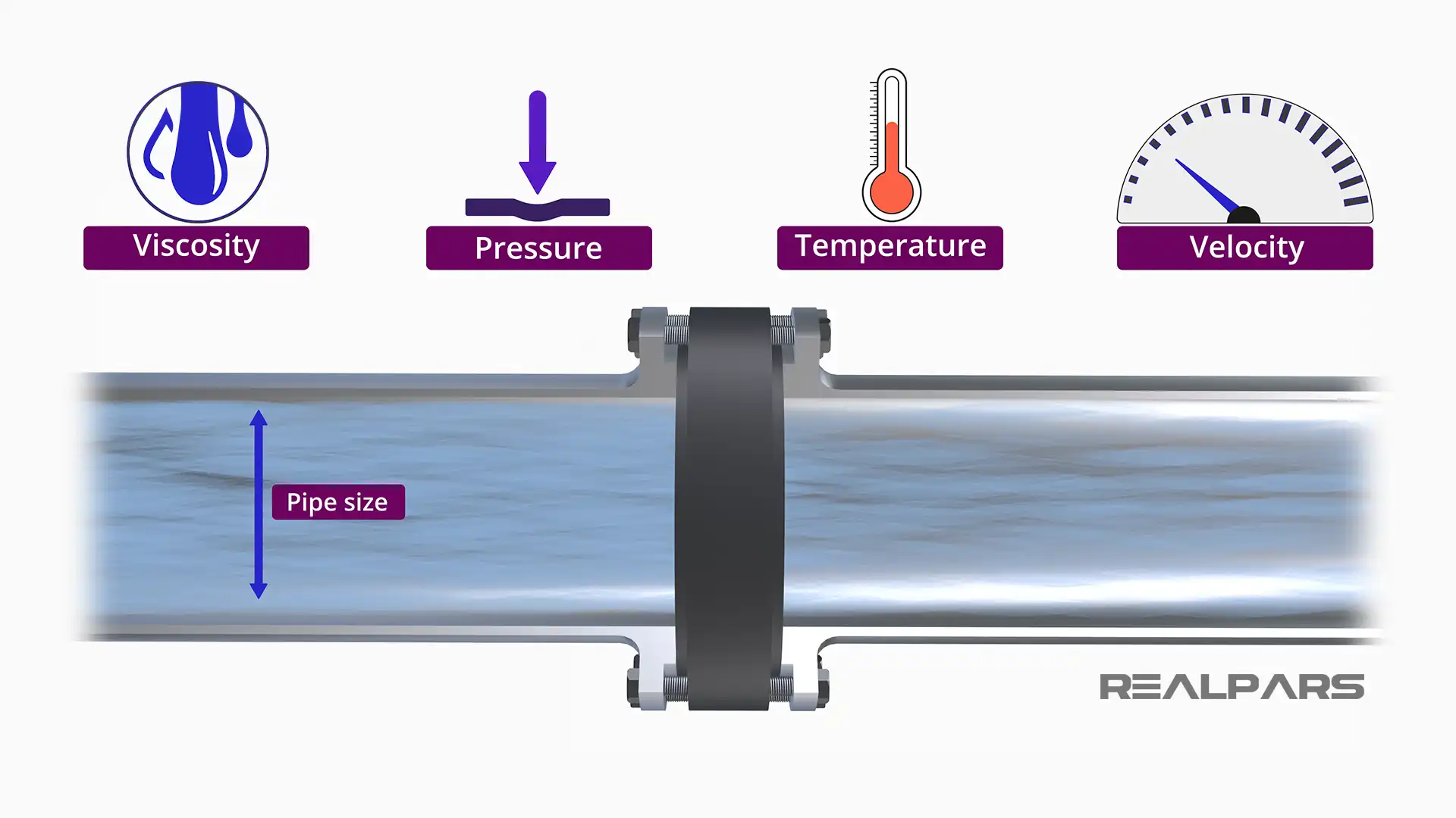
The higher the pressure differential upstream of a point in the pipe and downstream from that point, the higher the flow velocity.
Increasing the temperature usually leads to increased flow all other factors remaining the same.
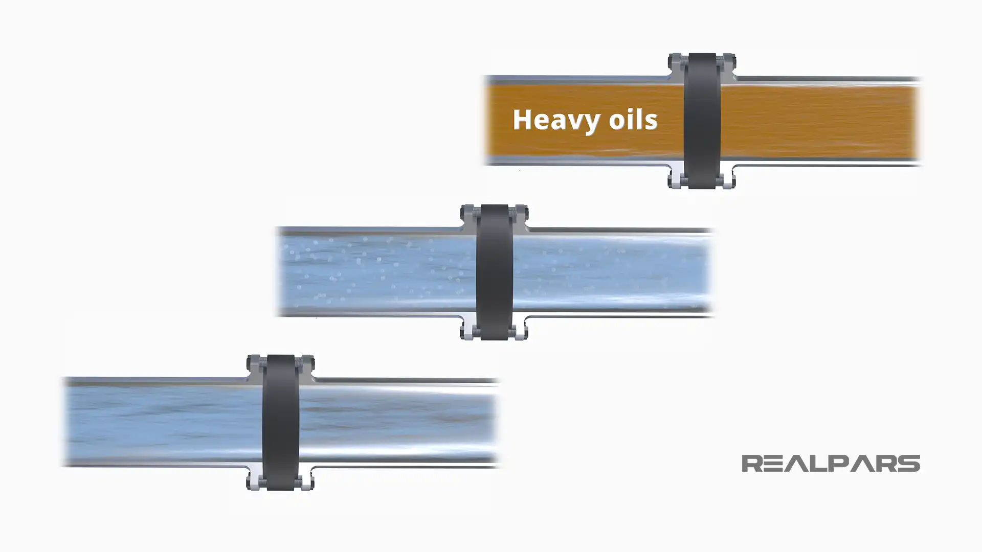
Some fluids are clear; some contained particles or bubbles. Some fluids are very viscous, like heavy oils, and do not flow as easily as less viscous fluids, like water.
Mechanical principles
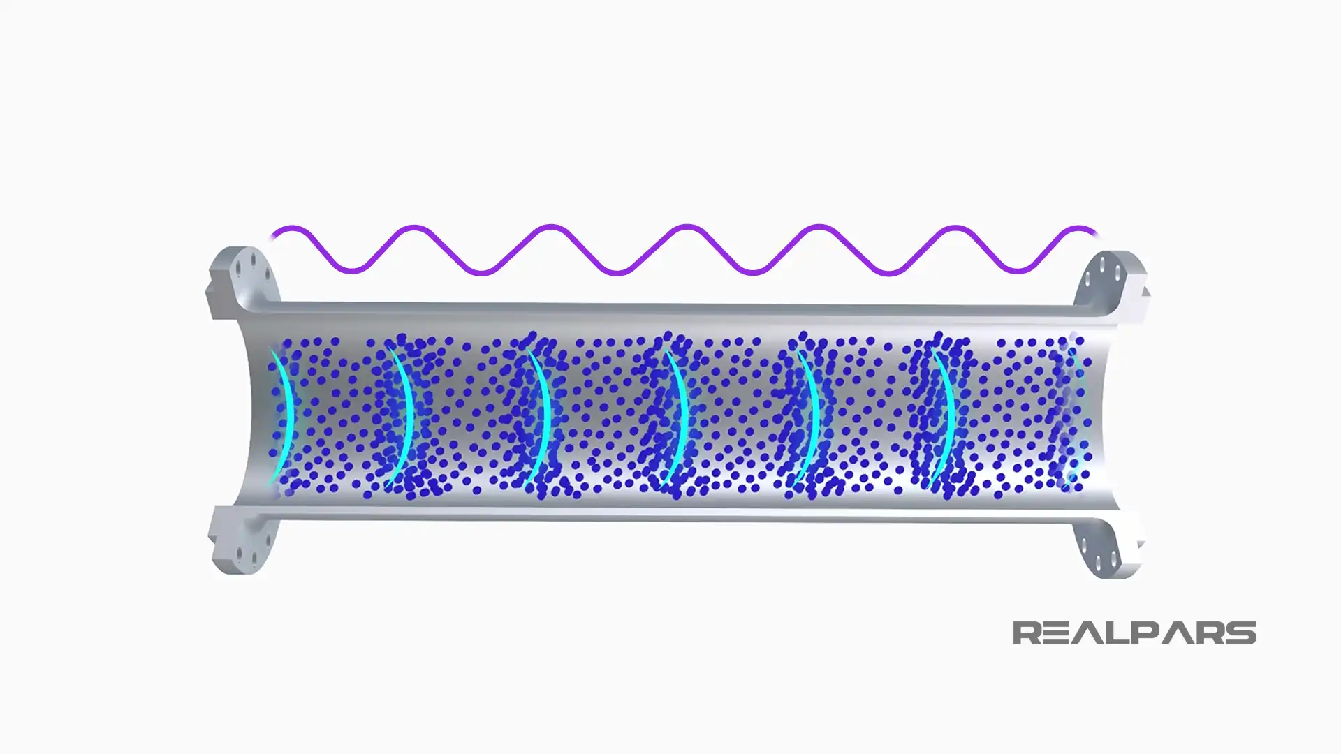
Sound waves move through a fluid based on the transmission of vibrations through the fluid. These mechanical oscillations between molecules of the flowing fluid are passed to adjacent molecules, thereby transferring the wave to those adjacent molecules.
A car horn is heard because a rapidly vibrating diaphragm transmits high-frequency waves through the air, the fluid of transmission, in this case.
We are able to hear the sound because the vibration frequency is in the audible range, about 20 hertz to 20,000 hertz.
Ultrasonic flow meters operating at frequencies of vibration are outside of the audible range, at 25 kilohertz or above. These higher frequencies allow more accurate measurement as well as not generating sounds in the audible range.
Electrical principles
How does an ultrasonic flow meter generate these sound waves? The answer is a rapidly vibrating piezoelectric crystal. These special ceramic crystals deform when an electric current is applied.
By rapidly changing the electrical signal, the crystal will deform in one direction, and then in the other, causing a high-frequency wave to be generated.
Ultrasonic flow meter dynamics
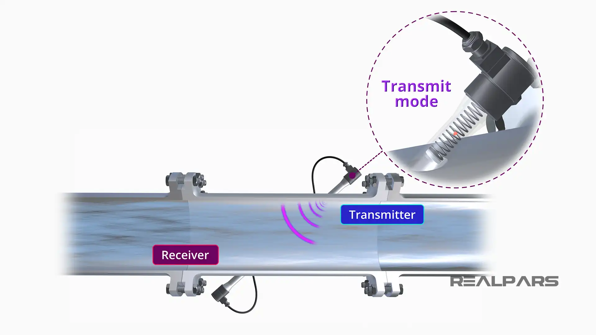
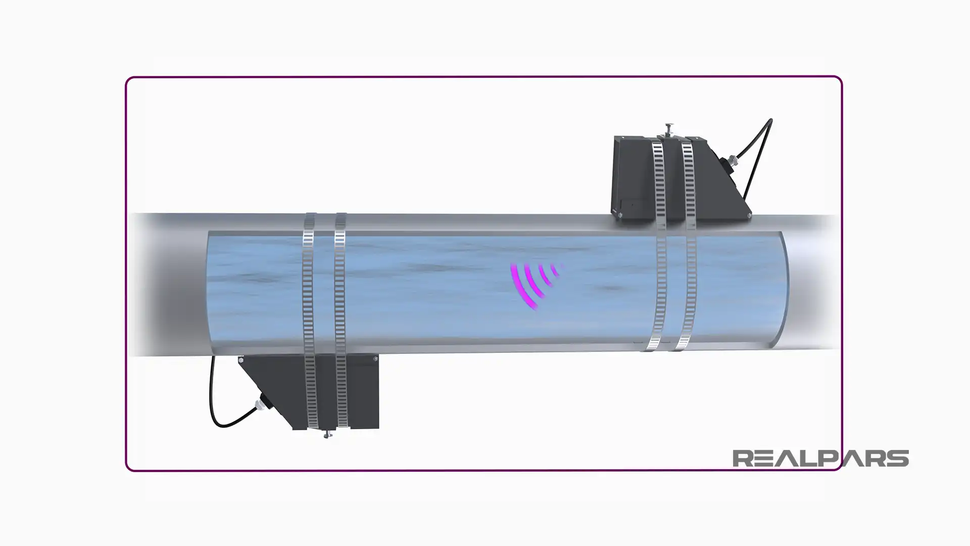
So, I will put these three principles together. An ultrasonic flow meter consists of at least one sensor and transducer pair. Each member of the pair can act both as a transmitter and a receiver.
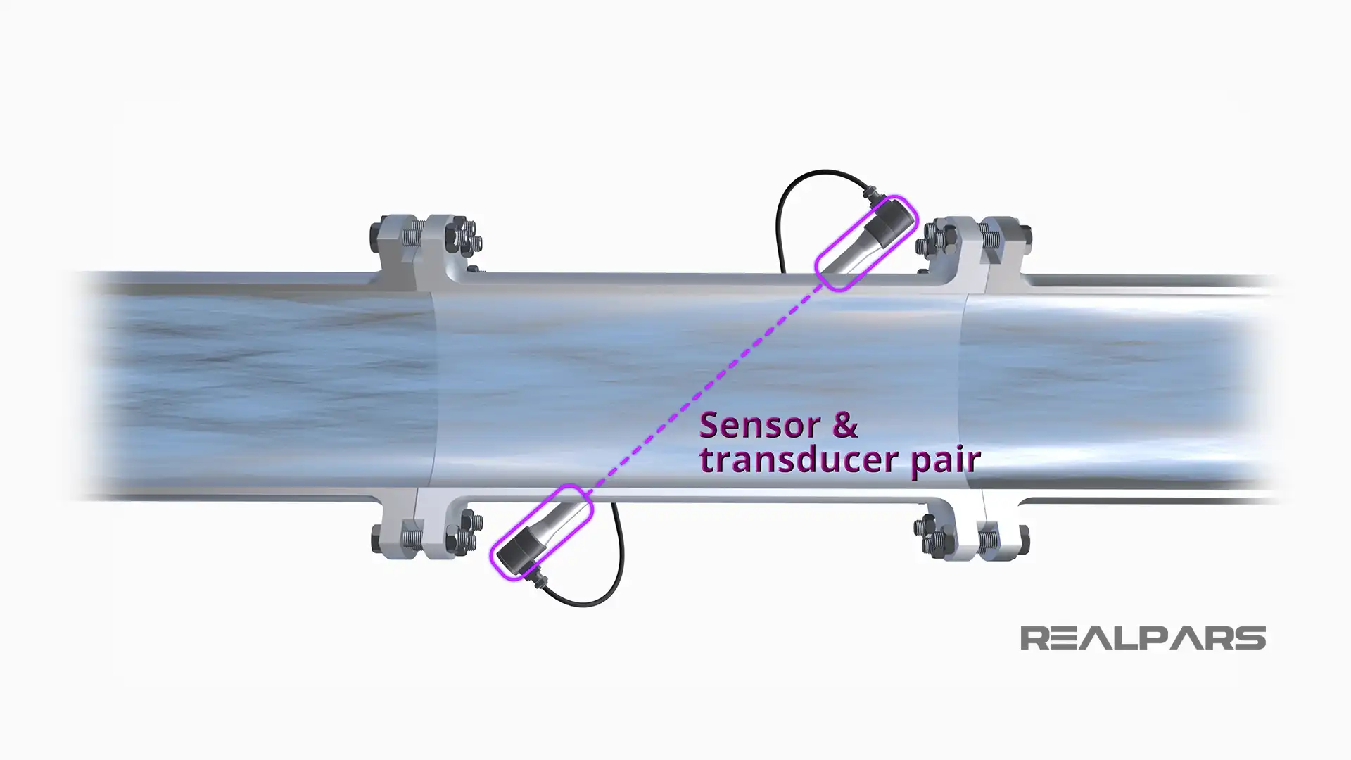
When in transmit mode, an oscillating electrical current creates a vibration in the piezoelectric crystal, and an ultrasonic wave is sent through the flowing fluid.
When in receive mode, an ultrasonic wave passing through the fluid creates vibration in the piezoelectric crystal, and an electrical impulse is generated.
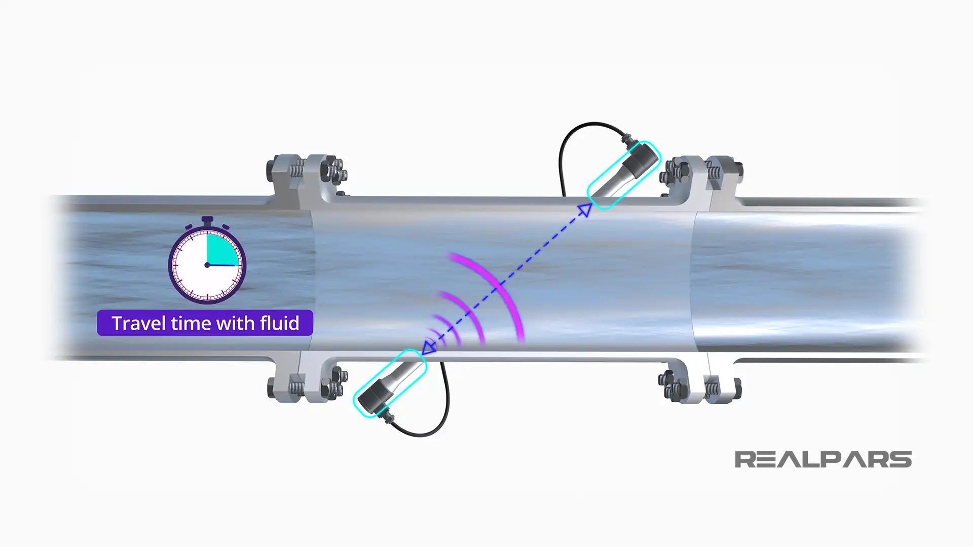
The time it takes for the ultrasonic wave to pass from the transmitting element to the receiving element depends on several factors. If the two elements are placed at slightly different locations along the pipe, then the fluid velocity will affect the time it takes for the signal to reach the receiving element.
In a stagnant fluid, the vibration is passed from the transmitter to the receiver in a measurable amount of time. The ultrasonic pulse generated in the opposite direction should take the same amount of time. The measurement environment is constant.
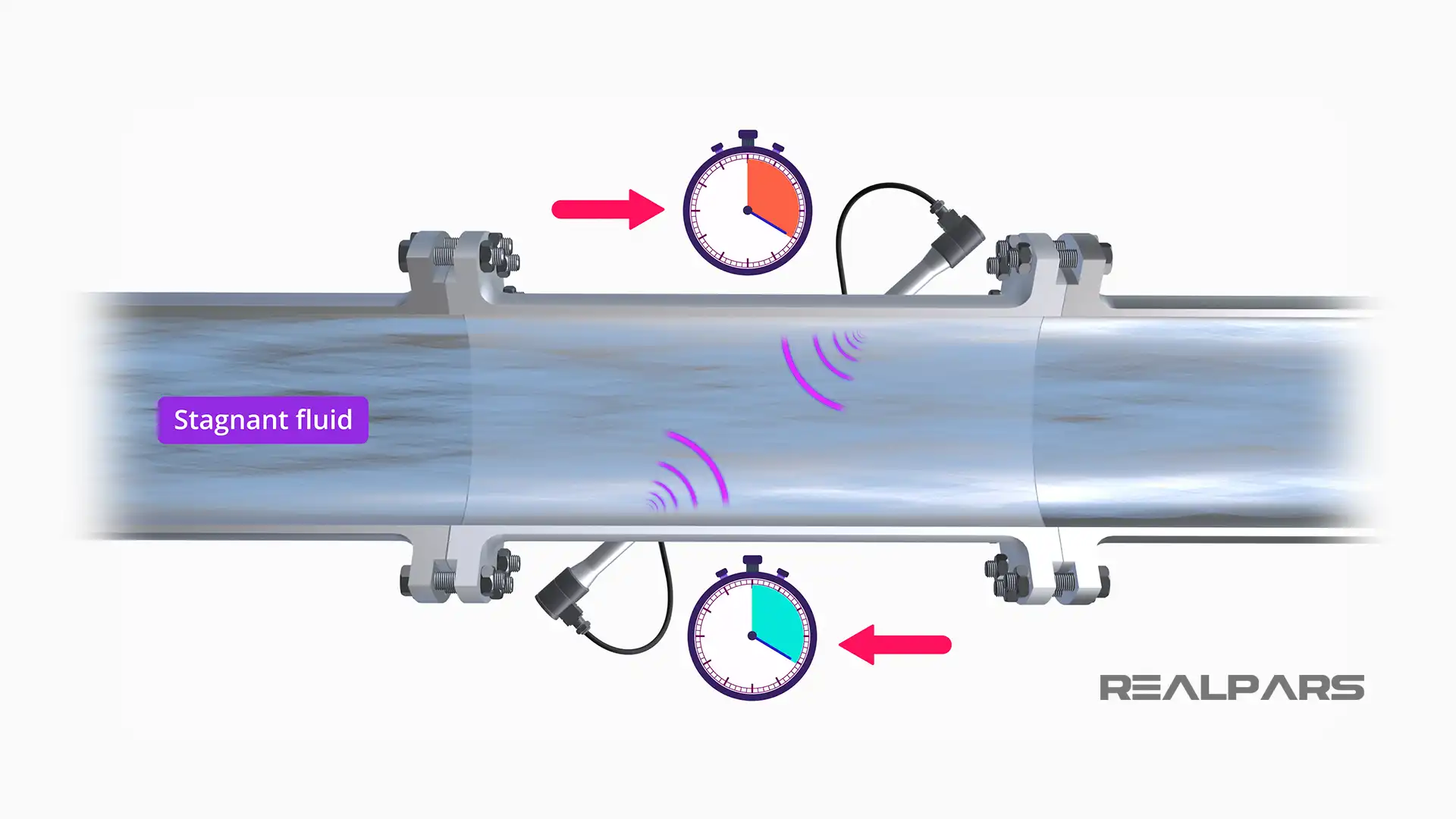
However, since ultrasonic waves have mechanical properties, the time it takes to move from transmitter to receiver is affected by the fluid velocity.
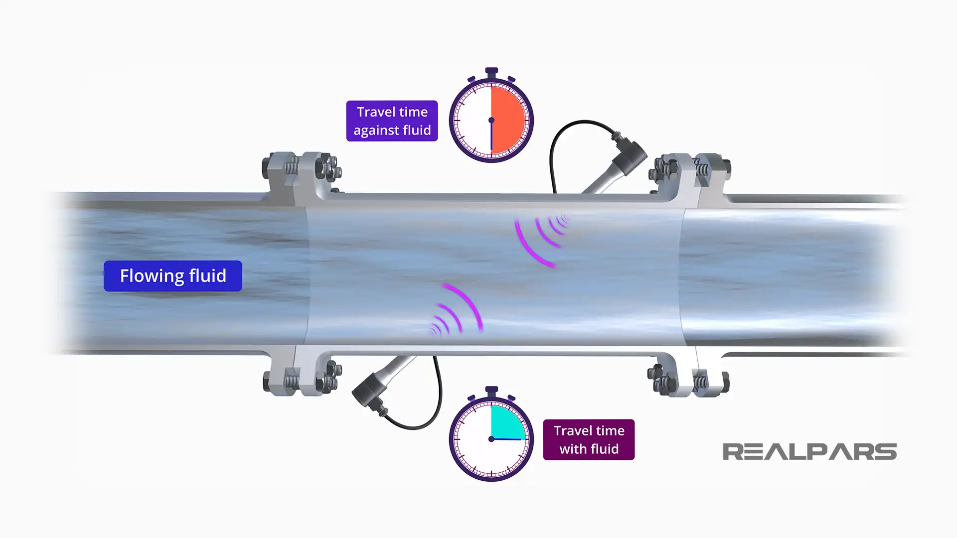
A pulse that travels from the upstream element to the downstream element, or with the flow, takes less time to make the trip than the pulse returning in the opposite direction, or against the flow.
Think of this as the time it takes to swim between two points going with the flow and against the flow.
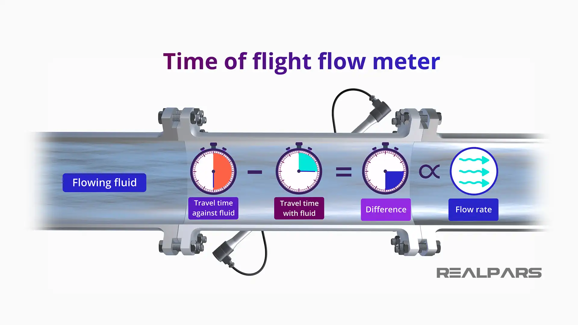
The difference in this time of flight between the two pulses is directly proportional to the flow velocity. Since the volumetric flow rate is equal to velocity times the cross-sectional area of the pipe, which is fixed at the flow meter, this measurement yields the flow rate. This type of ultrasonic flow meter is appropriately named a “time of flight” flow meter.
Ultrasonic flow meter design considerations
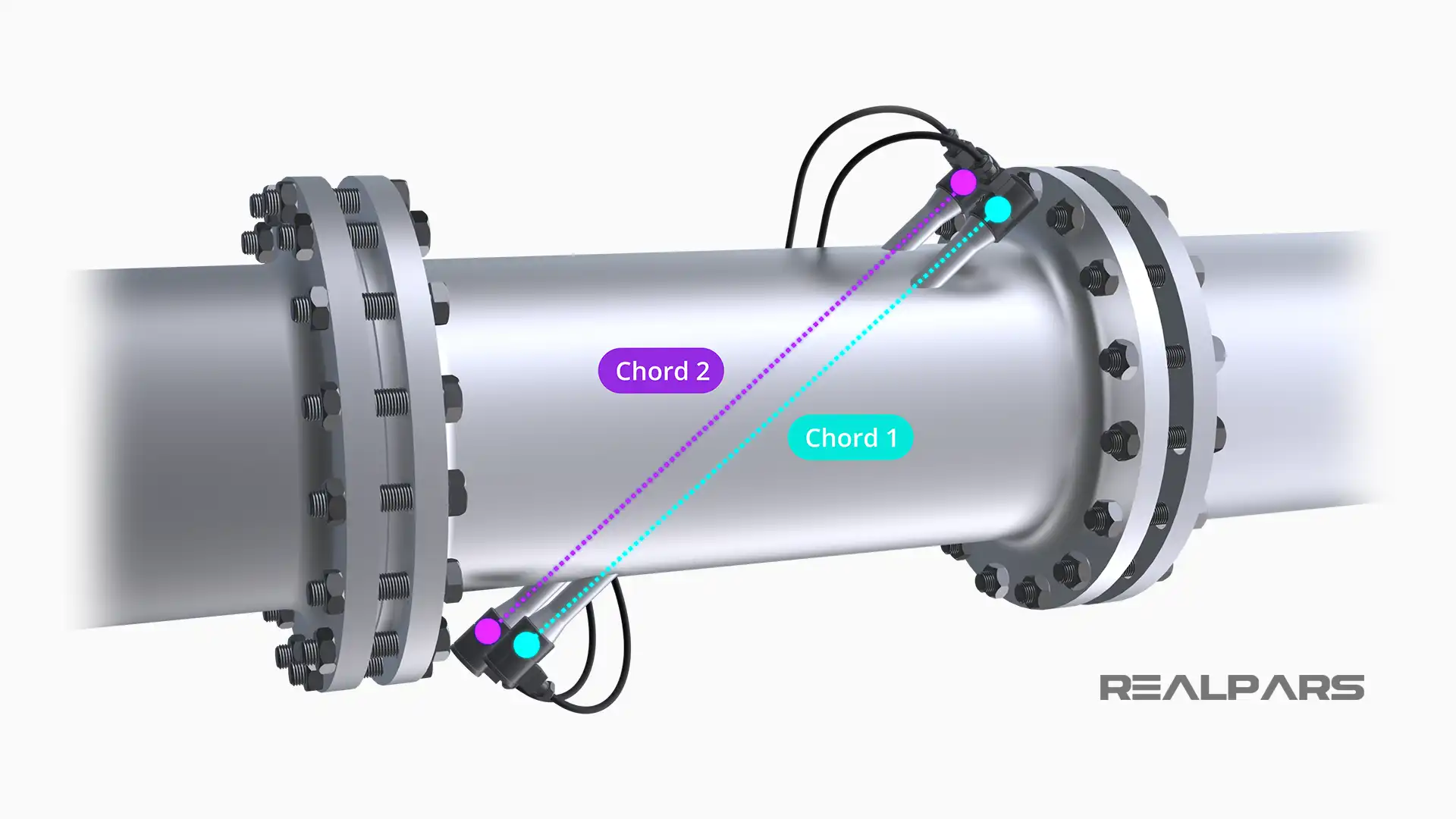
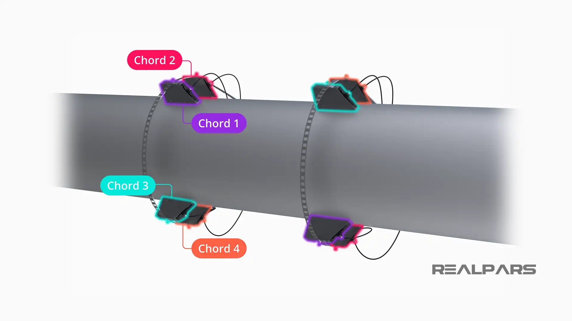
In order to eliminate differences in the flow profile across the pipe, additional pairs of sensors are added to ensure an accurate measurement.
Each pair of transmitter and receiver forms what is called a chord. Each chord is placed to provide measurement at a different location along the pipe circumference.
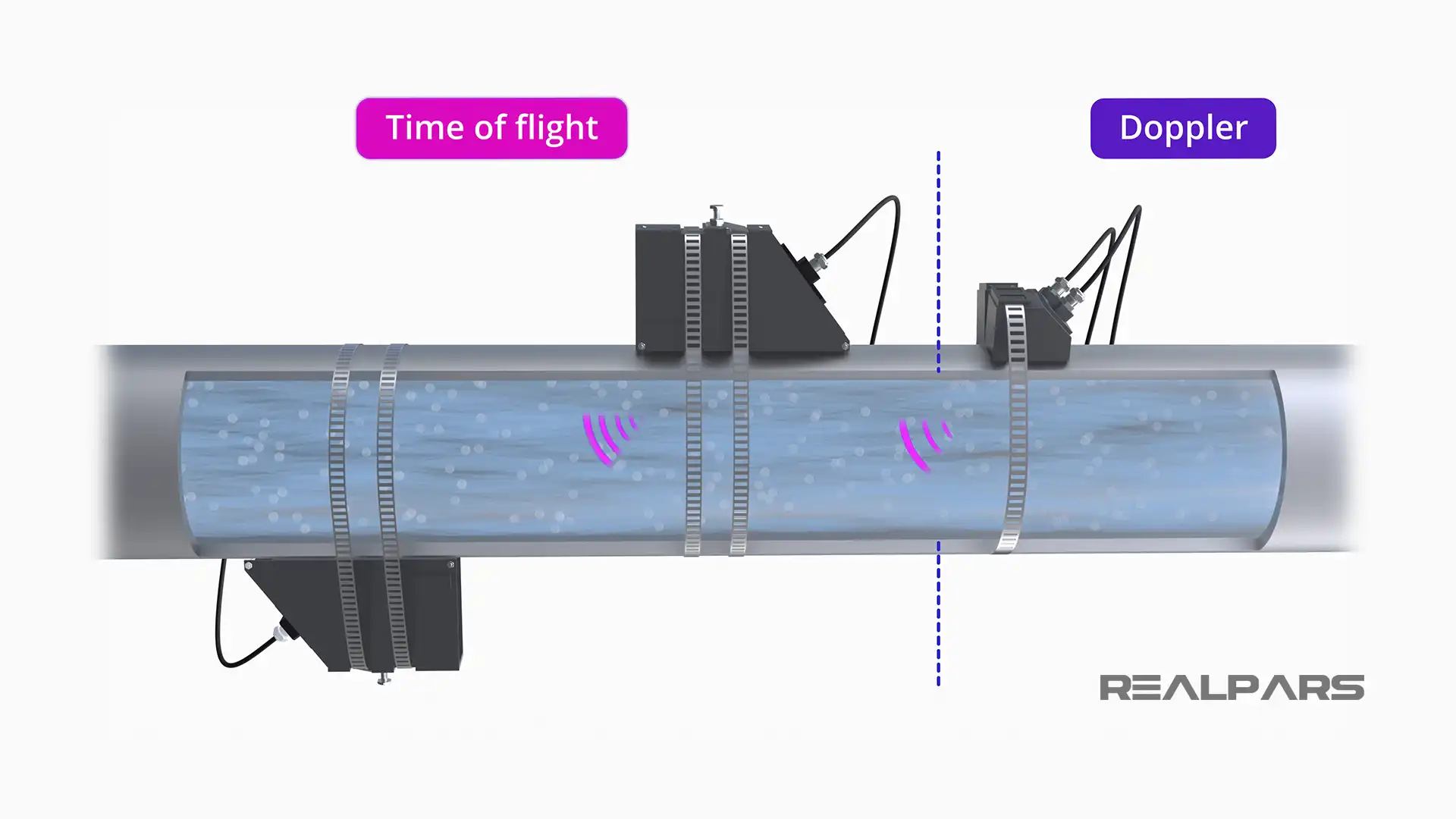
There are many different ways that the sensors are mounted in a time of flight ultrasonic flow meter. The sound wave pulses can travel directly from transmitter to receiver or the pipe wall can be used to reflect the sound waves.
The sensors can be wetted, or built into the wall of the flow meter such that the sensors contact the fluid. Or the sensors can be strapped to the exterior of the pipe, where the sensors do not contact the fluid.
The non-contact sensors are not quite as accurate, since the sound wave must travel through the pipe wall and the fluid, where the pipe wall may absorb some of the pulsed signals.
Another type of ultrasonic flow meter uses the Doppler Effect to measure flow rate. In this method, air bubbles or entrained particles are used to reflect the sound waves from the transmitter to the receiver.
As with the falling pitch or frequency of a train whistle as the train moves away from the observer, the shift in frequency observed at the receiver can be used to determine the flow rate.
Where to use an ultrasonic flow meter
Now that I have demonstrated how an Ultrasonic flow meter operates, you may ask, where are these flow meters used? Ultrasonic flow meters are an excellent choice for high-pressure, high-flow applications like natural gas pipelines.
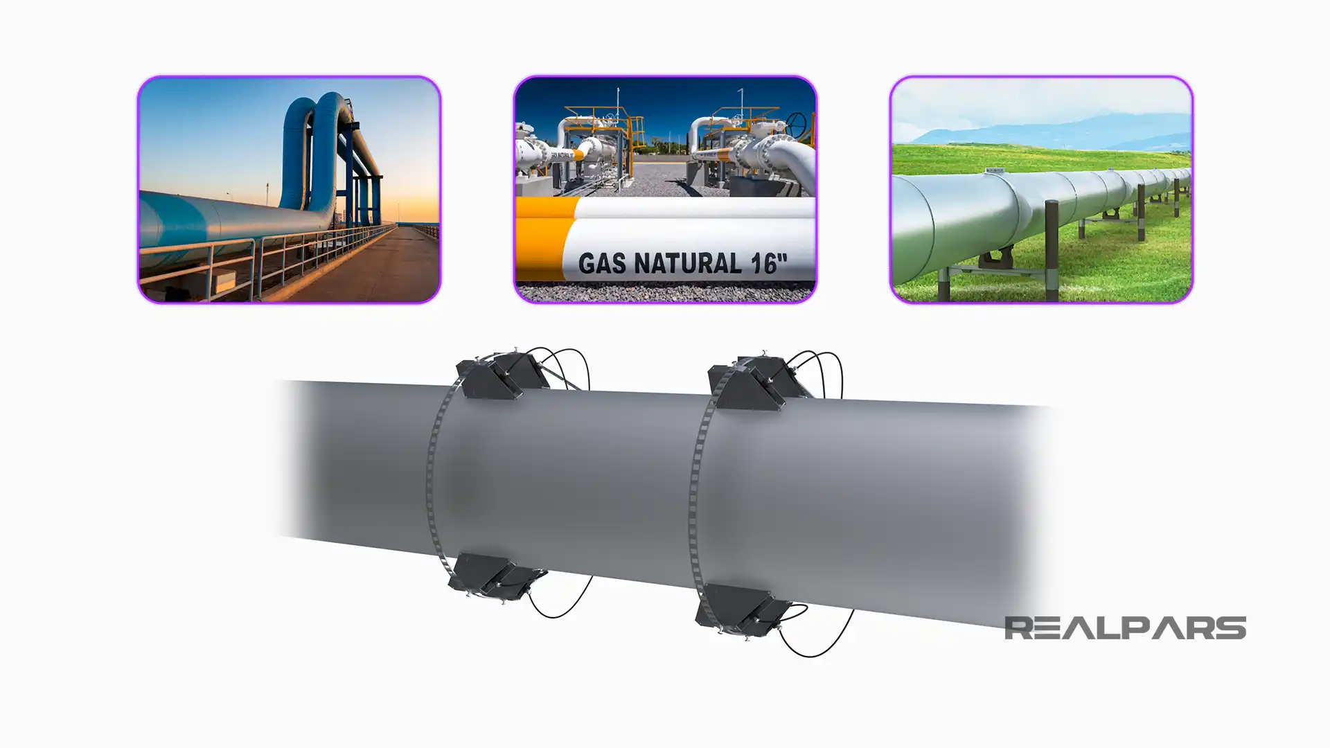
For these applications, time of flight meters are used with four or more chords for accuracy.
Municipal water and sewer systems often use externally mounted ultrasonic flow meters to measure flow because the penetration of the pipe is not required to install the flow meter.
Additionally, in some cases, time of flight and Doppler can be used in the same flow meter design to handle fluids, which may change composition over time. When particles or sediment is detected, the meter can change from Time of Flight mode to Doppler mode to maintain flow measurement accuracy.
Summary and Conclusion
This video has provided an overview of the working principles of ultrasonic flow measurement. Ultrasonic flow meters are extremely versatile, and for some fluid streams, such as natural gas pipelines and metropolitan water system flows, ultrasonic is the best choice.