PLCnext Starterkit | What’s in the Box?

This is the first of a series of articles about the Phoenix Contact PLCnext Starterkit. If you are interested in a powerful but inexpensive PLC, you might want to consider the PLCnext Starterkit.
Here are a few reasons to help you decide to get one.
The programming software is free!
In addition to typical PLC programming languages such as ladder logic, function block diagram, and structured text, you can also use other PLC programming languages such as Python, C++, and Java amongst many others.
In this article, we’re going to identify all of the PLCnext Starterkit bits and pieces in the box that arrived at your door. We’re also going to familiarize you with everything in the box and discuss the purpose and function of each item.
Alright… let’s get started.
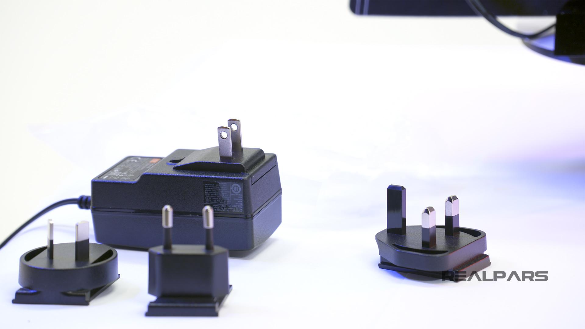
1) AC plug
The first thing you might notice is the 24 Volt power supply and a bag called AC plug-Mix.
All you need to do is pick out the AC plug that matches your wall receptacle and slide it into the open slot on the 24 Volt power supply.
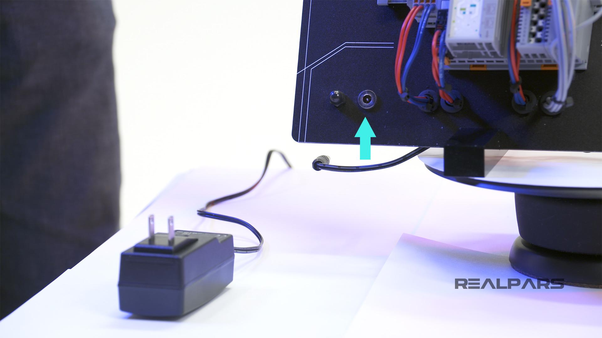
The output male plug of the power supply plugs into the female connector at the bottom left corner of the panel.
2) Ethernet cable
Next out of the box is the Ethernet cable.
The Ethernet cable is the communication link between your computer and the PLC. Don’t worry about Ethernet right now… we will be talking about communications in more detail in the next article, in this series.
3) PLC panel
Let’s have a look at the PLC panel itself.
There’s lots of stuff on this panel, so here we go… We will start by examining everything mounted on the DIN Rail.
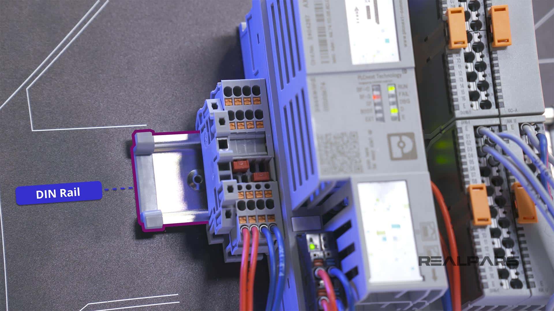
Terminal block
Mounted on the far left side of the DIN Rail is a PT 1,5 Quattro terminal block.
There are 4 actual terminal blocks on the DIN Rail.
A terminal block allows multiple outgoing wires to connect to one singular incoming wire.
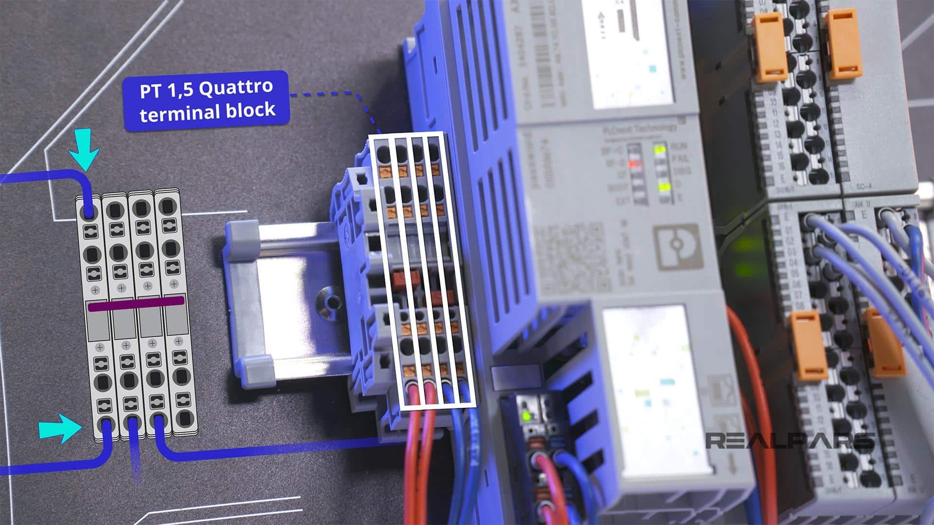
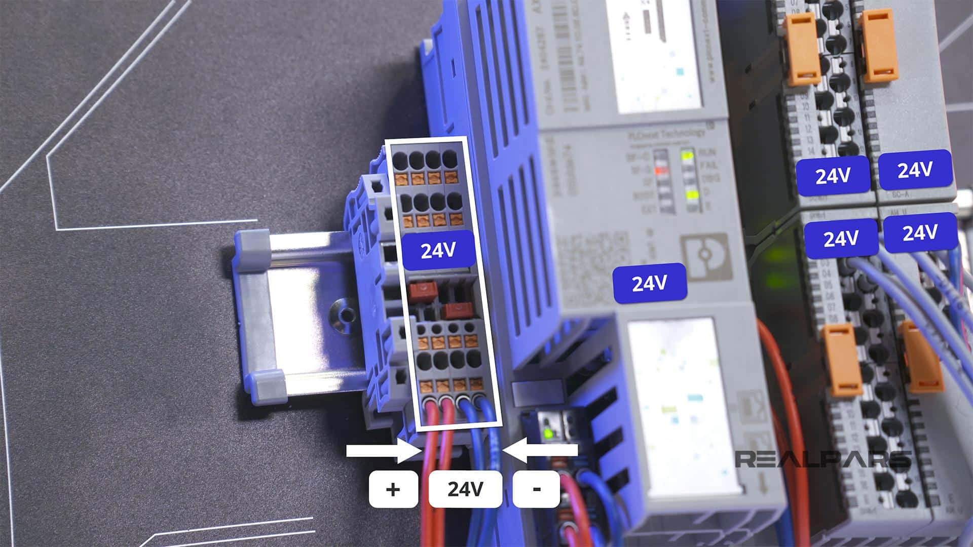
The Starterkit terminal blocks are currently used to distribute the 24 Volt power supply where needed on the panel. The red wire is the positive side of the 24 Volt supply and the blue wire is the negative side.
The terminal blocks are there for future use if you choose to use the power supply in your projects.
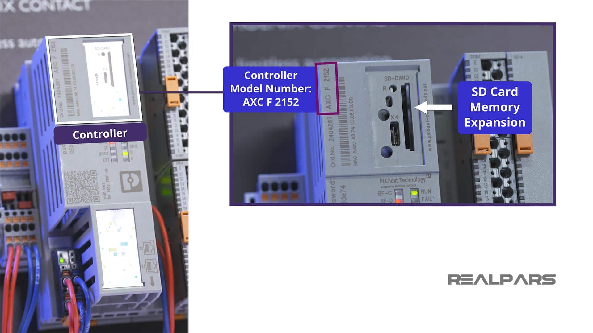
Controller AXC F 2152
Located beside the terminal block is the brain of the operation: the controller itself. The Controller Model Number is shown at the top.
If you need to order the AXC F 2152 controller separately for your projects, you can check out this link.
SD-CARD expansion slot
On the right-hand side, an SD-CARD Expansion slot is located under the plastic cover.
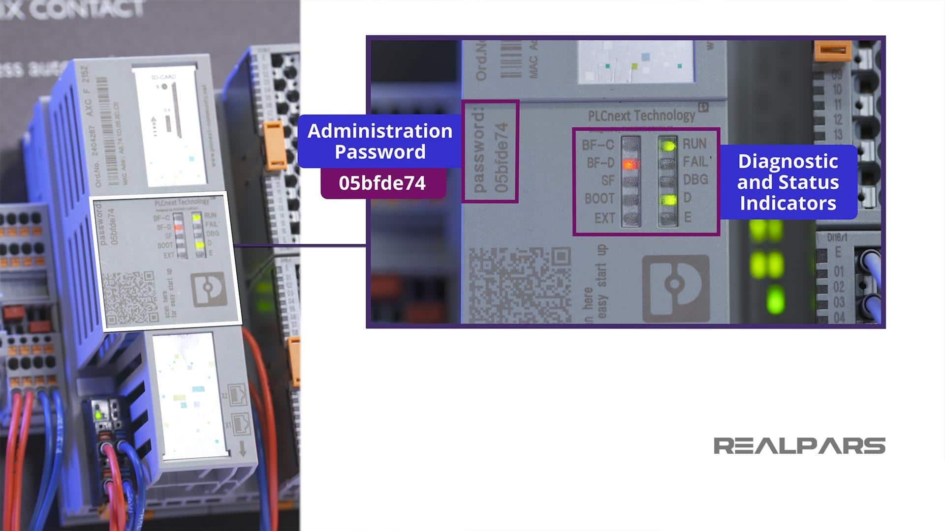
Administration password
A very important piece of information is shown next.
This is the Administration Password for your Controller. Be sure to note this password as you will need it in the next article of this series, How to Easily Create PLCnext Ladder Logic Programs.
LED’s indicator
There is a cluster of LED’s located in the middle of the controller.
These LED’s are there for Diagnostic and Status Indication. We will explore the function of this cluster in more detail in later articles.
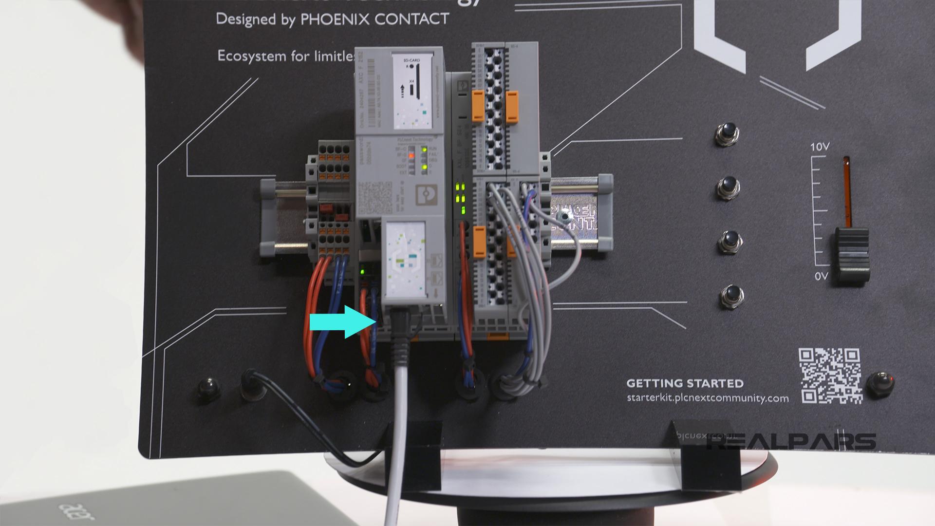
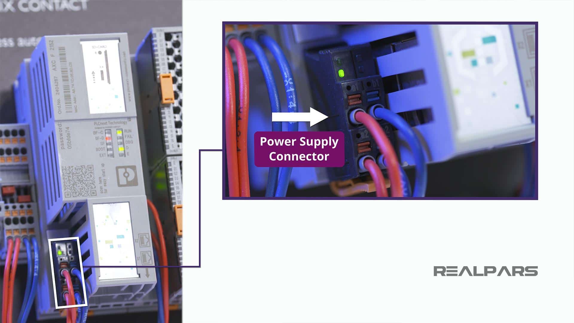
Power Supply Connector
At the bottom left of the controller is the Power Supply Connector.
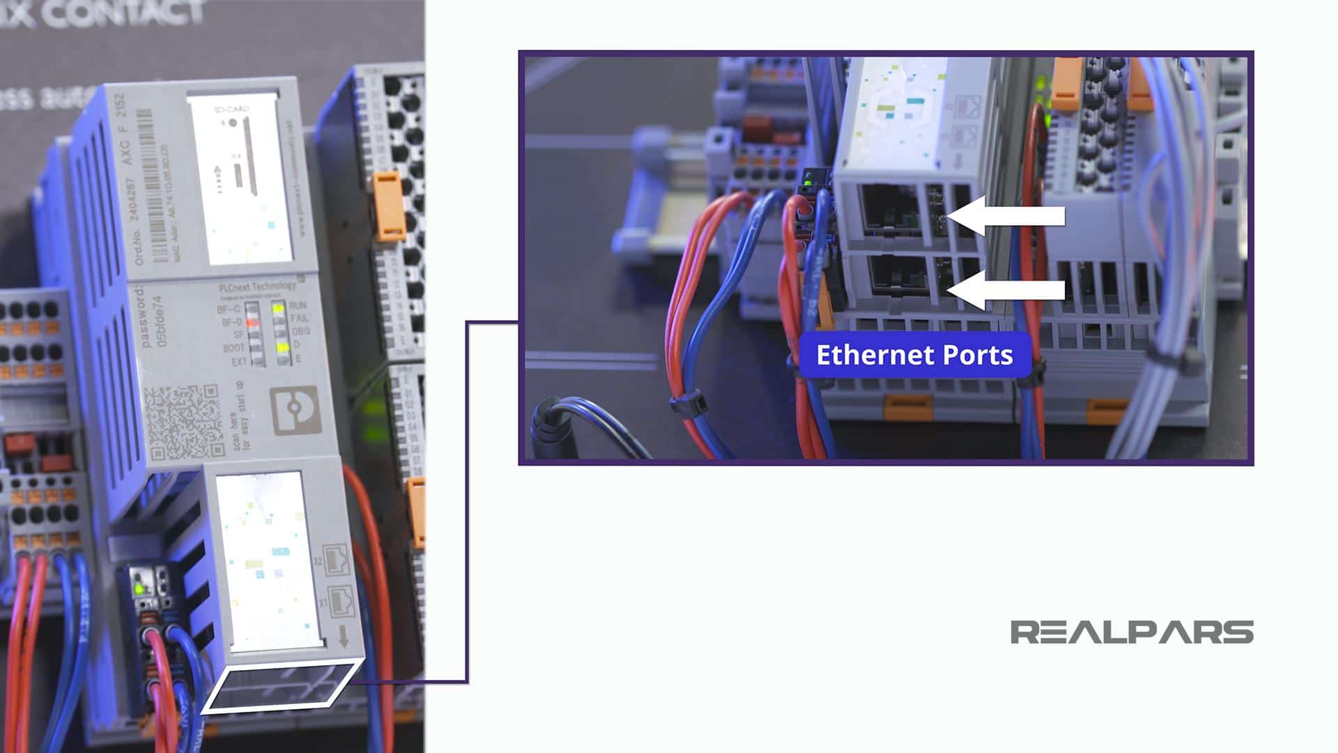
Ethernet ports
And, underneath the controller, you will find 2 Ethernet ports.
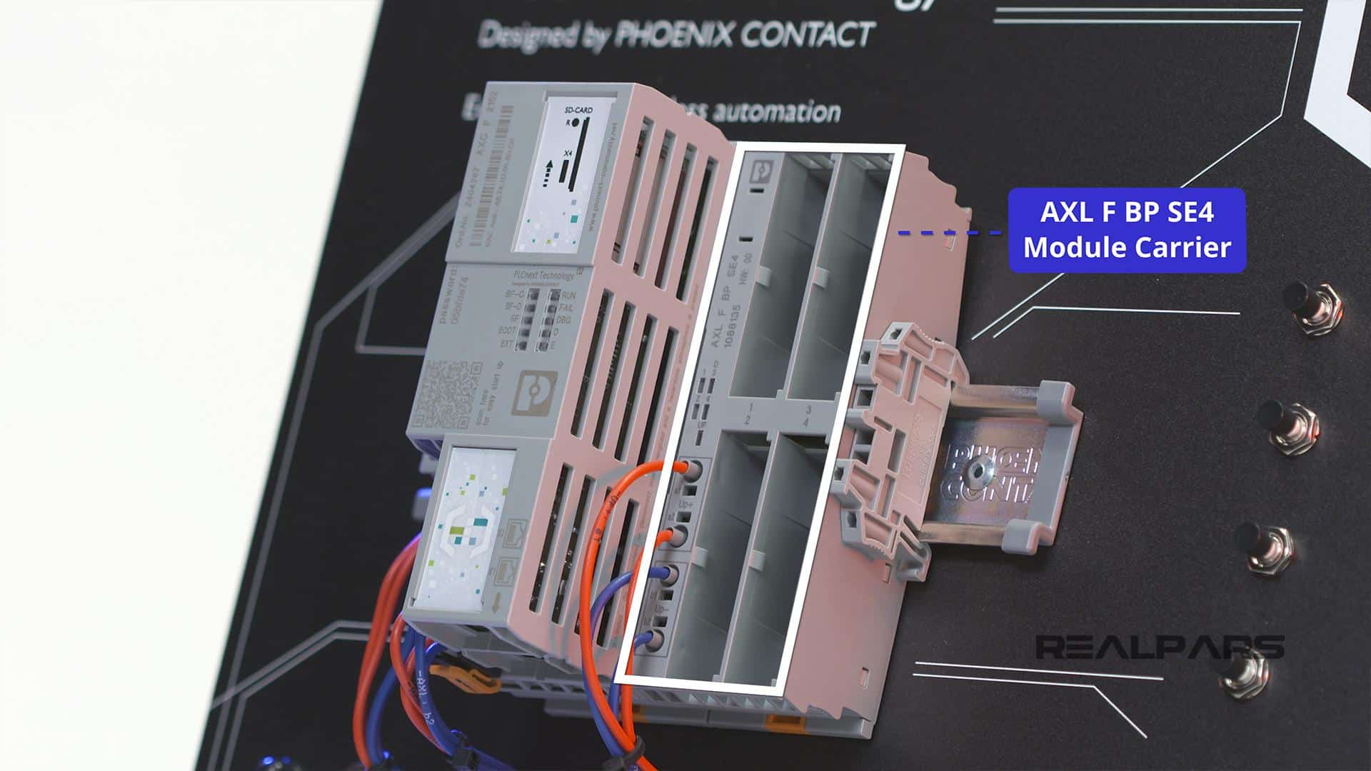
AXL F BP SE4 module carrier
Next on the panel is the AXL F BP SE4 Module Carrier which is the backplane allowing connections between the individual I/O modules, the power supply, and the controller.
I/O modules (smart elements)
Four I/O modules can be inserted into the Module Carrier. Phoenix refers to the I/O modules as Smart Elements.
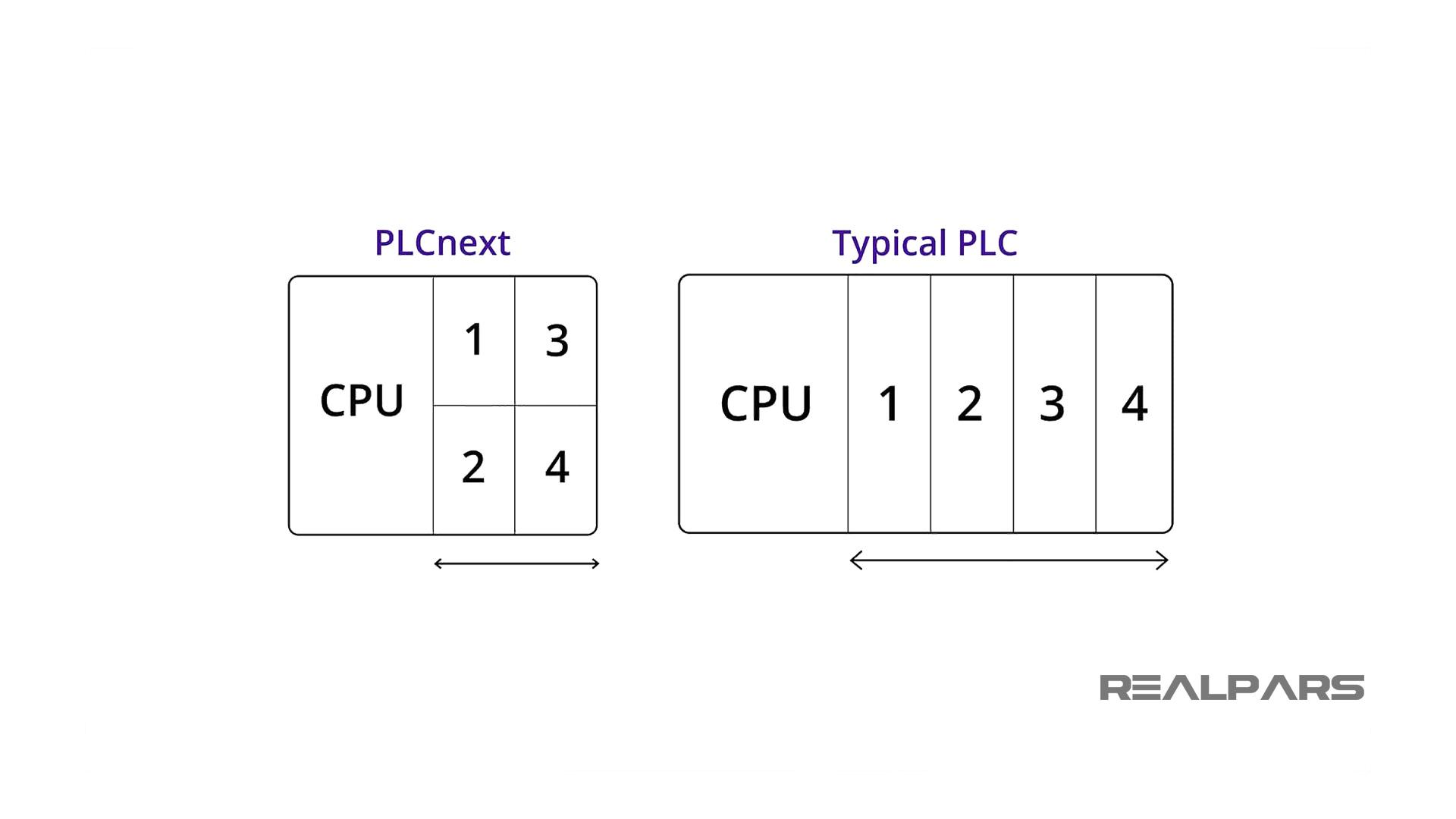
Here is one interesting fact about this PLC. In a typical PLC, when you have four input and output modules, you need to put the modules next to each other on the rack.
Now with this new PLC, having the same number of I/O modules takes half the space compared to using a typical PLC. This means in the same space that you could only have two modules, you can now have four modules instead.
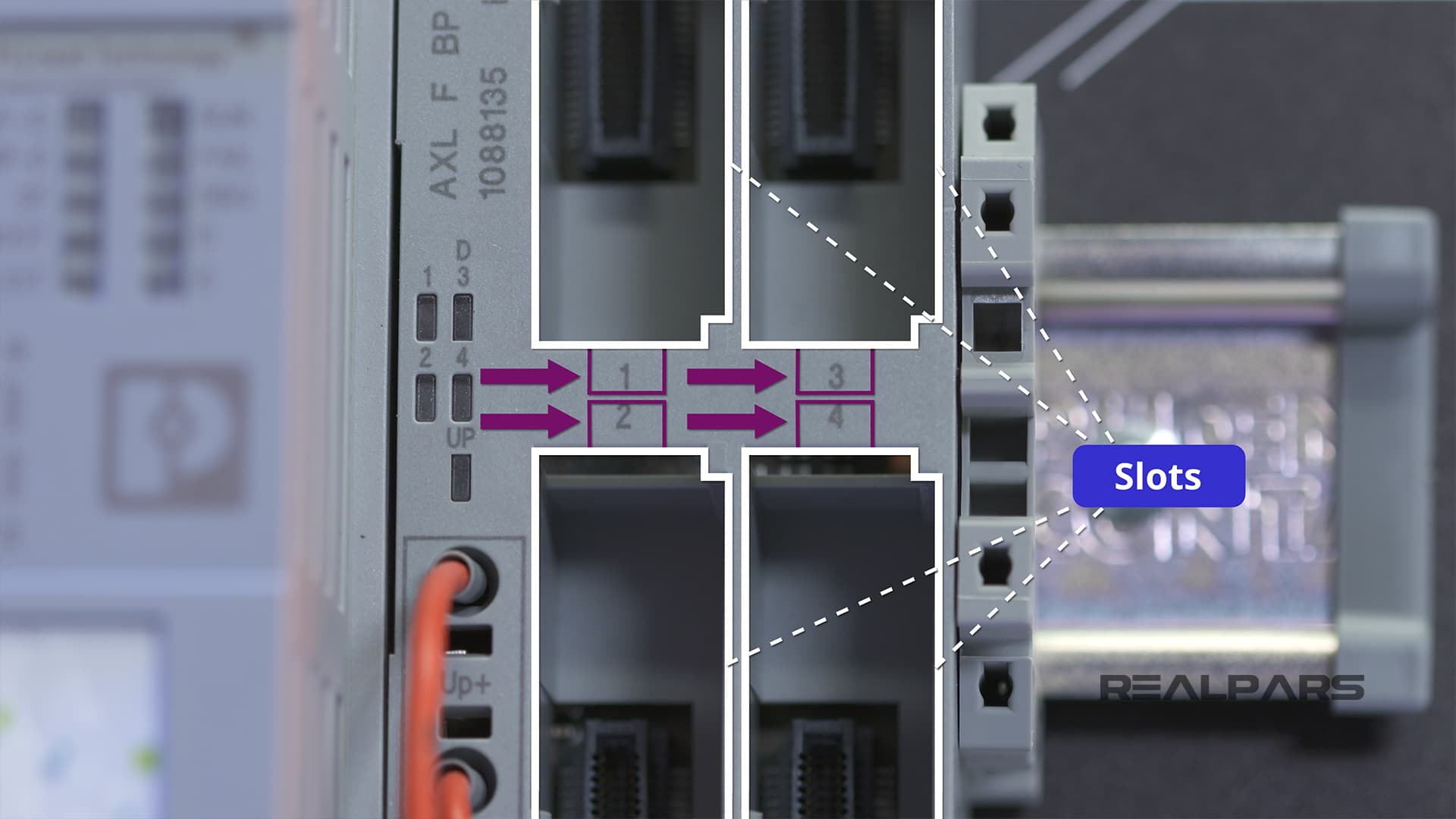
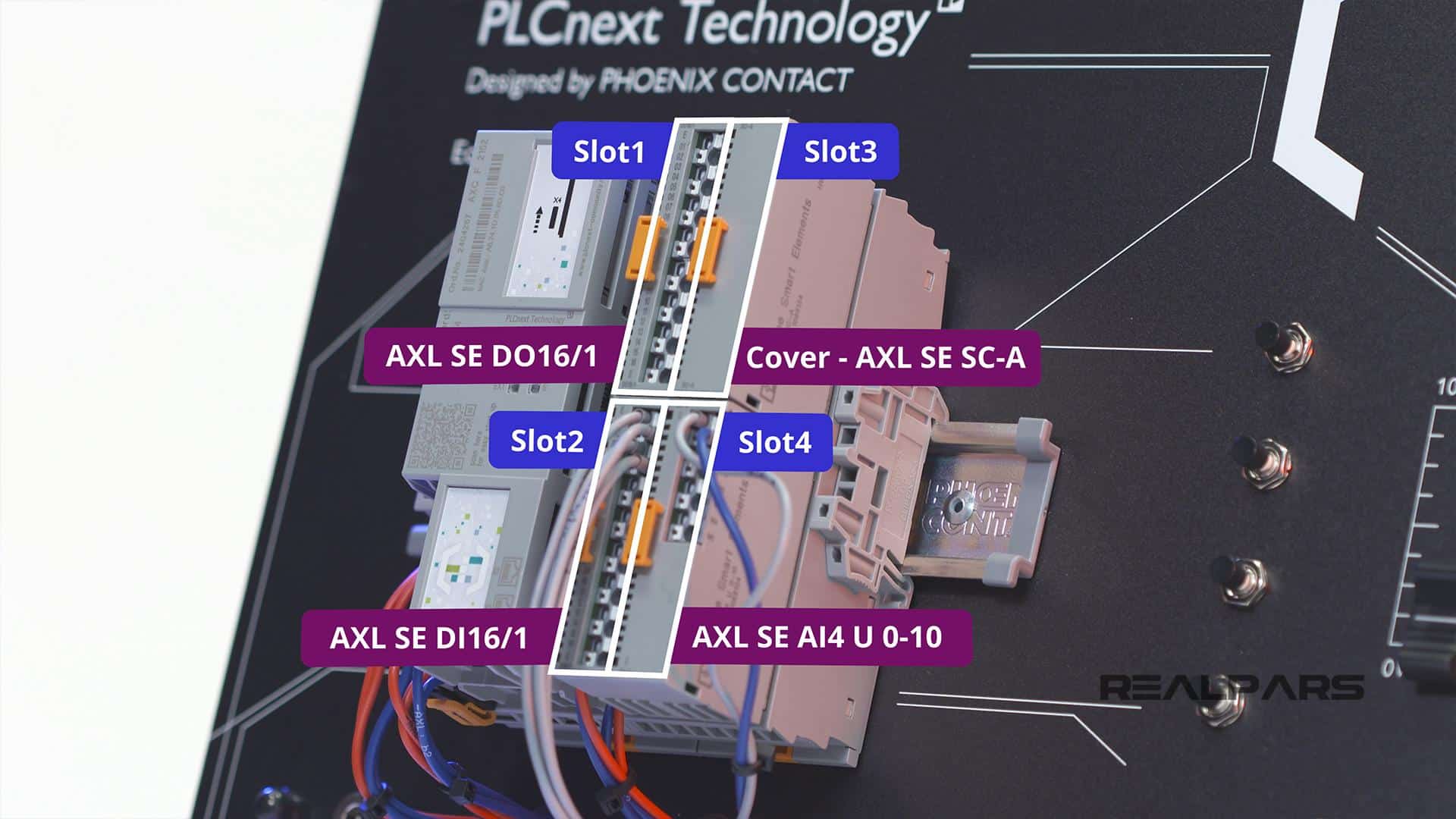
I/O modules are plugged into the slots and each module will have a dedicated Slot number.
You might want to make note of these slot numbers because they are not visible once the I/O modules are inserted.
We’ll tell you about the Module Status Indicators in the next article, How to Configure the PLCnext Starterkit I/O Modules and Establish Ethernet Communication.
Just a word of caution… If you decide to remove or insert an I/O module, be sure that the PLC is not powered!
OK… now it’s time to investigate the I/O Modules or Smart Elements that are included with the Starterkit.
The Module Carrier has 4 Smart Elements plugged into it.
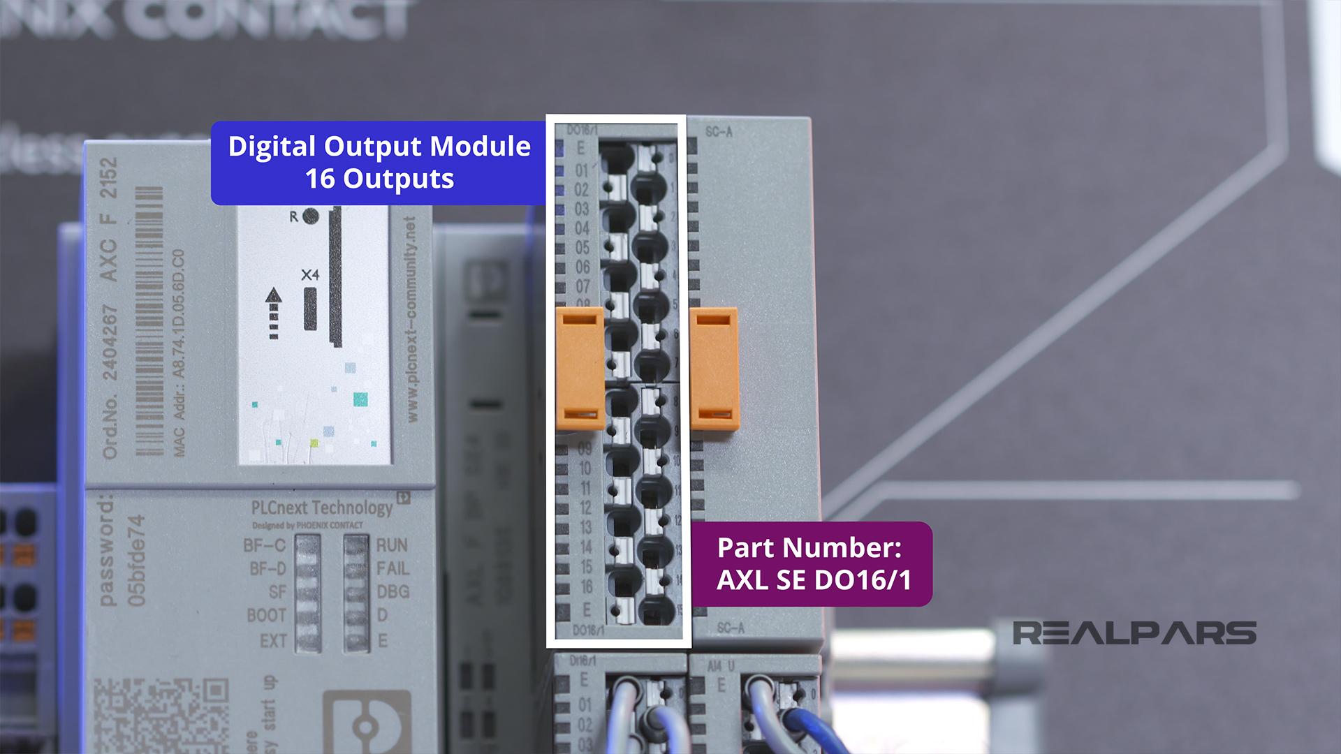
1) AXL SE DO16/1 digital output module
Slot 1 has a Digital Output Module with 16 outputs.
The Part number is AXL SE DO16/1.
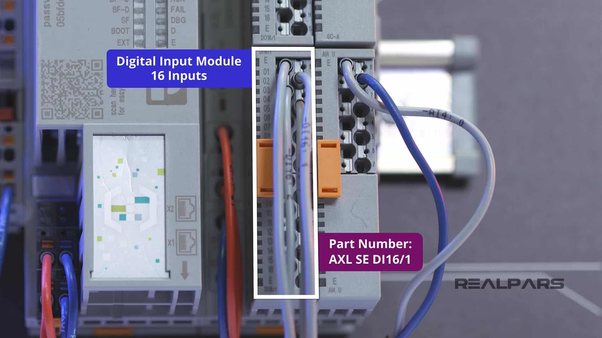
2) AXL SE DI16/1 digital input module
Slot 2 has a Digital Input Module with 16 inputs.
The Part Number is AXL SE DI16/1.
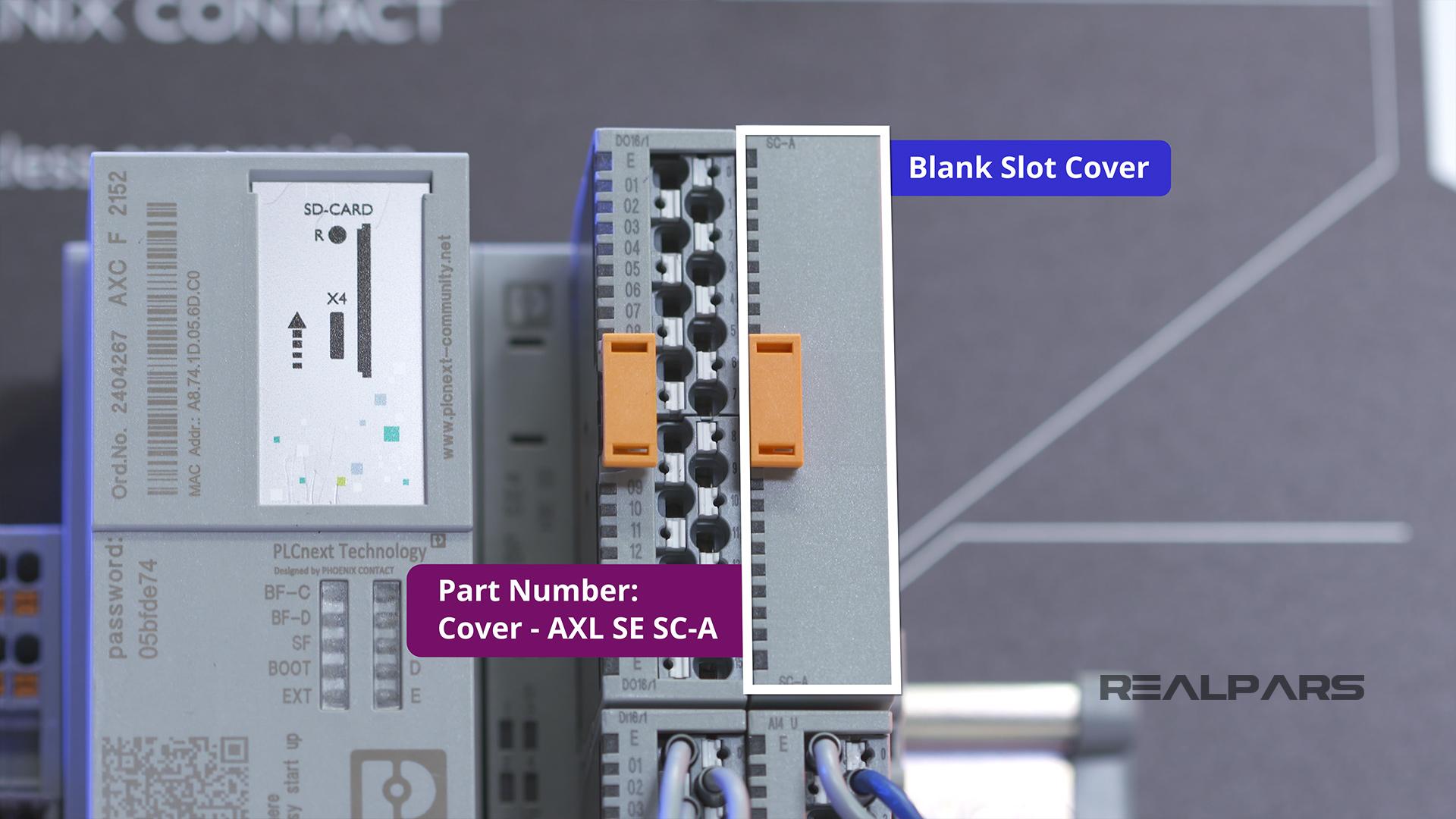
3) AXL SE SC-A Cover
Slot 3 has a blank or a Smart Element Cover.
The Part Number is Cover – AXL SE SC-A.
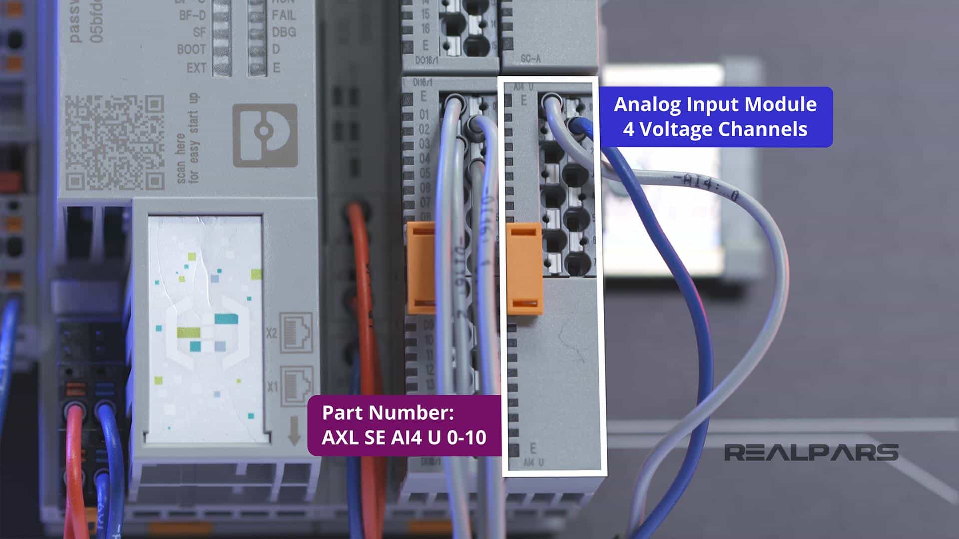
4) AXL SE AI4 U 0-10 analog input module
Slot 4 has an analog input module with 4 voltage channels.
The Part Number is AXL SE AI4 U 0-10.
Here’s something for you to remember for the next articles, How to Configure the PLCnext Starterkit I/O Modules and Establish Ethernet Communication, The Part Numbers and slot locations are very important for PLC and I/O configuration.
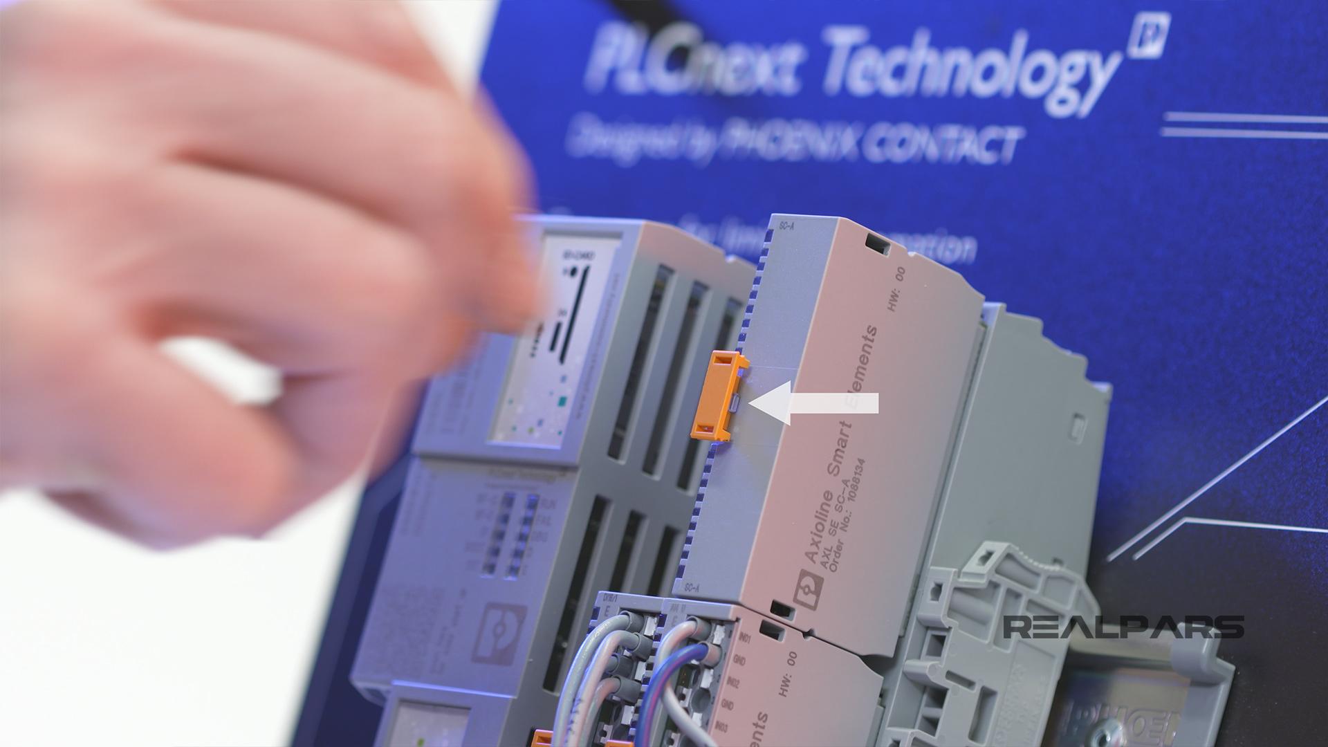
The modules can be removed and inserted by the orange tab.
Detailed specifications for each Smart Element can be found at phoenixcontact.com.
Starterkit field devices
Let’s move on to the Starterkit field devices.
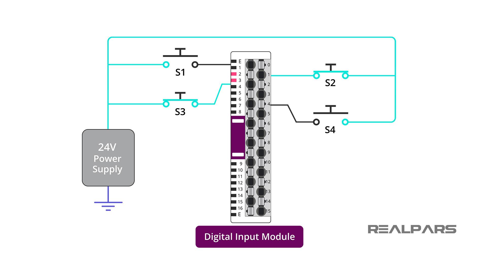
You will see 4 Pushbutton-Normally-Open switches to the right of the I/O modules. For our discussion, we’ve labeled them as S1 through S4.
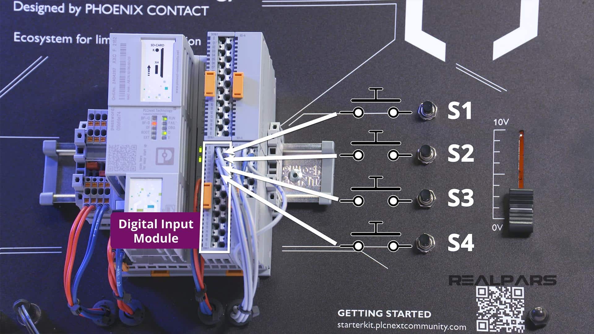
These switches are connected to the digital input module located in Slot 2.
If a switch is pushed, 24 volts will be applied to an input terminal. For example, pushing S3 will apply 24 volts to Input 3.
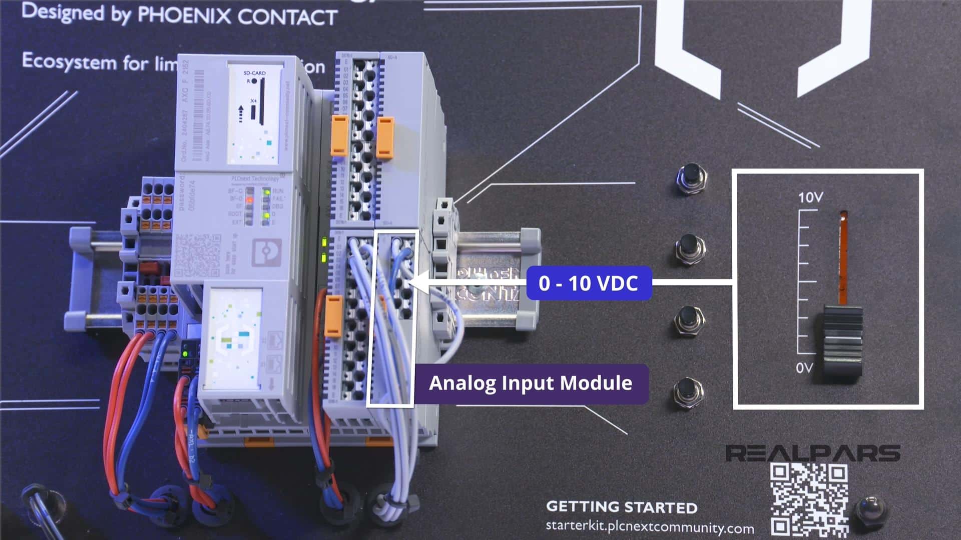
We’ve seen how the field devices are connected to the digital input module so now let’s explore the field device connected to the analog input module.
There is a Slider that provides an adjustable voltage from 0 to 10 volts DC directly to Channel 1 on the Analog Input module.
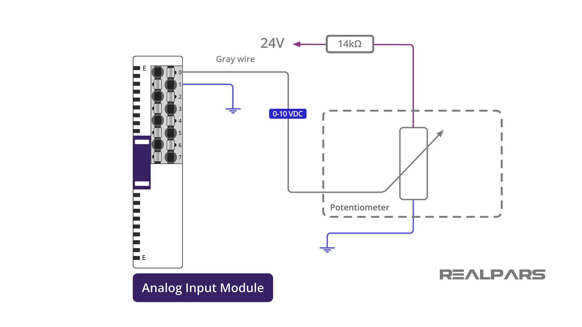
Let’s have a quick peek at how the Analog Voltage Input Adjustment is wired and connected to the analog input module.
As discussed earlier, the Analog module will accept an input voltage range of 0 to 10 volts. There is a voltage divider circuit connected to the 24 volt supply to ensure that the voltage applied to the analog input card never exceeds 10 volts.
The gray wire connects the variable voltage from the potentiometer to the positive input terminal of Channel 1 of the analog input card. The negative input terminal of the analog input card is connected to the negative terminal of the 24-volt power supply.
Here’s a small challenge for you… Using your electronic circuit knowledge, can you confirm that this voltage divider circuit design will perform as needed?
Here’s a small challenge for you… Using your electronic circuit knowledge, can you confirm that this voltage divider circuit design will perform as needed?
Summary
That should do it for this article! Let’s have a quick review and highlight some key points.
– The Starterkit comes with its own 24 Volt DC power supply.
– The protocol used to communicate between your computer and the Starterkit is Ethernet, and an Ethernet cable is provided.
– SD-CARD Expansion is available.
– The Administration Password is written on the front face of the Controller.
– There are 3 Smart elements, or I/O modules available for your use:
- A digital input module
- A digital output module
- An analog input module
– The digital input module and the analog input module have field devices connected to them for your use.
▶ PLCnext Starterkit | What’s in the Box? (Part 1 of 4)
How to Create a New PLCnext Engineer Project and Configure Ethernet Port (Part 2 of 4)
How to Easily Create PLCnext Ladder Logic Programs (Part 4 of 4)
Got a friend, client, or colleague who could use some of this information? Please share this article.

Learn from
Industry Experts
With a 7-day trial, then €25/month