In the first article of this 2-part series, we showed you how a Differential Pressure Transmitter is used to measure the flow rate. This second part of our series will take you through the process of calibration and checking the output accuracy of a differential pressure flow transmitter.
If you haven’t already done so, you might want to review 2 of our other videos:
1) Differential Pressure Transmitter Explained
2) What is Sensor Calibration and Why is it Important?
In this article, we are going to:
– Describe how to correctly and safely remove a Differential Pressure Flow Transmitter from service
– Go through the steps involved in calibrating a Differential Pressure Flow Transmitter
– Describe how to correctly and safely return a Differential Pressure Flow Transmitter to service
Calibration Procedure
Removing the Transmitter from Service
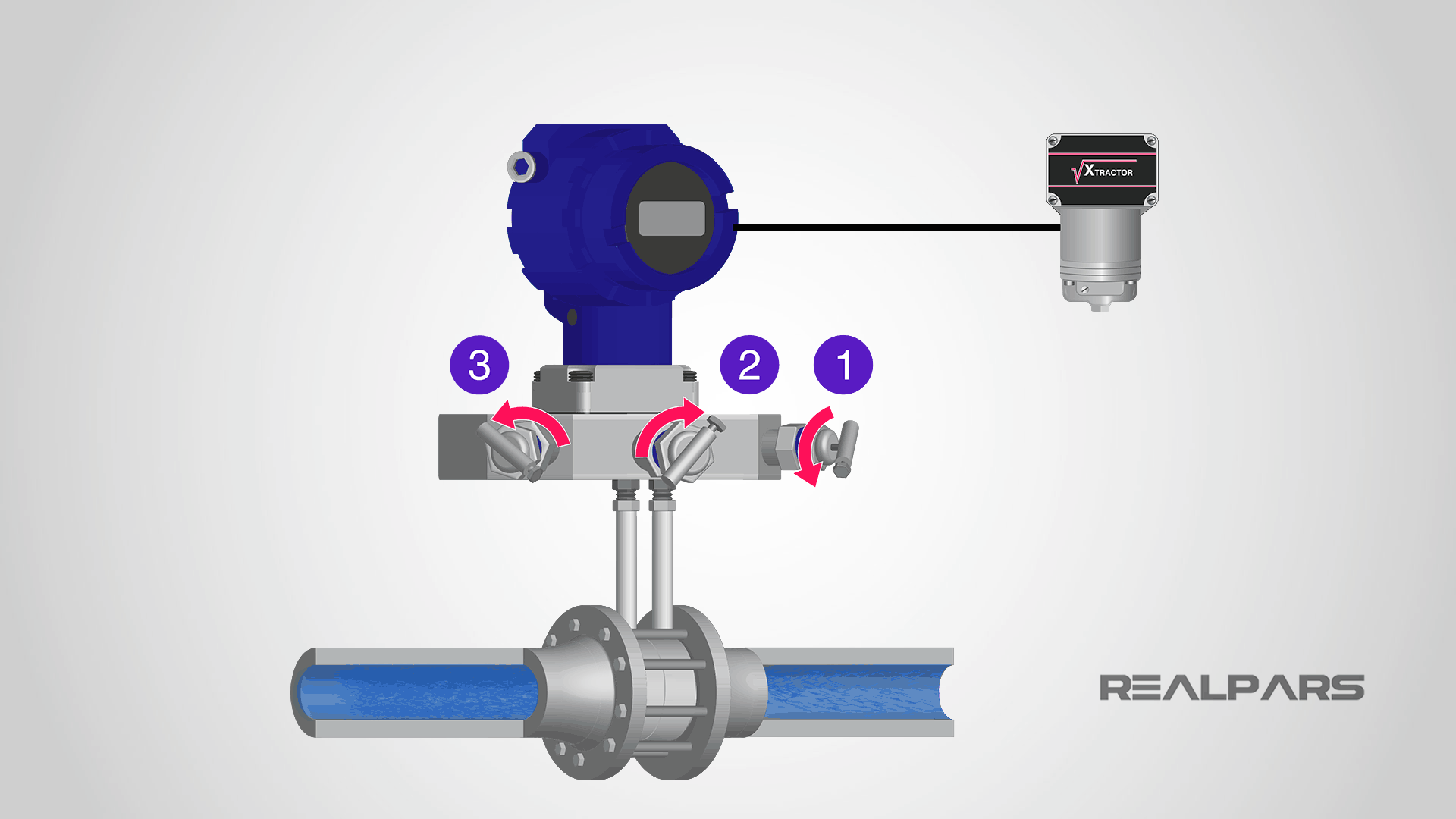
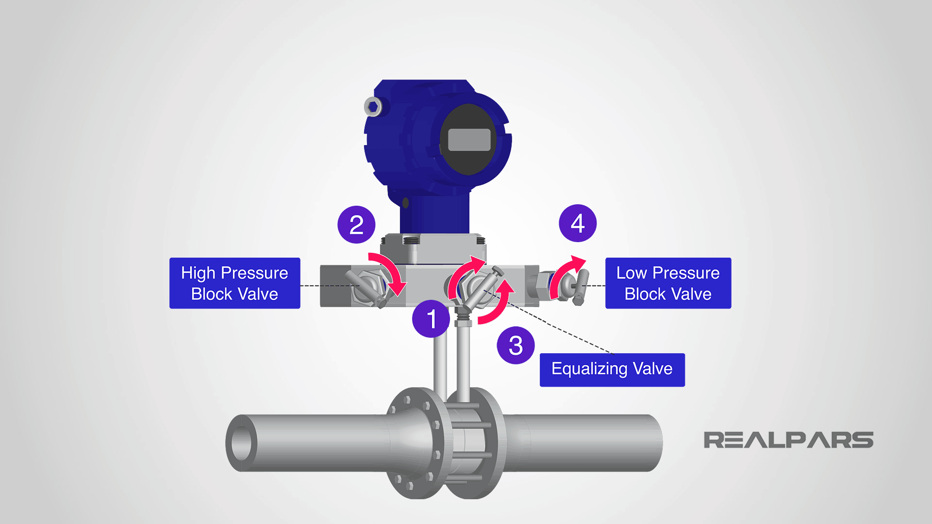
The transmitter must be removed from service before any checks or calibration can be performed. Let’s go through the following steps:
– Close the Low-Pressure Block Valve
– Open the Equalizing Valve
– Close the High-Pressure Block Valve
Ok, let’s go through the steps involved in checking and calibrating a Differential Pressure Flow Transmitter that has a separate square root extractor.
Here’s our situation; we have a flow system that will create a differential pressure of 200 inches of Water Column across an orifice at a flow rate of 50 gallons per minute.
Inches of Water Column Pressure Unit
In our example, we are using a non-SI pressure unit called inches of the water column. Inches of Water Column is one of several recognized pressure units and is very common in North America.
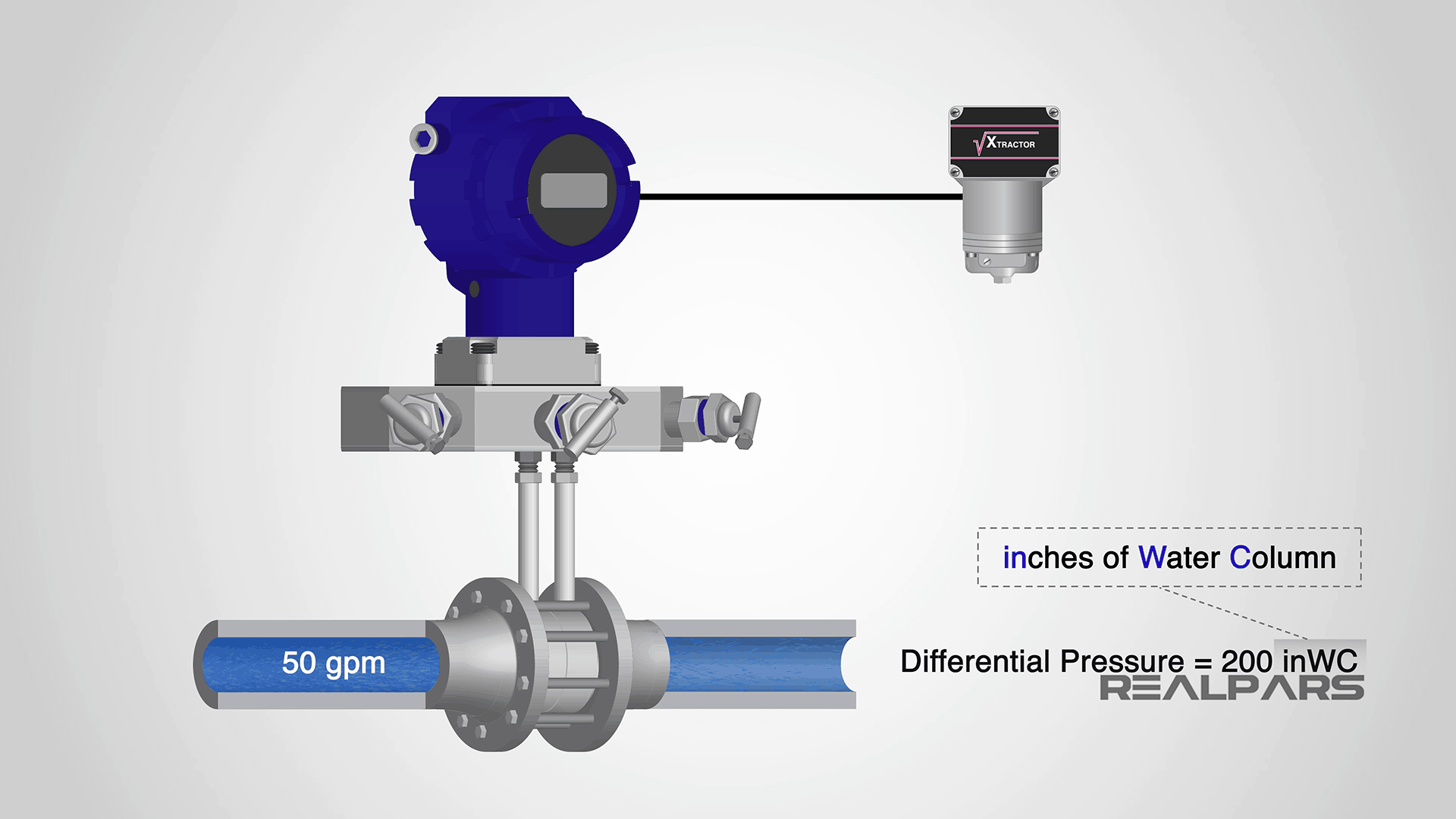
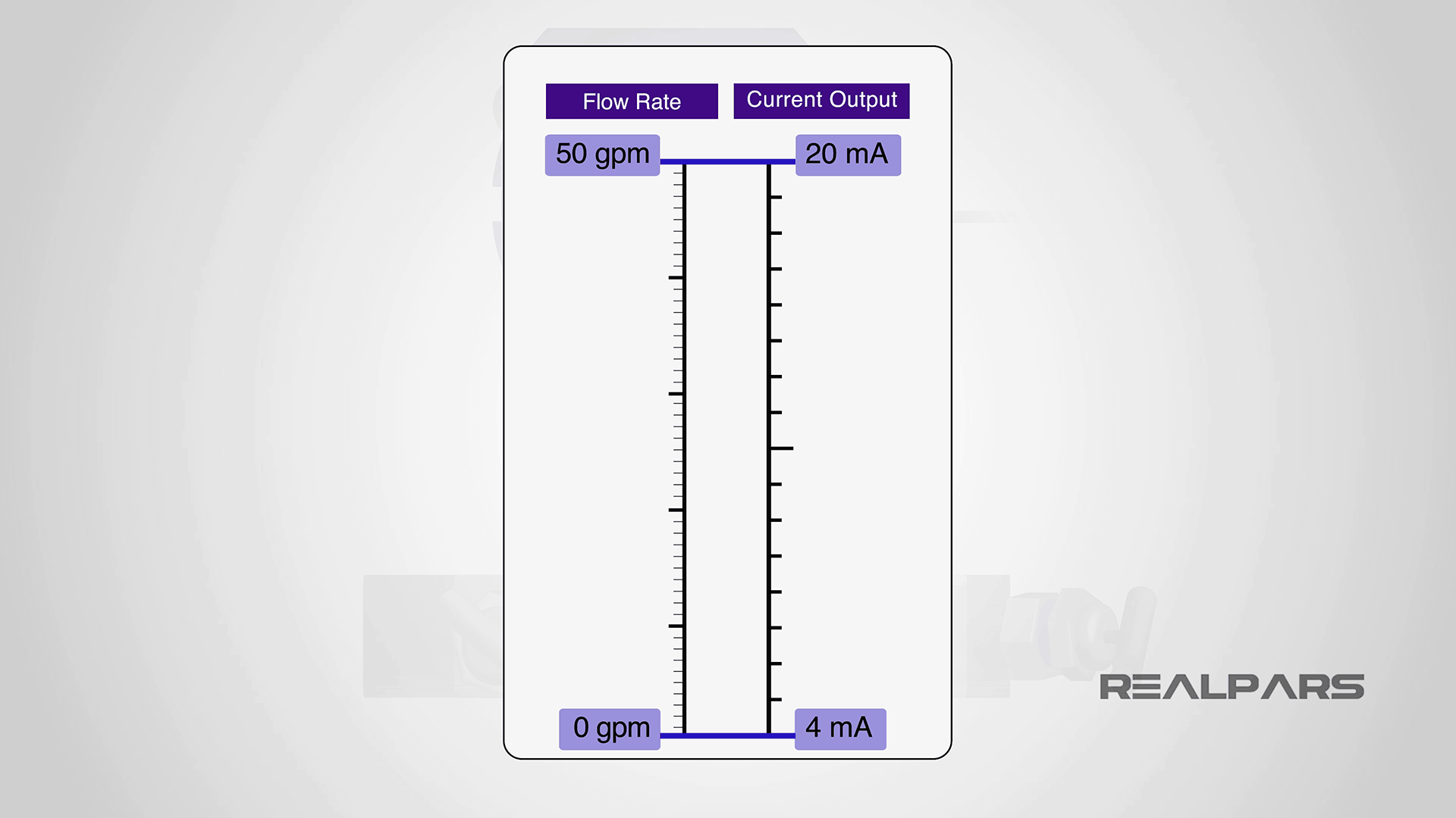
The Flow Transmitter connected across the orifice produces a current output of 4 milliamps at 0 gallons per minute and 20 milliamps at 50 gallons per minute. We need to check and recalibrate if necessary.
Calibration Chart
We are going to ignore the square root extractor for now as we will be looking at the output current from the flow transmitter.
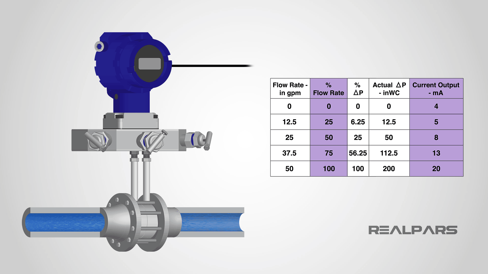
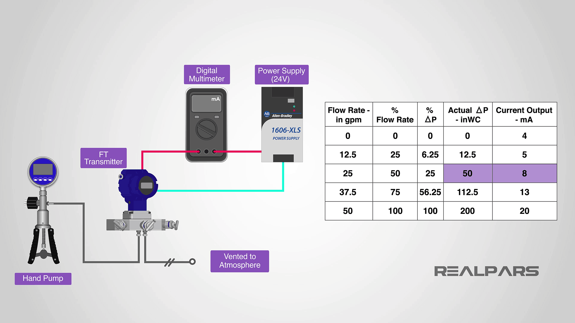
The first thing we need is a calibration chart or table. A table like this or similar is usually kept on file at your place of work.
This table is important from a calibration perspective as it indicates what we need to apply to the transmitter, and what the expected current output will be.
Calibration Setup
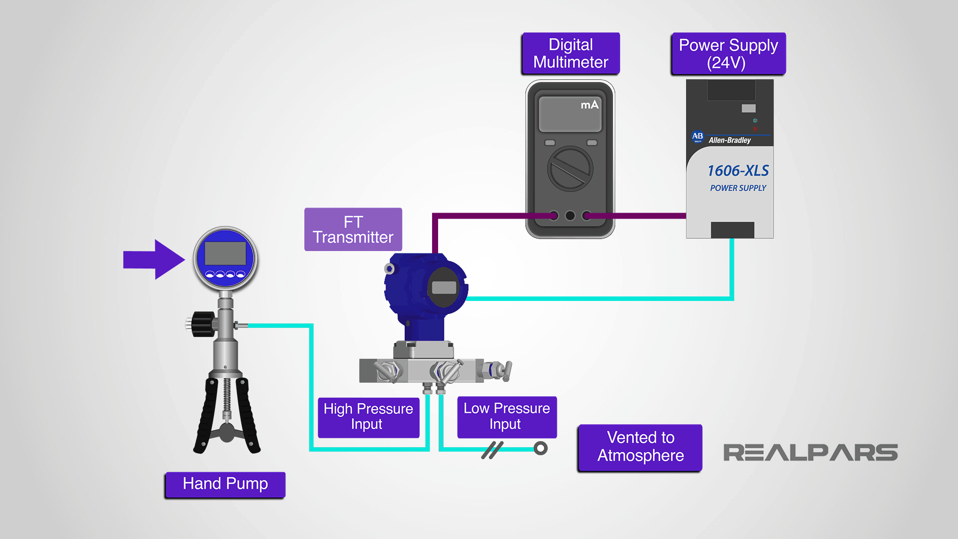
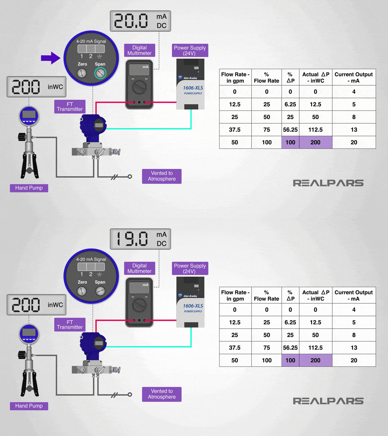
Here’s the calibration setup. The scissor-type hand pump with a digital pressure readout is connected to the high-pressure side of the transmitter.
There are several different types of pressure sources used in the industry. Note that the low-pressure side of the transmitter is vented to the atmosphere.
A digital multimeter set to measure current is connected in series with the transmitter and the 24-volt power supply.
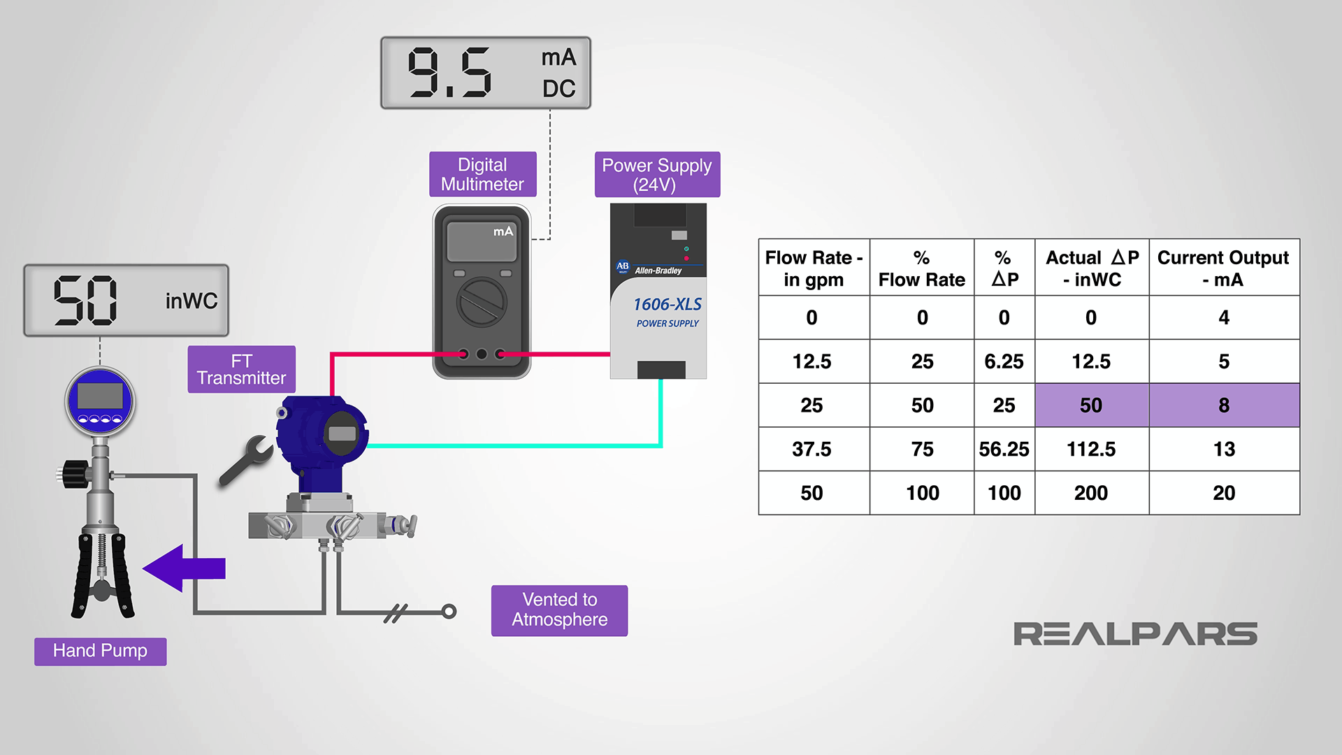
From the table, we can see that if we set the hand pump input pressure to 50 inches of Water Column, our multimeter should read 8 milliamps.
OK, now we’ve seen how the calibration table will work for us. We’ve got the transmitter all set up, let’s do some testing.
First of all, we’re going to check to see if the transmitter needs to be adjusted. We begin by applying the desired pressure input values from the calibration table to the high input on the flow transmitter and record the output current measured for each input value.
If the output currents measured are outside of the acceptable ranges as established by your company, then the transmitter must be recalibrated using the Zero/Span adjustments.
We perform the actual calibration using the Zero/Span adjustments on the transmitter
Apply the 0% input pressure value, which for us is 0 inches Water column, to the transmitter and adjust the Zero until we get an output current of 4 milliamps.
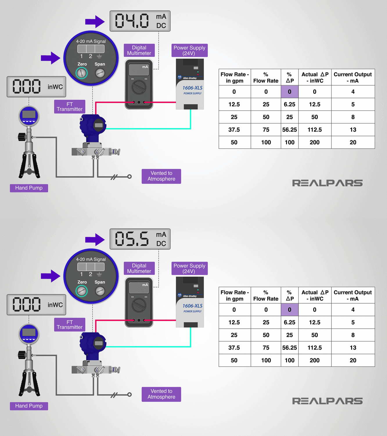
Apply the 100% input pressure value, which for us is 200 inches Water Column, to the transmitter and adjust the Span until we get an output current of 20 milliamps. Repeat the steps until adjustments are no longer required.
Returning the Transmitter to Service
Now that you’ve recalibrated, it’s a good idea to apply all of the values from the calibration table and record the corresponding output current values.
Let’s return the transmitter to service now that it’s been calibrated.
– Begin with all valves closed
– Open the equalizing valve
– Open the High-Pressure Block Valve (slowly)
– Close the equalizing valve
– Open the Low-Pressure Block Valve
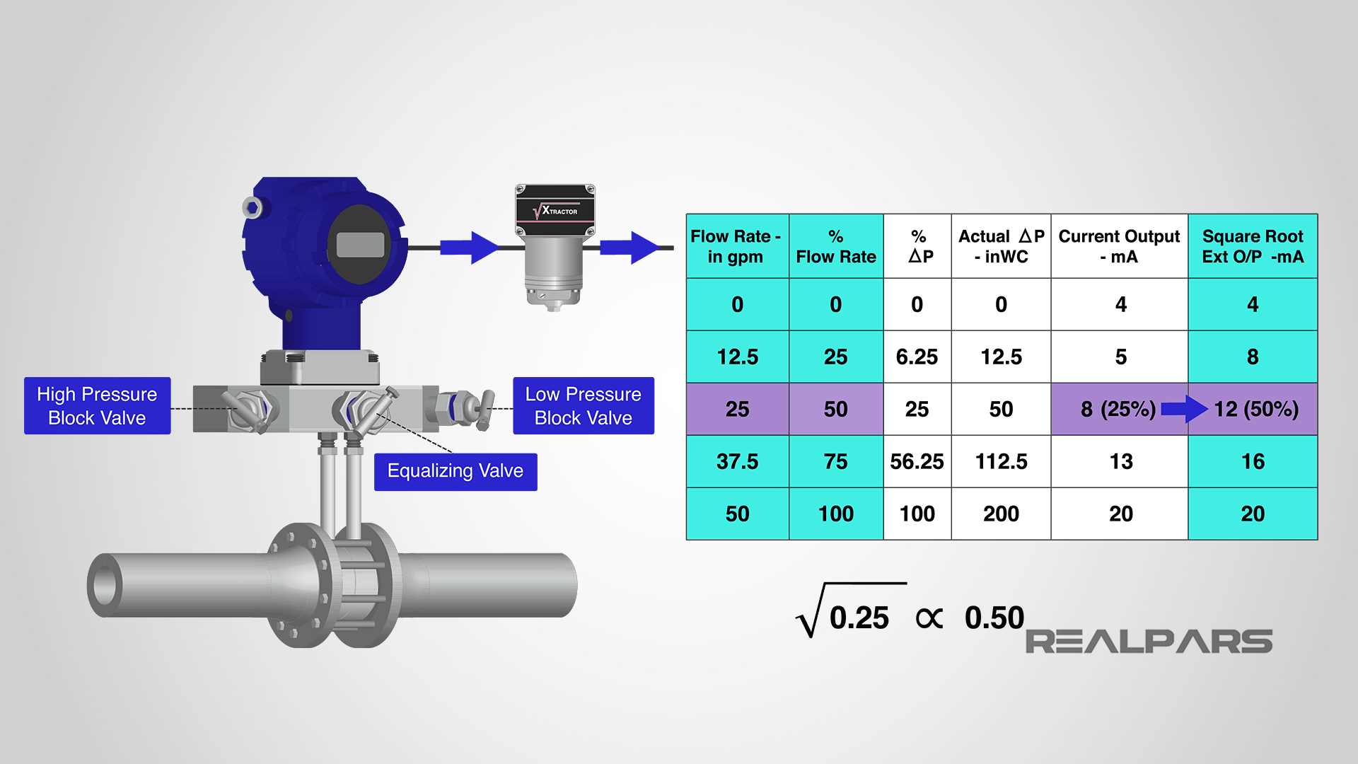
Remember, we ignored the square root extractor when we calibrated the transmitter. Let’s connect the square root extractor to the output of the transmitter and see what happens.
We now have a linear and directly proportional relationship between the flow rate and the current output of the square root extractor. Perfect! That’s exactly what our PLC or DCS needs to see.
The math is a bit complicated, but let’s try an example. When we have a 50% flow rate of 25 gallons per minute, the square root extractor output is 12 milliamps, or 50% as well. But, the Flow transmitter output is 8 milliamps or 25%.
How do we convert 8 milliamps to 12 milliamps?
Very simply, the square root extractor will ensure that its output is the square root of its input.
The square root of 25% is 50%! Try the math on a calculator. So, with a Flow Transmitter output current of 8 milliamps, the square root extractor will produce an output current of 12 milliamps.
Summary
Let’s review what we’ve discussed.
– Before calibration, a transmitter must be removed from service by closing the Low-Pressure Block Valve first, then opening the Equalizing Valve second, and finally closing the High-Pressure Block Valve.
– Checking and calibrating the transmitter is completed by using values found in a Calibration Table or Chart kept onsite. The Zero/Span adjustments are used to obtain a specific current output range for a 0% and a 100% differential pressure input.
– After calibration, a transmitter is returned to service by opening the Equalizing Valve first, then opening the High-Pressure Block Valve second, followed by closing the equalization valve, and finally opening the Low-Pressure Block Valve.
Want to Learn More?
If you would like to get additional training on a similar subject please let us know in the comment section.
Check back with us soon for more automation control topics.
Got a friend, client, or colleague who could use some of this information? Please share this article.
The RealPars Team
How to Measure Flow Rate with a DP Transmitter (Part 1 of 2)
DP Flow Transmitter Testing and Recalibration (Part 2 of 2)

