
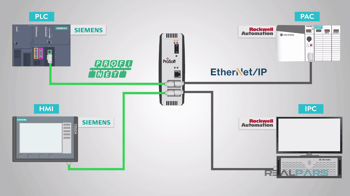
As you may have learned in previous videos and articles, automation often requires communication between heterogeneous systems from different manufacturers.
Each manufacturer offers a proprietary or an open form of a communication protocol.
It is the responsibility of the Automation Engineer or Technician to configure devices and develop program logic to communicate between systems.
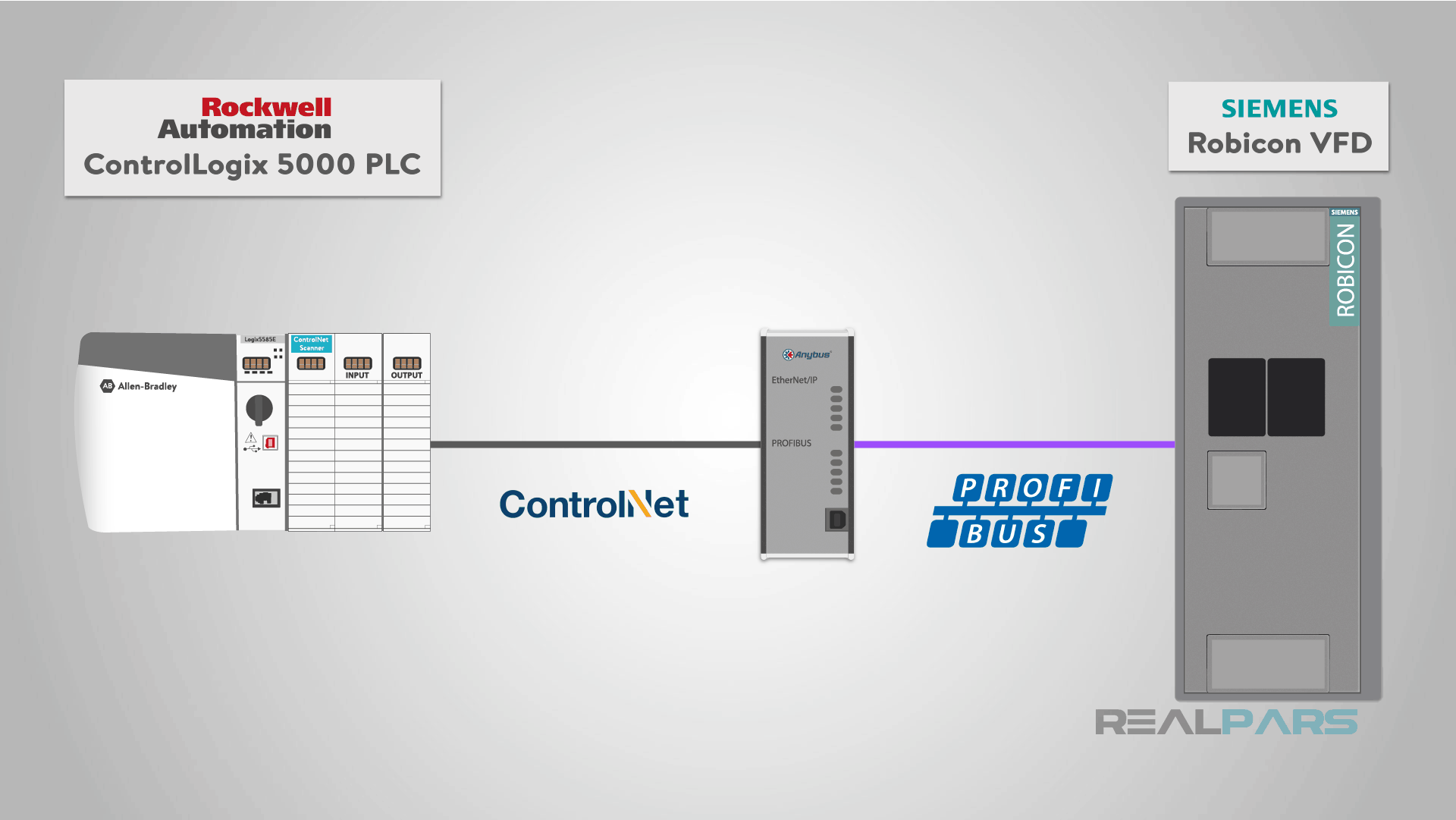
In this article, we will discuss how a Rockwell Automation ControlLogix 5000 PLC using ControlNet network media and CIP protocol will overall communicate with a Siemens Robicon VFD using Profibus protocol.
However, these two systems will need a device to help translate the two heterogeneous protocols; this device is called a “proxy” or “gateway”.
In our example, we will use the Anybus X-gateway AB7803 “Profibus Master” to “ControlNet Adapter” gateway from HMS.
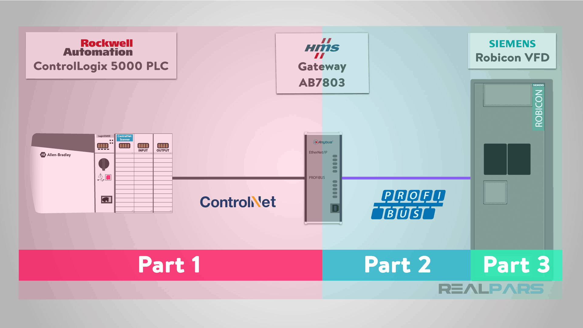
Part 1 of this lesson, will address the configuration of the ControlLogix 5000 PAC to the HMS Anybus gateway.
Part 2 of this lesson will address the HMS Anybus Profibus Master configuration and Part 3, will address the Siemens Robicon Profibus slave configuration.
PLC and VFD Communication Overall Data Flow
First, let’s review the overall communication configuration we will perform to allow communication between the “ControlLogix PLC” and “Siemens Robicon VFD” using the “HMS Gateway” used in our example.
The ControlLogix PAC will be controlling a pump with a simple ON/OFF command and its velocity by setting a speed set-point to the VFD (variable frequency device).
In response, the Siemens VFD will return the actual speed reference and VFD status information controlling the pump.
This exchange of control data and status information is all performed by the HMS gateway. The HMS Gateway also performs an important responsibility as “Profibus Master”, controlling the Pump VFD.
Addresses Configuration for VFD and PLC Communication
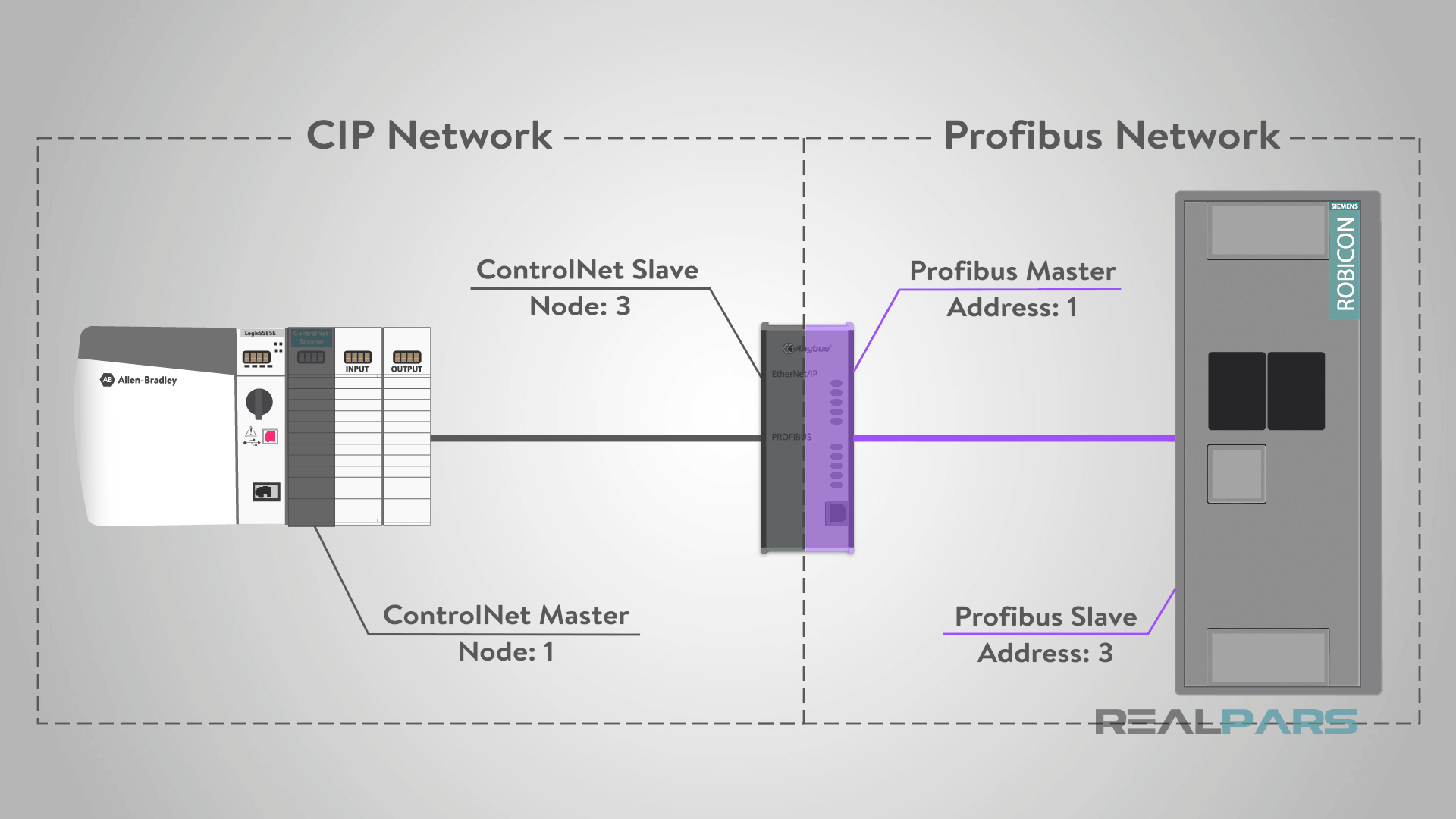
We have specific addressing for each side of our network;
On the left-hand side of the network, the ‘CIP network’, the ‘ControlNet Master’ or ‘Scanner’ will be addressed as ‘Node 1’ and the ‘HMS Gateway’ will be addressed as ‘Node 3’.
On the right-hand side of the network, the ‘HMS Gateway’ will be the ‘Profibus Master’ and will have the address of ‘1’ and the ‘Robicon VFD’ will have the ‘Slave address’ as ‘3’.
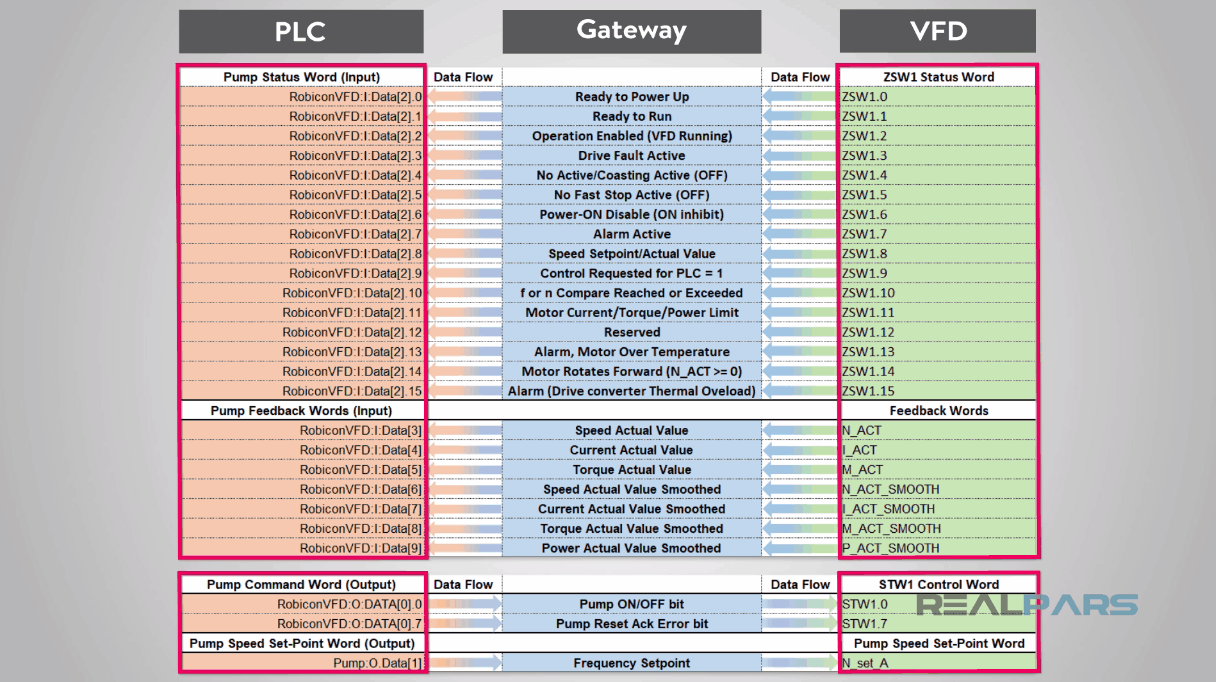
VFD and PLC Communication I/O List
Please note, when beginning a communication project, it is best to look at the big picture and create a spreadsheet with all the tags and data types to be configured at each system.
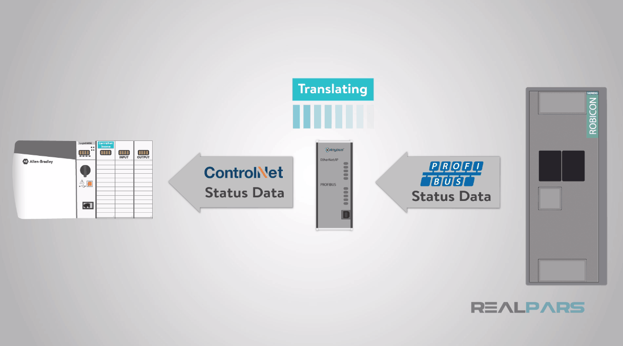
I want to point out that the HMS Anybus gateway is not pass-thru but instead acts as a “translator” using an internal shared common database.
The communication is asynchronous, in that, the gateway serves two different communication loops, one for the ControlLogix 5000 ControlNet and one for the Siemens Robicon Profibus and the data is shared using an internal Dual Port ASIC RAM to the HMS gateway.
ControlLogix ControlNet communication to the HMS gateway
Ok, let’s get started with the ControlLogix ControlNet communication to the HMS gateway. We will configure the ControlLogix IO configuration first.
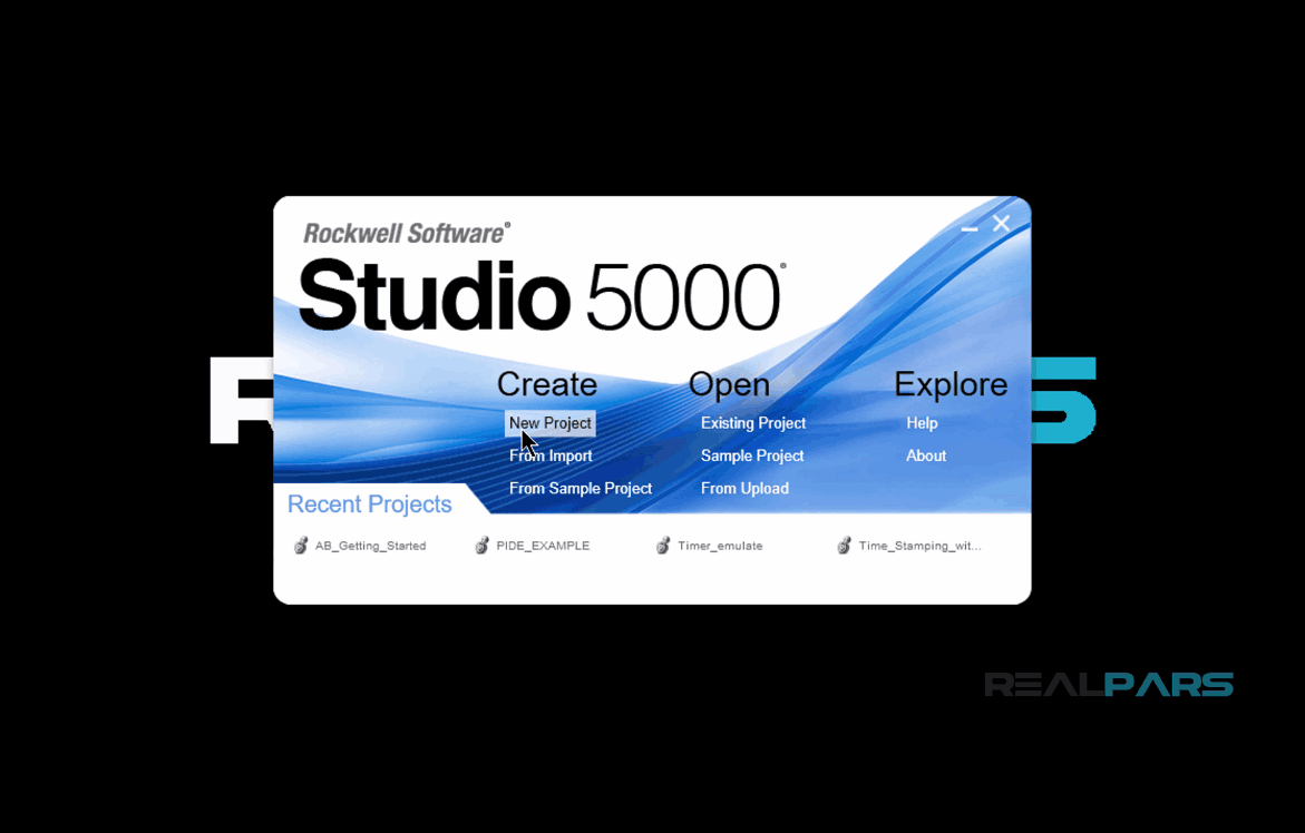
We are assuming that the user is familiar with the basics of Studio 5000 programming software.
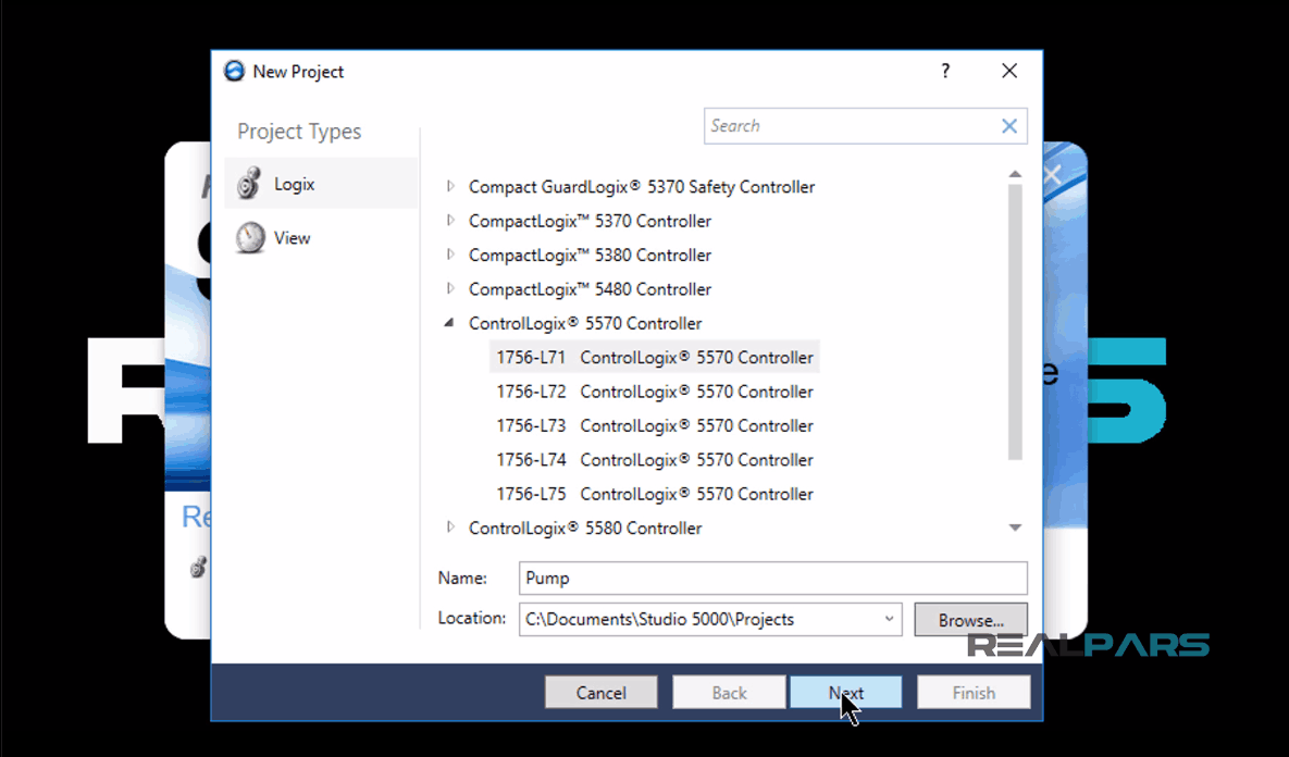
I will launch the studio 5000 and create a new project.
Next, I will select 1756-L71 processor, name the project as “Pump”, hit OK and then hit “Finish” as well.
Next thing that I need to do here is, under the “I/O configuration” folder, I’ll right click on the 1756 Backplane, and select “New Module”.
Then I’ll Locate the “1756-CNB ControlNet Bridge” module and press “create”.
In the next window, I’ll leave the “Major Revision” number as it is and hit OK.
Next, I will name the module as “Pump Control”, and press OK.
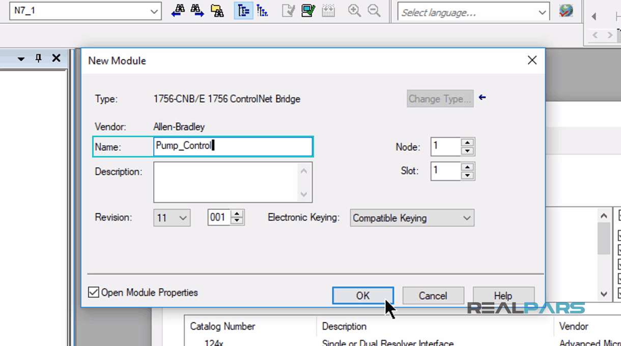
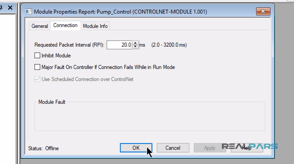
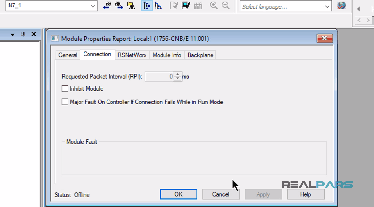
For “Module Properties Report” window, I will keep everything as it is and click OK again.
Next, I need to create a ControlNet communication module.
To do this, under the “I/O configuration” folder, I’ll right click over “1756-CNB/E Pump Control” and select “New Module”.
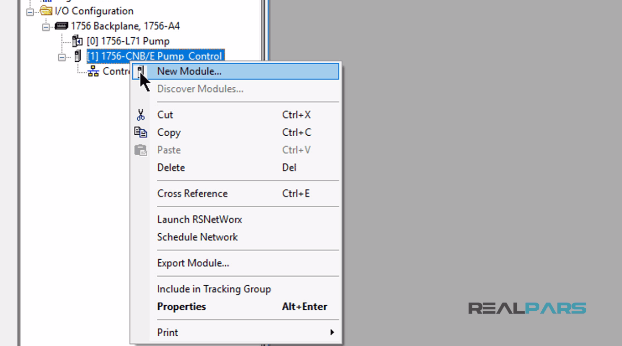
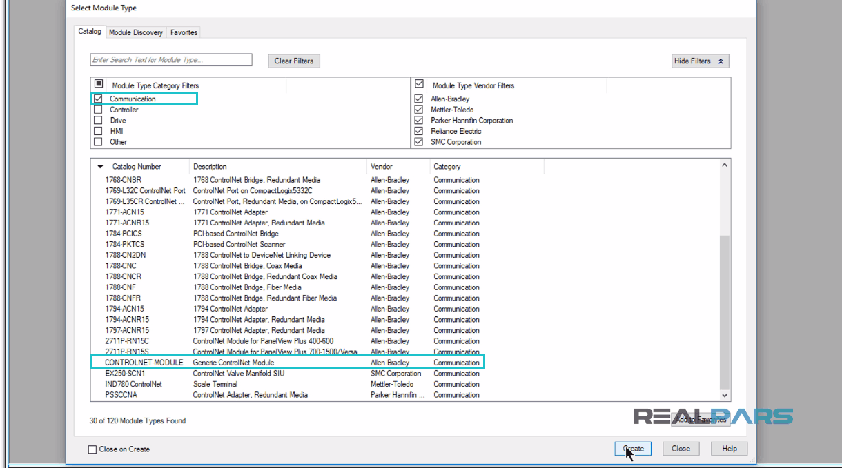
In the “Select Module Type” window, on the left side of the “Catalog” Tab, I will uncheck the “Module Type Category Filters” and select the “Communication”.
Then I’ll scroll down a bit until I will find the “Generic ControlNet Module”, and then I will press create.
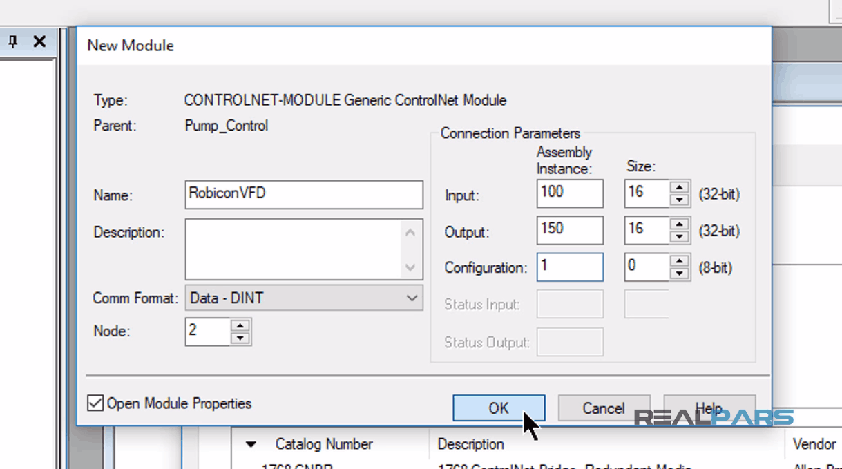
In the opening window, I will name this module as “RobiconVFD”, with the Node address of 2.
I will also set up the “Connection Parameters” with
– “Input Instance” of 100
– “Input Size” of 16
– “Output Instance” of 150
– Output Size” of 16
– Configuration Instance of 1.
After everything is done, I’ll click OK.
For “Module Properties Report” window, I’ll leave everything as it is and click OK again.
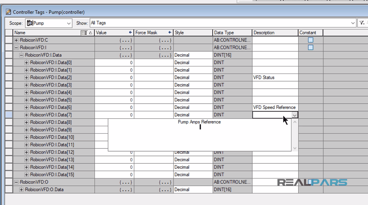
After the “ControlNet Generic Module” is created, Studio 5000 software automatically creates “Input” and “Output Controller” Tags for the RobiconVFD IO.
From the “I/O List” spreadsheet we will use:
– “RobiconVFD:I.Data[2]” as the “VFD status” word
– “RobiconVFD:I.Data[6]” as the “VFD speed reference”
– “RobiconVFD:I.Data[7]” as the “Pump Amps” reference.
In the Studio 5000 programming environment, I have created a routine and configured the PLC program logic in there.
In the first rung, rung zero, I have set the logic to move the input data from the VFD to Studio 5000 controller tags with alias tag names to easily identify the input data by its VFD origin.
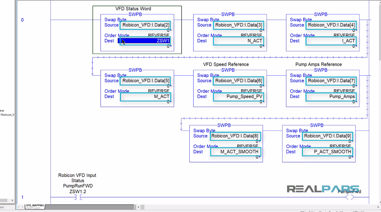
In the next rungs, rungs 1 and 2, you can see the “ZSW1” input status word-bits.
These bits are used as permissive to indicate the Pump is ON and or if the Pump is Faulted using the “PumpInFwd” and “PumpFaulted” tags respectively.
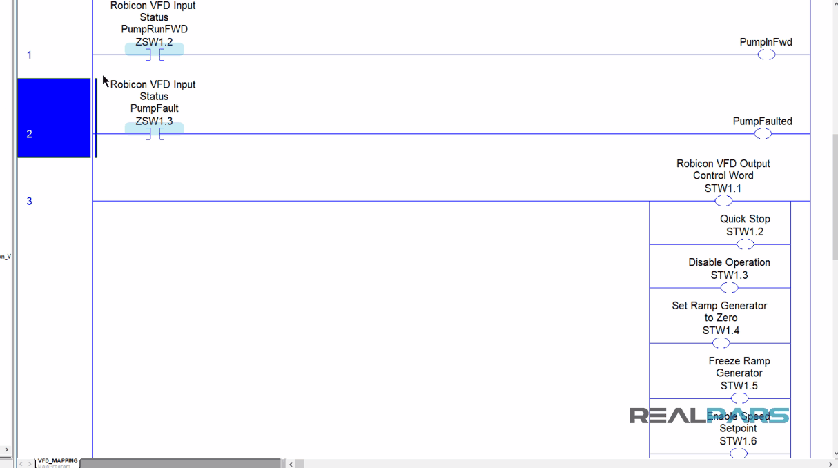
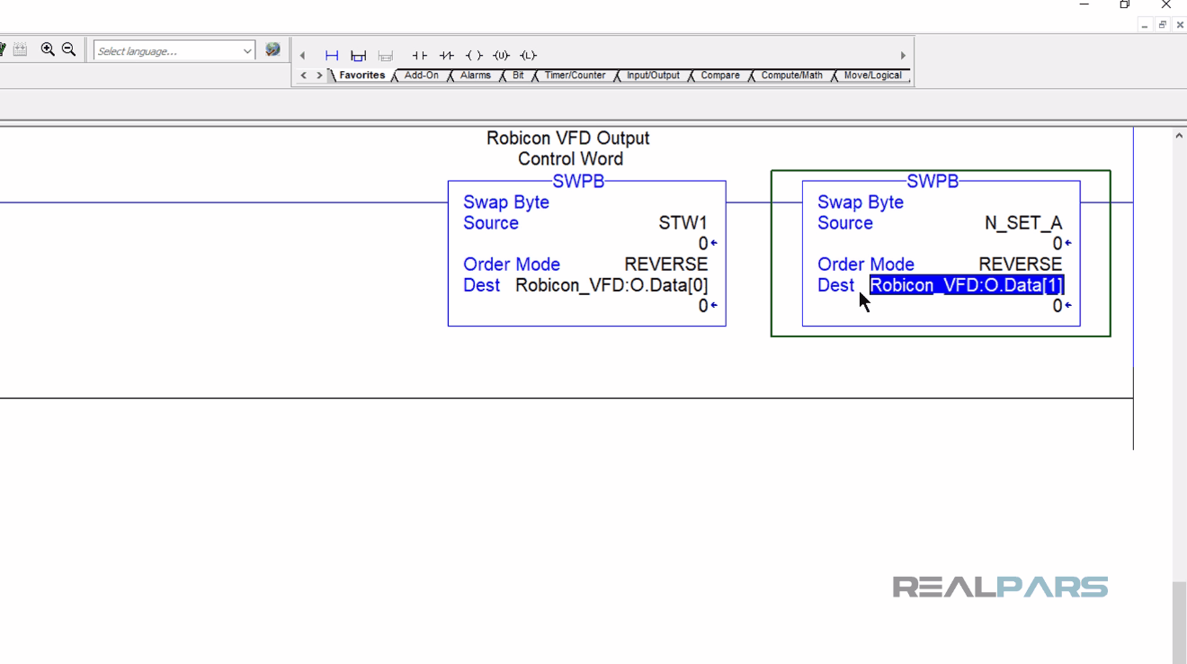
In rung 3, you can see the “ControlLogix Output Control Word” (STW1) bits will be forced “True” or “False” based on the VFD requirements.
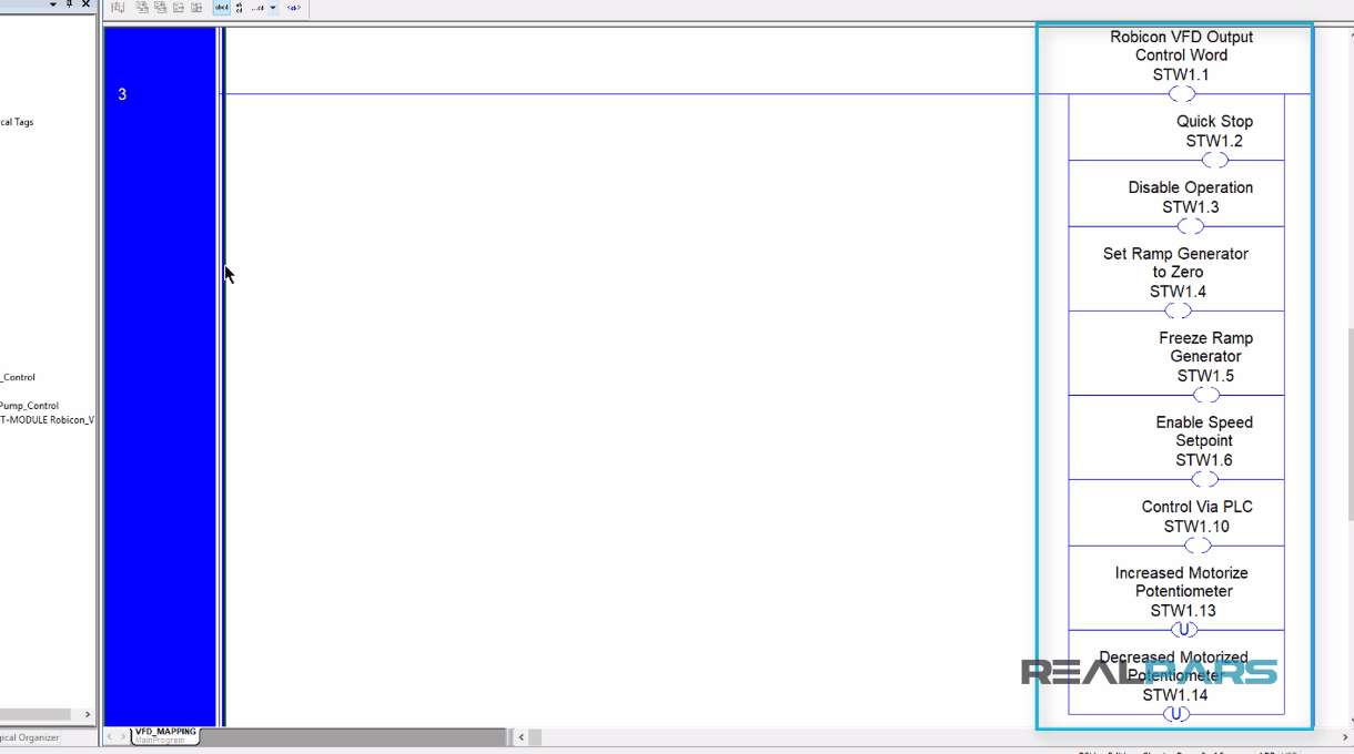
In the next rung, the output bits in the “STW1” VFD control word are moved to the ControlNet relevant word, “RobiconVFD:O.Data[0]” and the Speed Setpoint, “N_set_A” tag is also moved to its ControlNet relevant word, “RobiconVFD:O.Data[1]”.
At this point, ControlLogix ControlNet module will “Read” and “Write” the ControlLogix processor data to and from the HMS Gateway for translation into the Profibus language to be processed in milliseconds and communicated to the Siemens VFD for pump control.
PLC and HMS Gateway Communication Configuration
As we mentioned earlier, the HMS gateway provides a kind of translation for Siemens Robicon VFD and the ControlLogix 5000 systems.
In our example, in the CIP Network, HMS Gateway is the “ControlNet Slave” to the ControlLogix and in the Profibus Network, is the “Profibus Master” to the Siemens VFD.
Generally, the gateway requires very little effort to get it up and running. However, since all networks are different, certain settings may need to be adjusted slightly to fit a particular application.
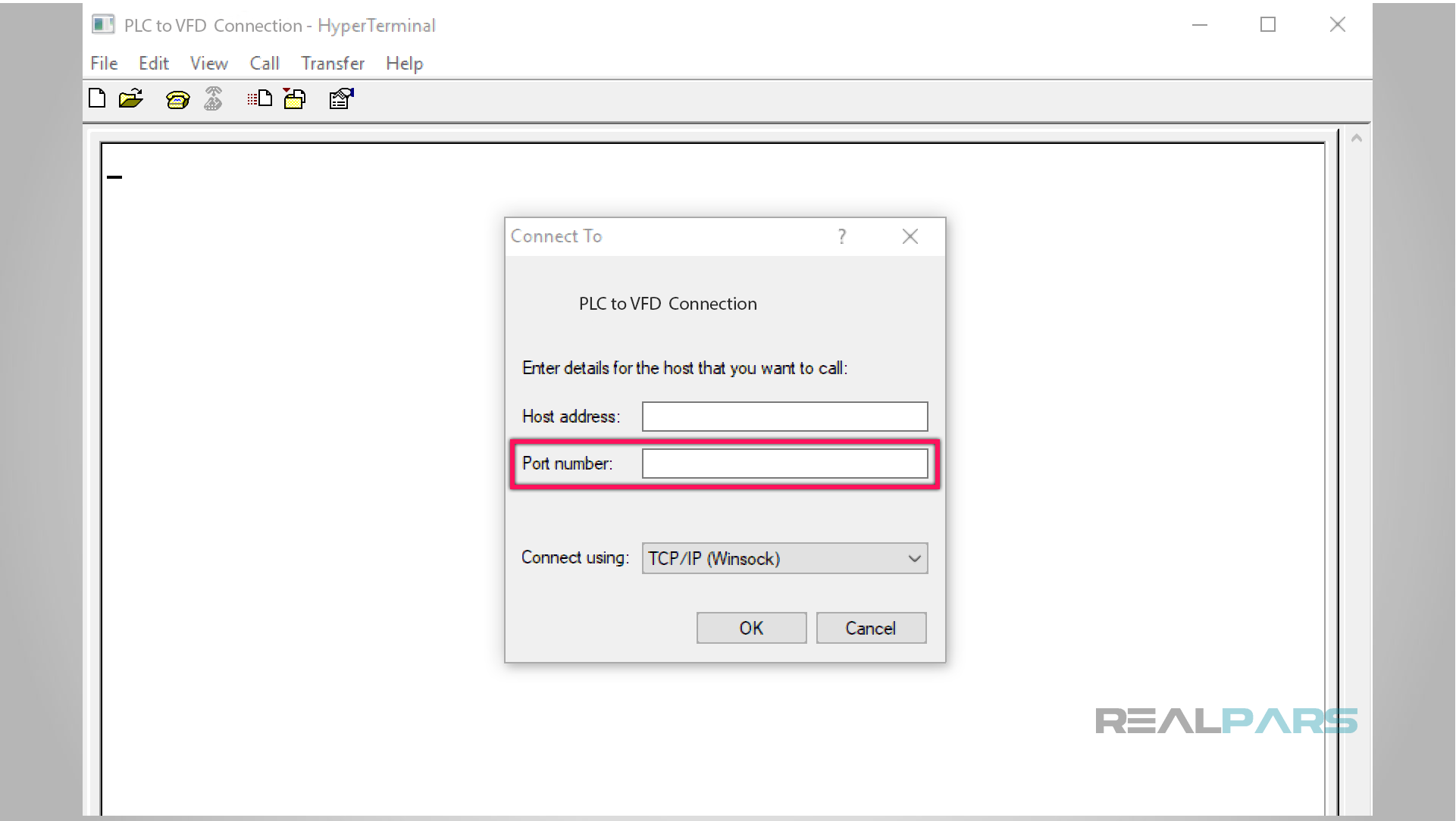
This is achieved through the Gateway Configuration Interface, which features a text-based user interface that can be accessed using standard terminal emulation software such as the “Microsoft Hyper Terminal”.
From the physical point of view, the gateway is using a standard RS232 interface.
Once connected, Start “Hyper Terminal” software and configure it to the correct physical “COM port” set up on your Laptop.
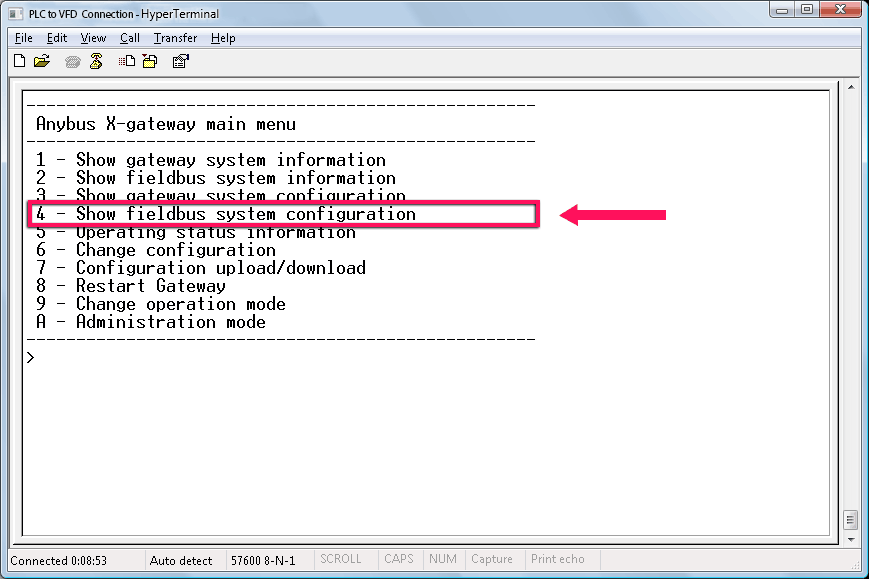
After you connected, the Main Menu will be displayed displaying multiple choices with a corresponding number.
I select number 4 from the HMS gateway menu, for the Fieldbus system configuration.
In the configuration menu, I set the I/O data size for each network.
We also instructed the HMS gateway to clear the data if and when the gateway where to go offline as a safety precaution.
This completes the HMS ControlNet slave configuration setup.
This concludes the article, How to Control a VFD with a PLC (Rockwell PLC and Gateway Communication). Stay connected with RealPars for Part 2 and Part 3 lessons.
In Part 2, we will discuss how to configure the HMS Gateway “Profibus Master” communication to the Siemens Robicon VFD.
I hope you have enjoyed learning what will support you in your upcoming project. If you would like to get additional training on a similar subject, please let us know in the comment section.
Got a friend, client, or colleague who could use some of this information? Please share this article.
The RealPars Team
How to Control a VFD with a PLC – Part 2
How to Control a VFD with a PLC – Part 3
How to Control a VFD with a PLC – Part 4
How to Control a VFD with a PLC – Part 5