

Welcome to lesson 3 of How to control a VFD with a PLC. We have created this Siemens VFD training series of lessons discussing the steps to configure and program communication between a Rockwell ControlLogix PLC and a Siemens VFD.
As a prerequisite, please take a look at Part 1 and Part 2 of this series of lessons.
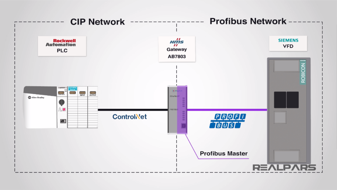
In Part 1, we have addressed how to configure the communication between ControlLogix 5000 PLC and HMS Anybus gateway using ControlNet network media with CIP protocol.
In Part 2, we discussed how the HMS gateway was set up as a PROFIBUS Master to communicate and control the slave Robicon VFD using PROFIBUS protocol.
The gateway is a device for converting or translating ControlNet CIP protocol to Siemens PROFIBUS protocol.
The scope of our work in this part, part 3, is primarily provided into setting up the Siemens VFD to complete the communication path between the gateway and the Rockwell ControlLogix processor.
Perhaps for the average learner, the overall communication configuration process to accomplish this may be somewhat complex to understand without all of the details for each of the three-interconnecting equipment (PLC, Gateway, and VFD) used.
However, our lessons have been created with this in mind, to help simplify the overall configuration by providing only the necessary steps for communication and assumes the learner has some knowledge of the process equipment used in these articles.
If you would like RealPars to provide more details on any of Rockwell processors, HMS gateway and Siemens Robicon VFD, please let us know in the comment section or contact us directly.
Overall, the ControlLogix PAC will be controlling a pump with a simple ON/OFF command and velocity by setting a speed setpoint to the VFD.
In response, the Siemens VFD will return the actual speed reference and VFD status information controlling the pump.
This exchange of control data and status information is all performed by the HMS gateway.
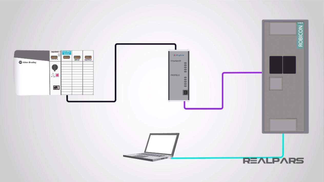
We will begin our Robicon VFD configuration by connecting a Laptop Ethernet port using a non-crossover Ethernet cable to Ethernet port on the VFD.
Ping the IP address of the Robicon VFD to ensure we are connected.
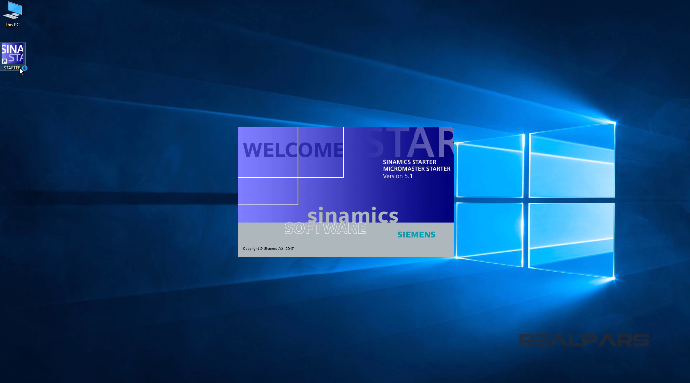
Siemens VFD Parameters Setup Using SINAMICS STARTER Software
I will start the Siemens SINAMICS STARTER program by double-clicking on its icon.
After that, a program pop-up display will open.
The STARTER Project Wizard display will appear.
Next, I select the Arrange drive units offline button.
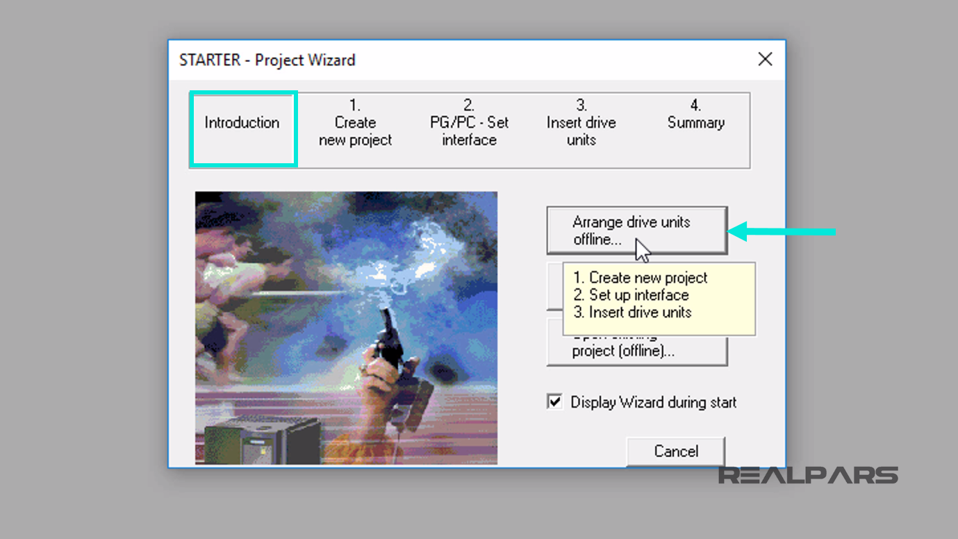
A new window will appear.
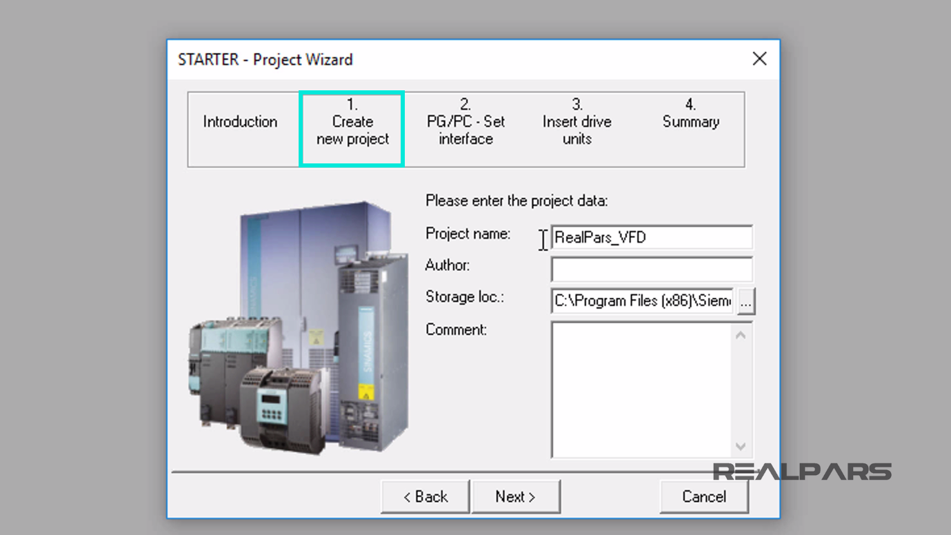
Step 1, Create new project will be highlighted.
I will enter the Project name as, RealPars_VFD. Now, let’s select the Next button.
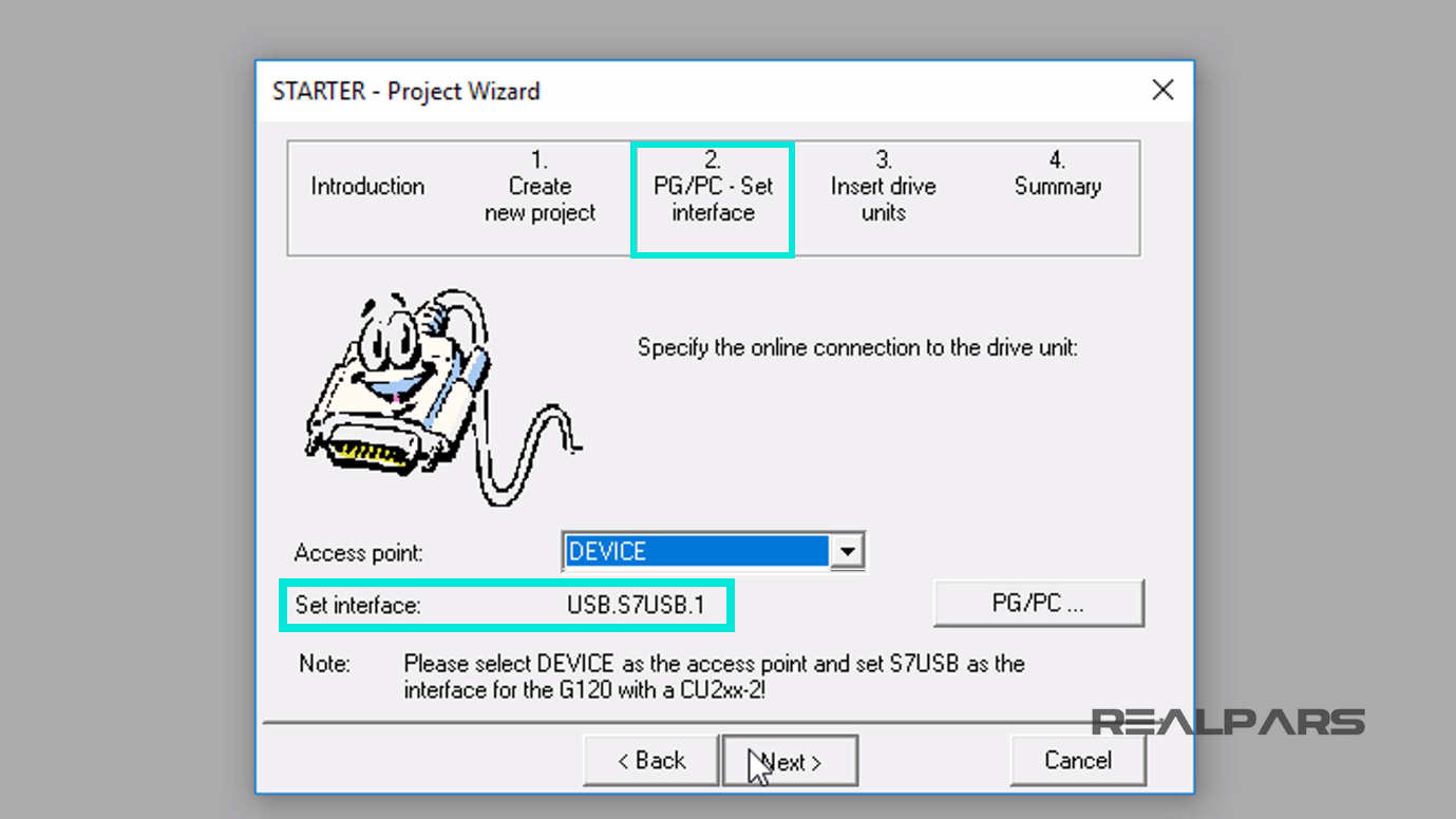
Step 2, PG/PC – set interface tab display area appears.
For the Access Point, I will select Device and the Set interface becomes, USB.S7USB.1.
Again, I select the Next button to bring up the next project configuration category.
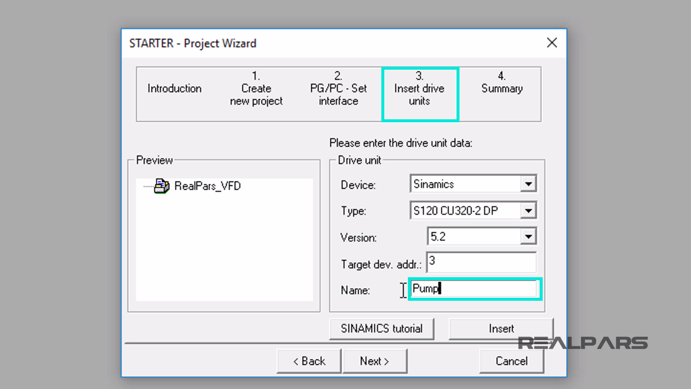
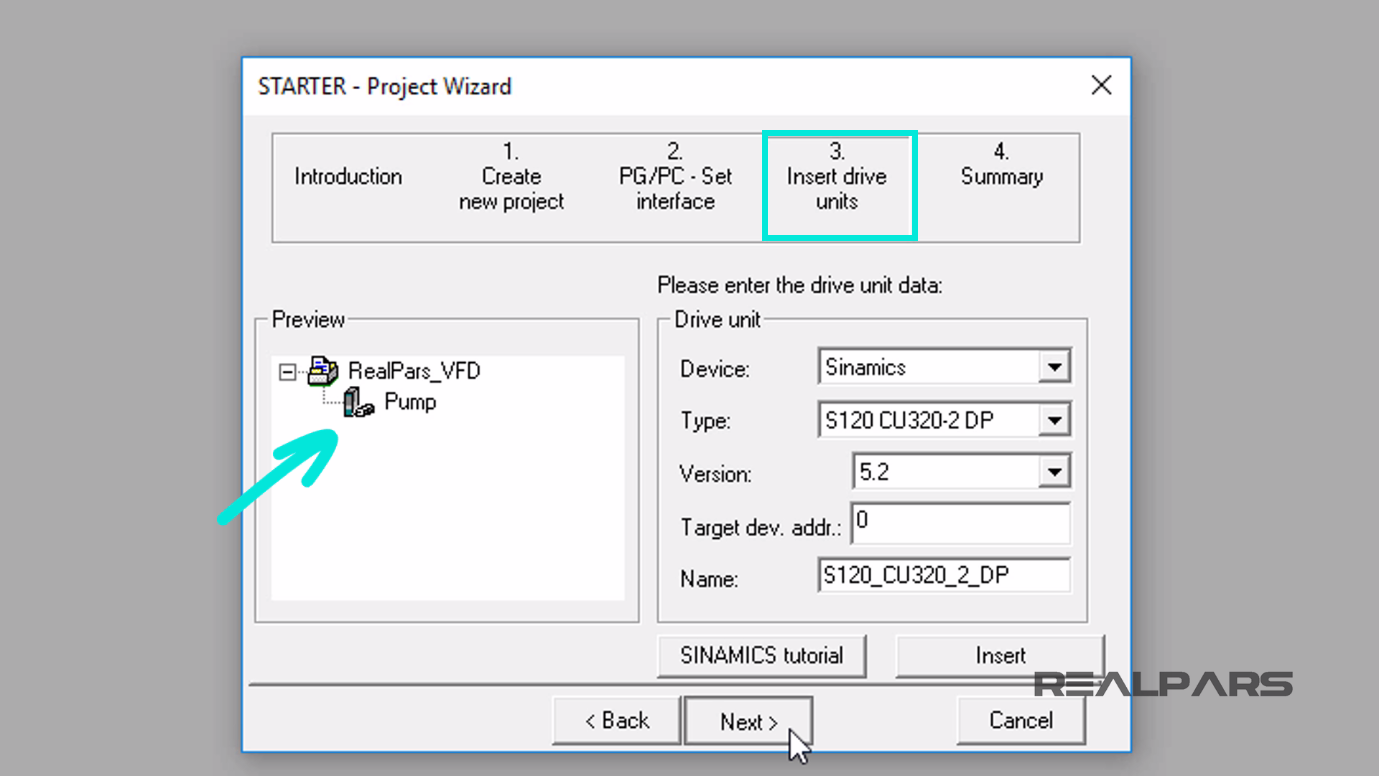
Step 3, Insert drive units display tab appears.
In this configuration display, I will select Sinamics for the Device.
For the Type, under the drop-down menu, locate S120 CU320-2 DP.
Enter 3 for the Target device address; this is the PROFIBUS device address we assigned using the HMS Gateway as the PROFIBUS master in part 2.
Also, I set the Name to Pump, since this is what the drive and motor will operate.
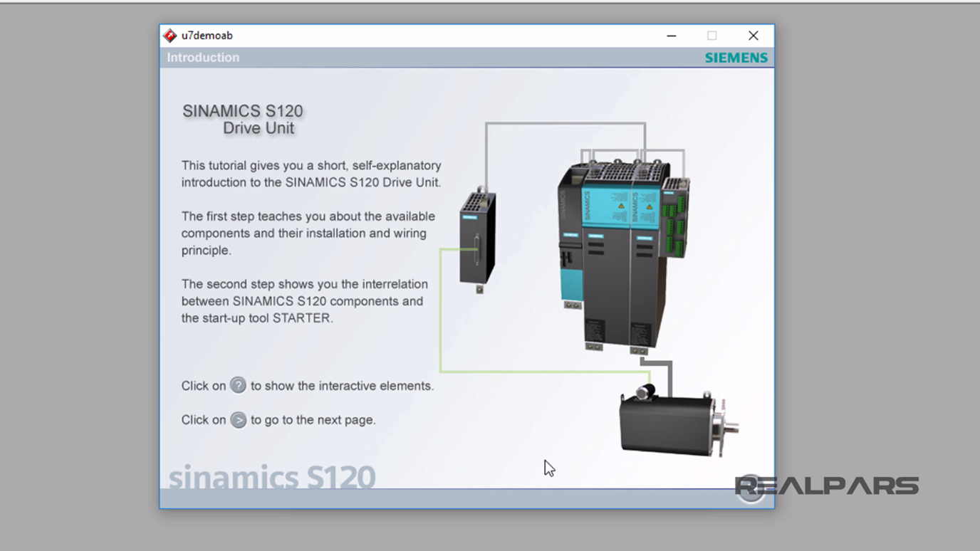
For those of you that wish to learn more about the Siemens S120 drive, you may select the SINAMICS tutorial button in the Insert drive units display tab, for further understanding of the S120.
Now, let’s select the Insert button to add the drive to the project; the S120 Pump icon will display into the Preview Window.
Then I’ll select the Next button to complete this portion of the drive configuration.
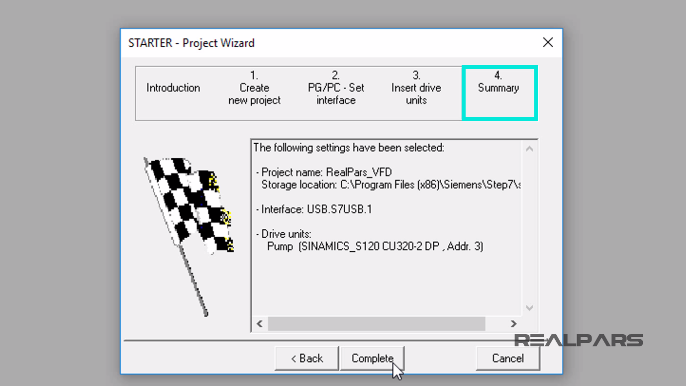
The final Summary screen will display.
To complete the wizard setup, I will press the Complete button on the Summary display tab.
After a few seconds, the STARTER RealPars_VFD project display window will appear.
Now that the drive is configured, I need to add Input/Output components and a Drive device that will be controlling the motor.
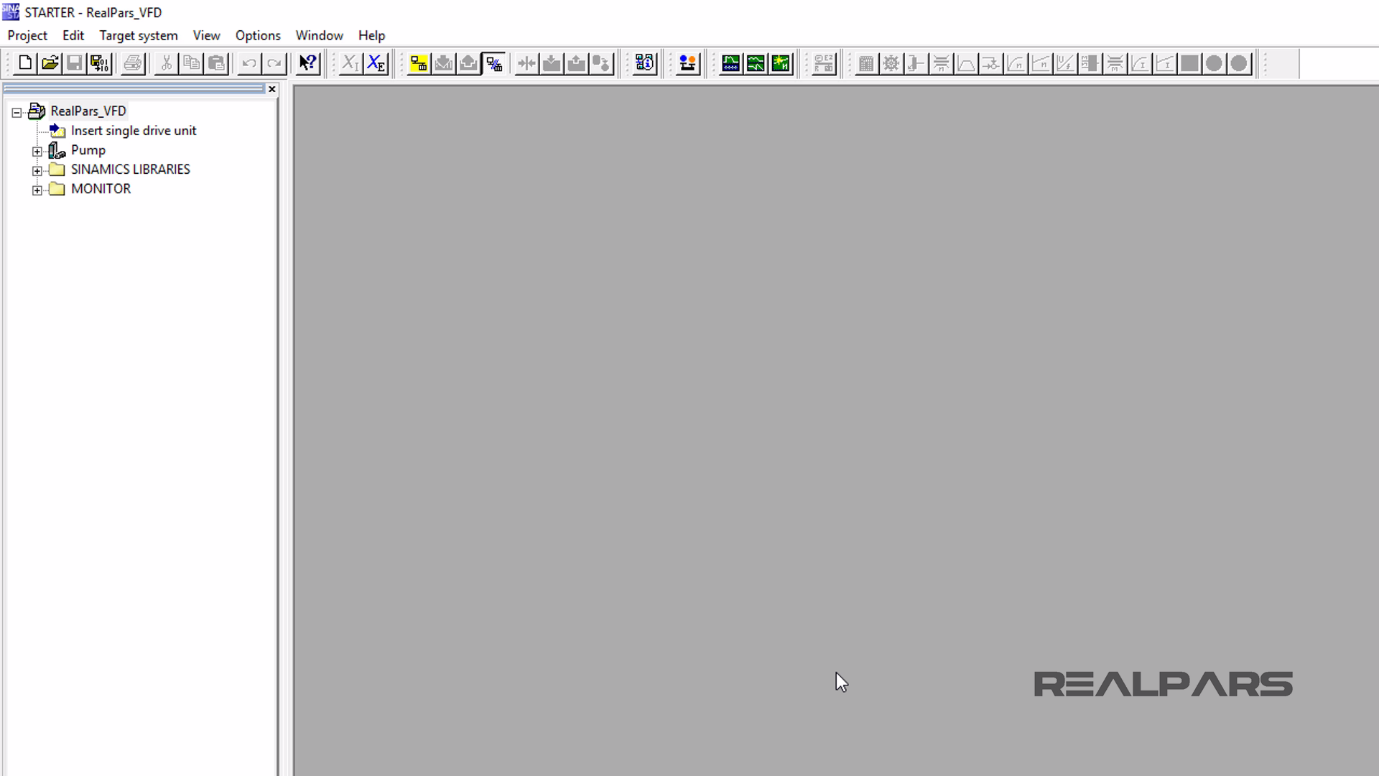
I click on the plus sign (+) next to the Pump to show the list of Pump components.
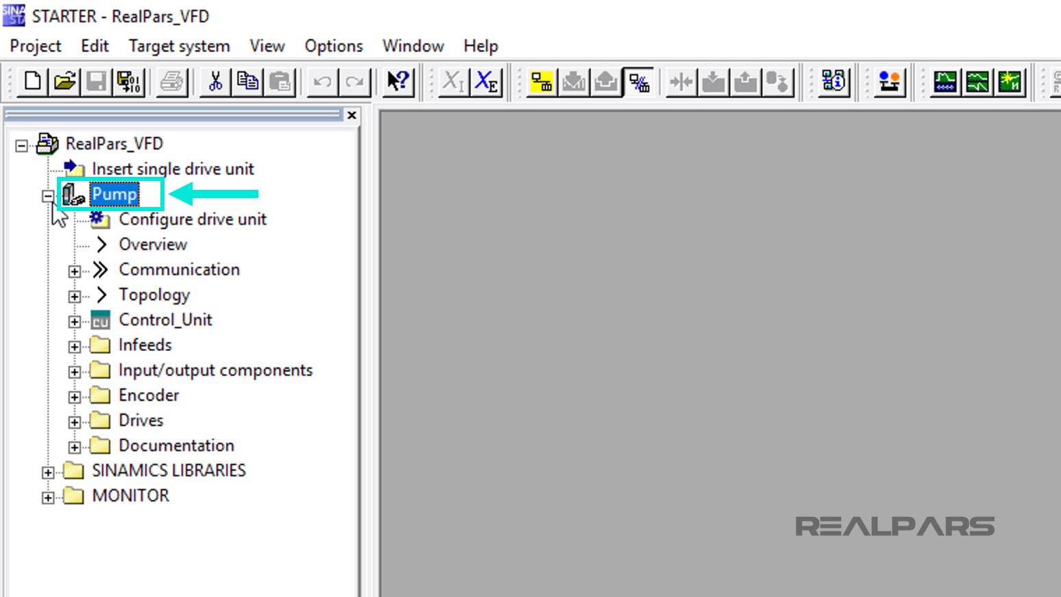
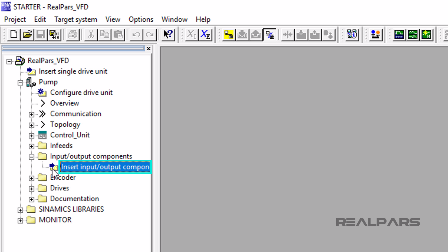
Next, I expand the Input/Output components by selecting the plus sign (+) next to the folder.
Now, I double click the Insert input/output components folder.
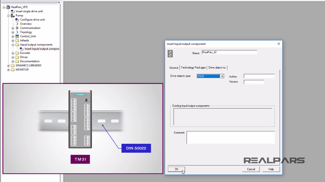
In this window, for our example, I will provide the name of RealPars_IO.
For the Drive objects type I will select TM31.
The Terminal Module 31 (TM31) is a terminal expansion board that can be attached to a DIN 50022 mounting rail. It can be used to increase the number of available digital inputs/outputs and analog inputs/outputs within a drive system.
I press OK to close this window.
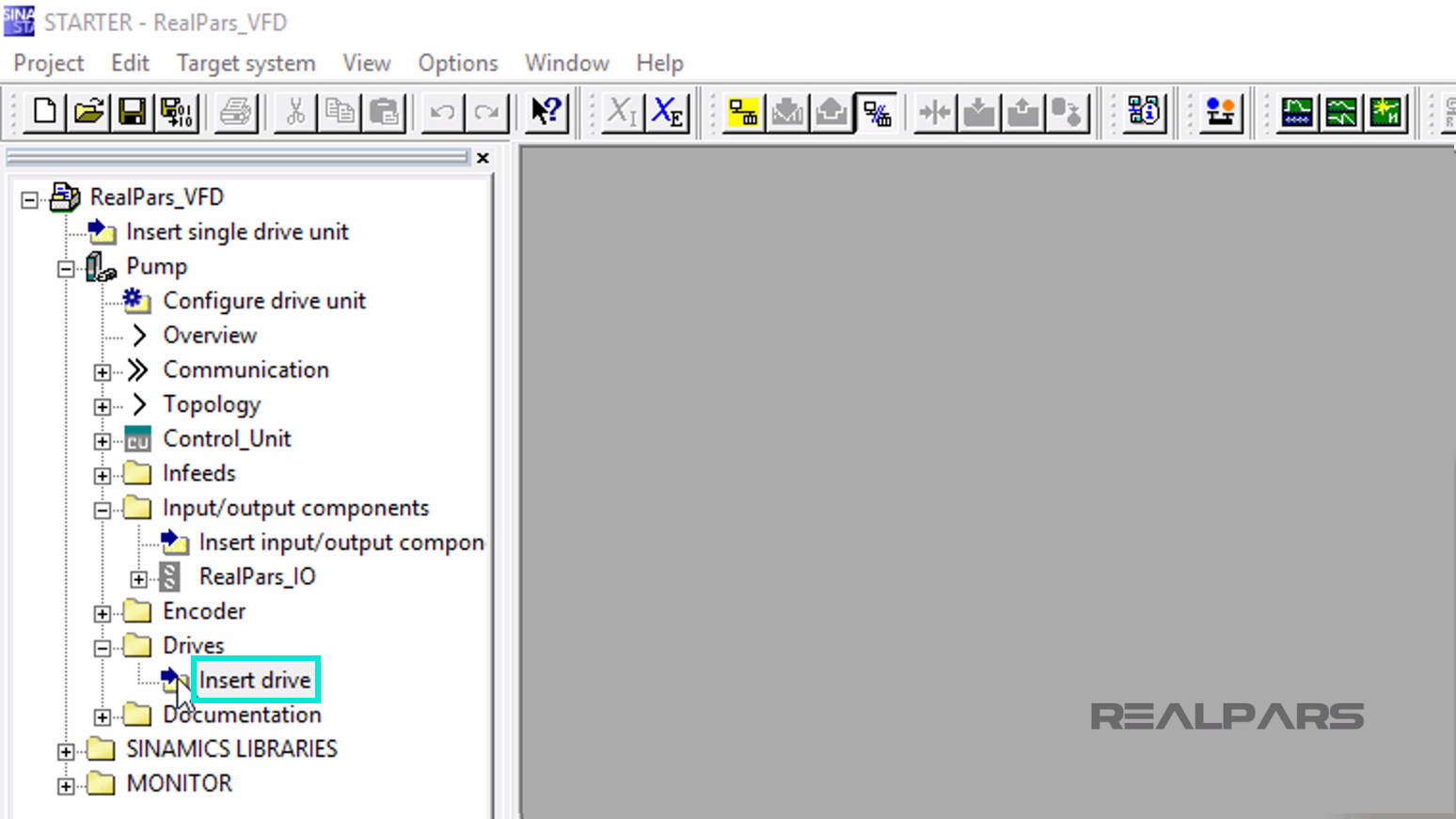
Under the Drives folder, I double click over the Insert drive folder.
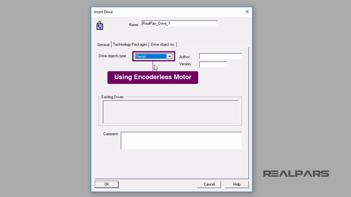
On the Insert Drive window, I enter the name RealPars_Drive_1 under the General tab.
Under the General tab, for the Drive objects type, I select the Vector.
Vector is chosen over Servo type because in this configuration the type of motor used does not use an encoder for feedback.
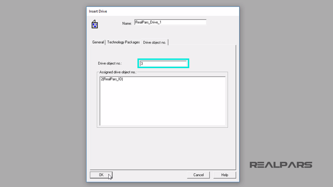
Now under the Drive object no. tab, I assign 3 to the Drive object no. because it is the next available object number. I then select OK.
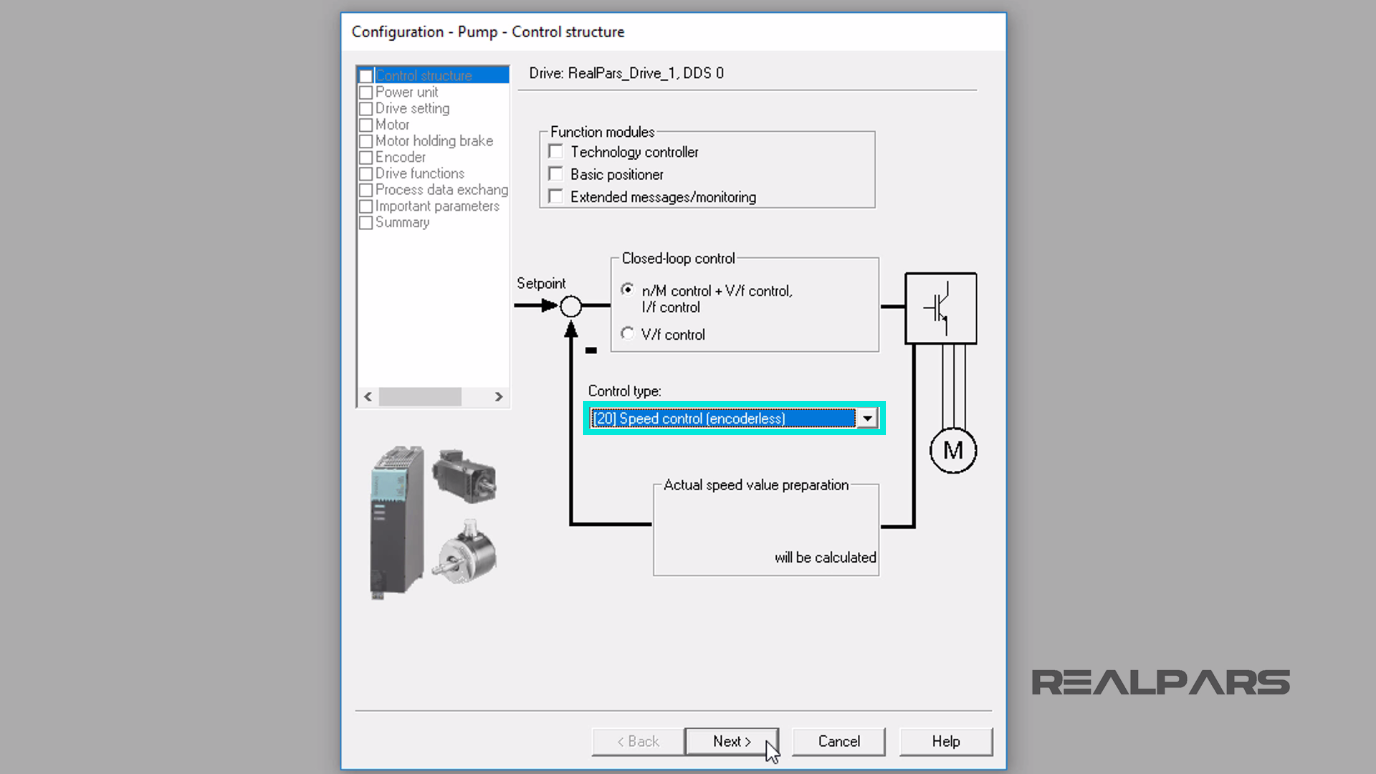
The Control structure configuration display appears.
I will select the [20] Speed control (encoderless) as the Control type. I then select the Next button.
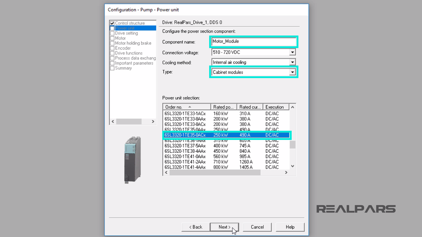
In the next display window, I will change the Component name to Motor_Module. Under the Type drop-down menu, I choose the Cabinet modules.
In the Power unit selection area, we will match the power unit installed and then navigate down to locate the 6SL3320-1TE35-0ACx power unit.
I leave the other fields as they are and then press the Next button.
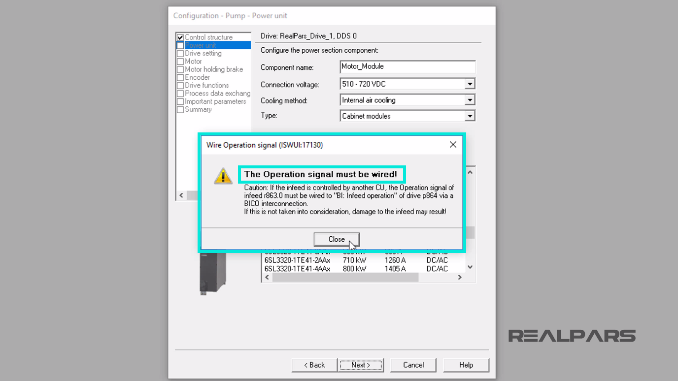
When I press the Next button in the previous window, Wire Operation signal Warning may appear and indicate a Caution that The Operation signal must be wired!.
I will ignore this and click Close and continue to the next stage.
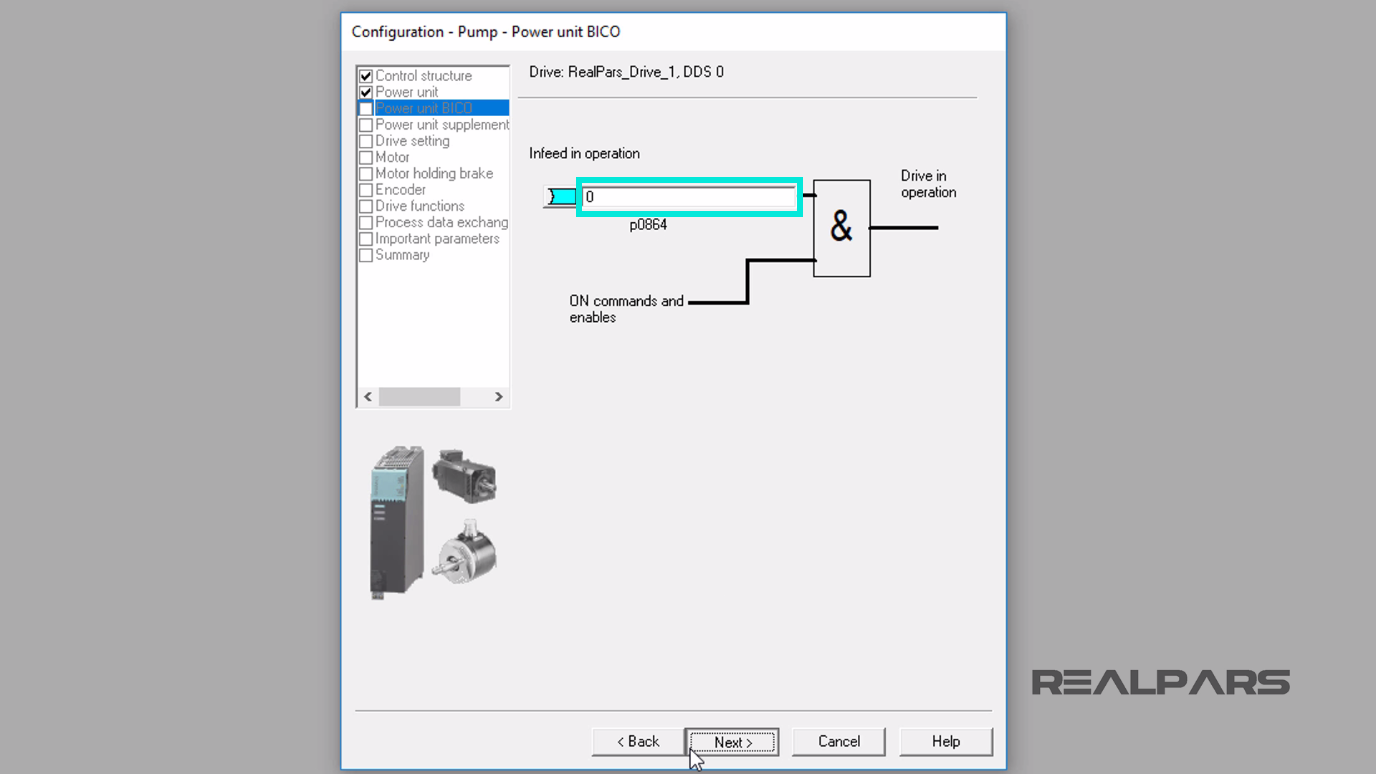
In this window, we will leave the Infeed in Operation set to 0 because the Ready signal for the infeed is issued by an outside control unit.
To continue, I will press the Next Button.
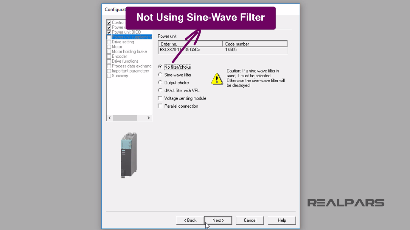
I will leave No filter/choke selected because we will not use a sinewave filter. To continue, I select the Next button.
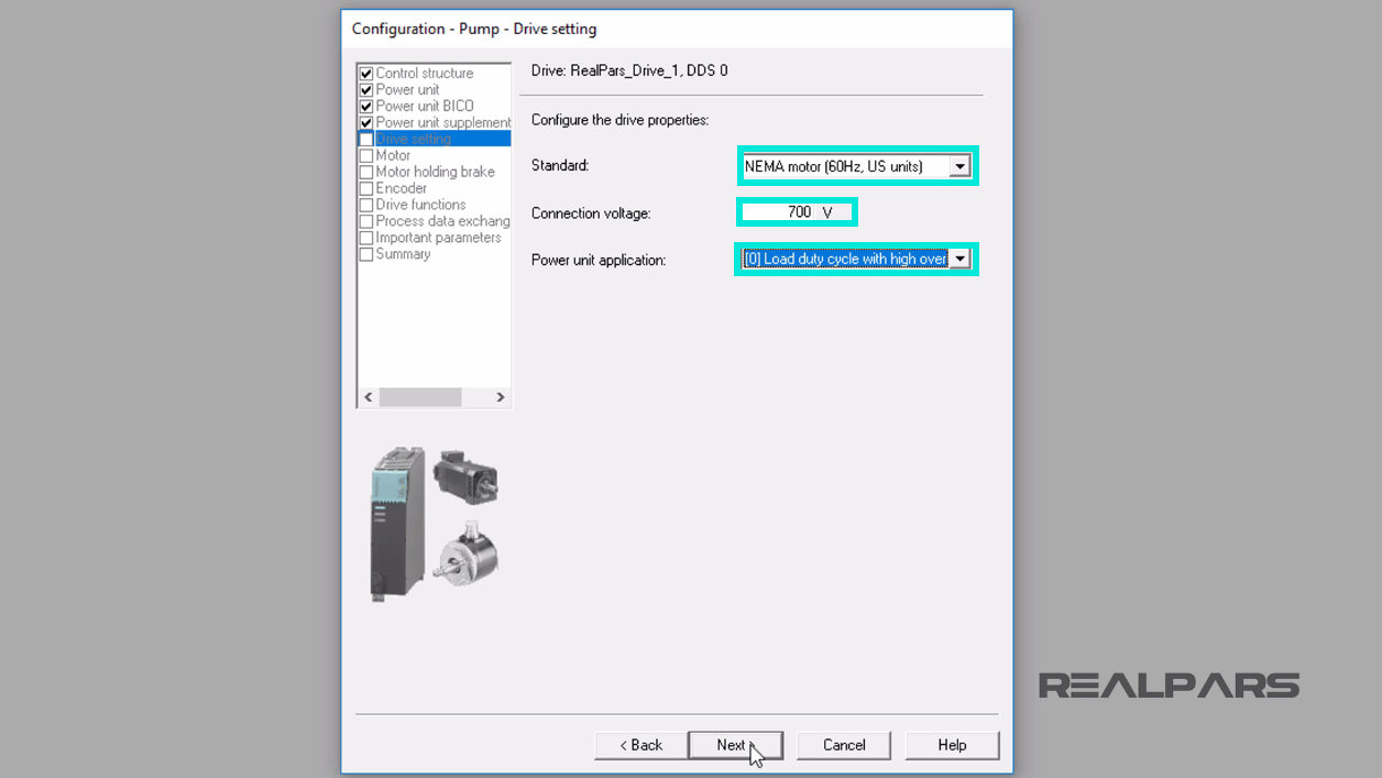
On the Configure the Drive properties display I will select the NEMA motor (60 hertz, US units), and next, I set the Connection Voltage to 700 volts.
For the Power unit application, I will choose Load duty cycle with high overload.
High overload is chosen because the base load current for a slight overload is based on a load cycle of 110% for 60 seconds or 150% for 10 seconds and the base load current for a high overload is based on a load cycle of 150% for 60 seconds or 160% for 10 seconds.
I will select the Next button.
For now, we will stop with this segment of the lesson, configuring the RealPars VFD using Siemens STARTER software.
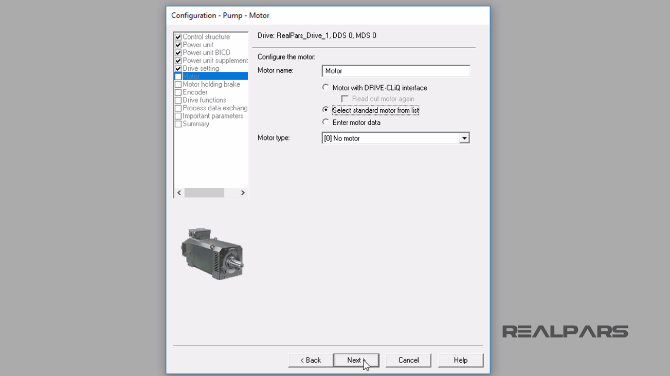
In the next lesson, Part 4 and the final part of these articles, we will continue with the VFD configuration and jump into configuring the type of motor and its nameplate data.
This concludes this part of the lesson, ControlLogix PLC and Siemens VFD Communication Part 3. So the remaining VFD configuration will be offered in Part 4 of this article series.
I hope you have enjoyed learning what will support you in your upcoming project. If you would like to get additional training on a similar subject, please let us know in the comment section.
Please check back with us soon for more automation control topics.
Got a friend, client, or colleague who could use some of this information? Please share this article.
The RealPars Team
How to Control a VFD with a PLC – Part 1
How to Control a VFD with a PLC – Part 2
How to Control a VFD with a PLC – Part 4
How to Control a VFD with a PLC – Part 5