

This is the fourth of a series of articles about the Phoenix PLCnext Starterkit. If you are interested in a powerful but inexpensive PLC, you might want to consider the PLCnext Starterkit. In this article, we’re going to show you how to create a simple PLCnext ladder logic program, download and test it on the PLCnext Starterkit.
Before we begin, we are going to assume that you have completed all of the preliminary steps we showed you in articles 2 and 3 of this series.
You need to make sure that:
– A New Project has been created
– Ethernet communication between the Starterkit and the laptop/PC has been established
– All I/Os have been correctly configured on the PLCnext Starterkit I/O
1) Create a simple ladder logic program
1-1. Create a new project
First of all, start PLCnext Engineer and open the New Project that has the Starterkit I/O configured. If you didn’t create or save a version of the New Project, no problem… Go ahead and create the New Project now… or… If you don’t remember how, read part 2 of this series.
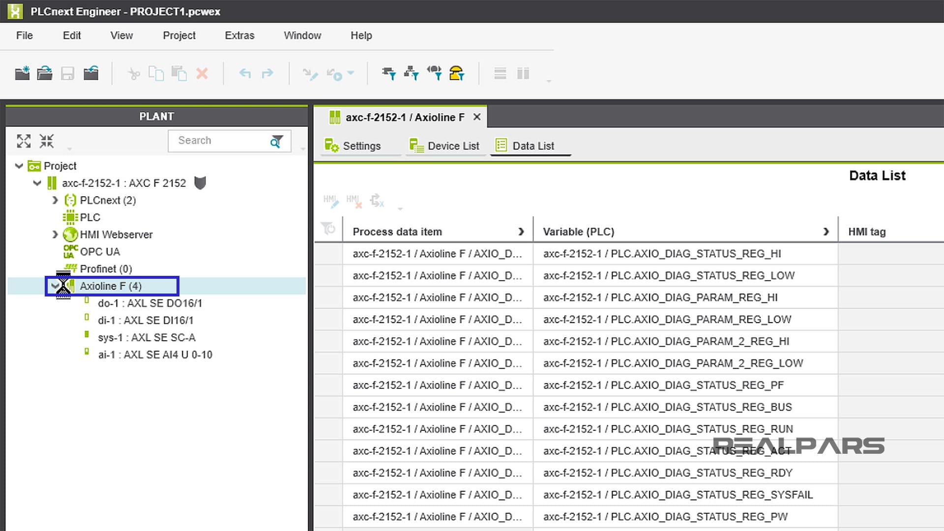
As a reminder, double-clicking on Axioline F (4) will show you details about your configured I/O modules.
1-2. Configured I/O modules
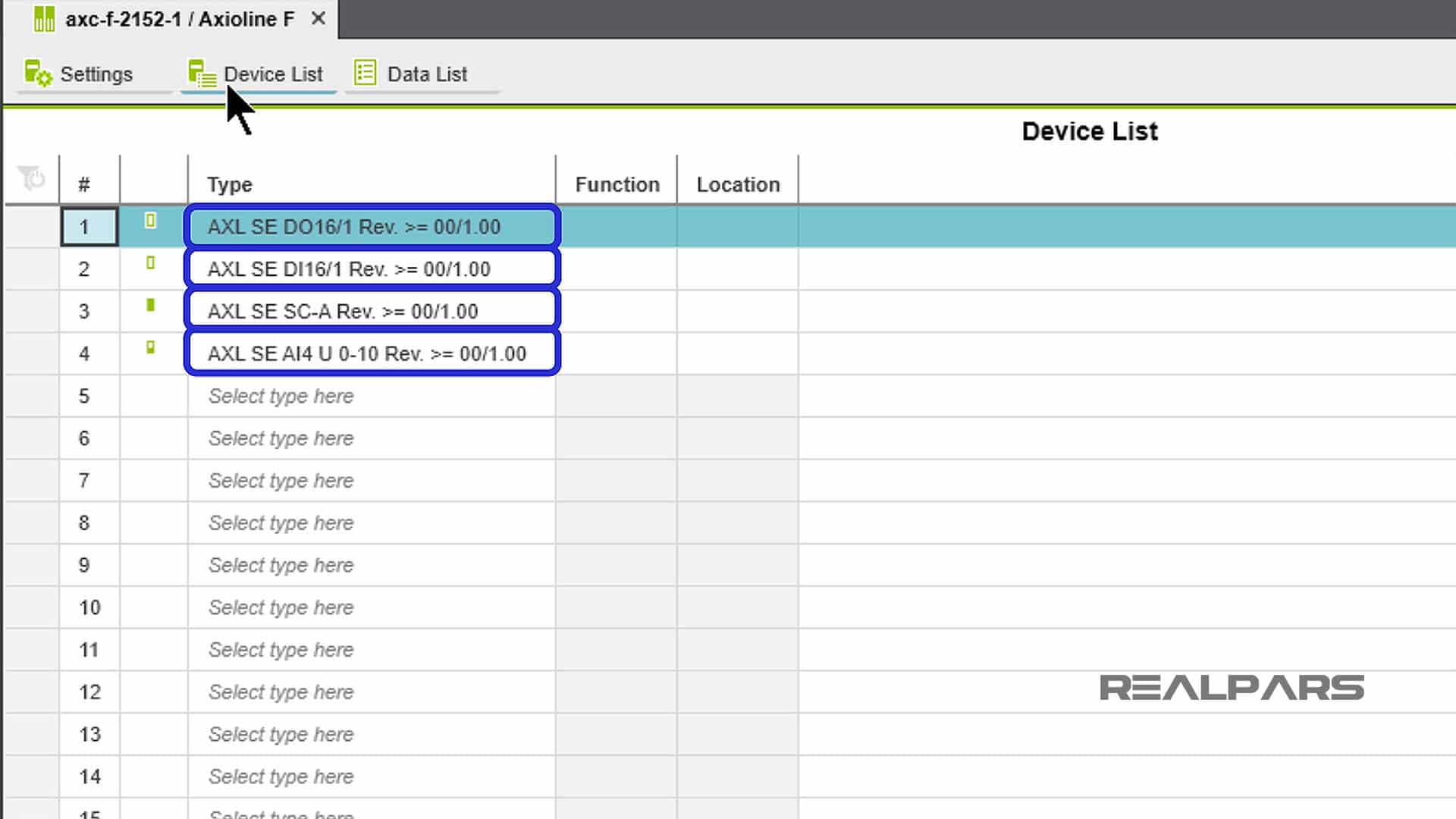
From the top menu bar, click on Device List and you will see the PLC Slot numbers in the # column and the I/O modules in each slot under the Types column.
1-3. Create ladder logic sheet
Alright, now that we’ve got a New Project with configured I/O, let’s start creating a ladder logic program!
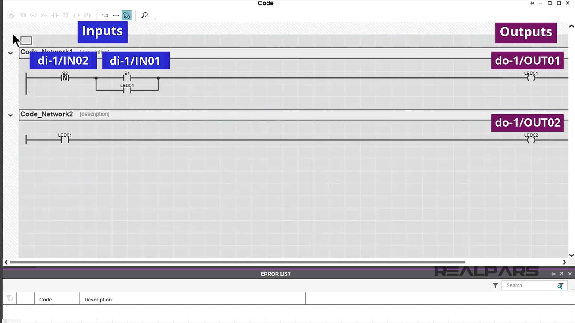
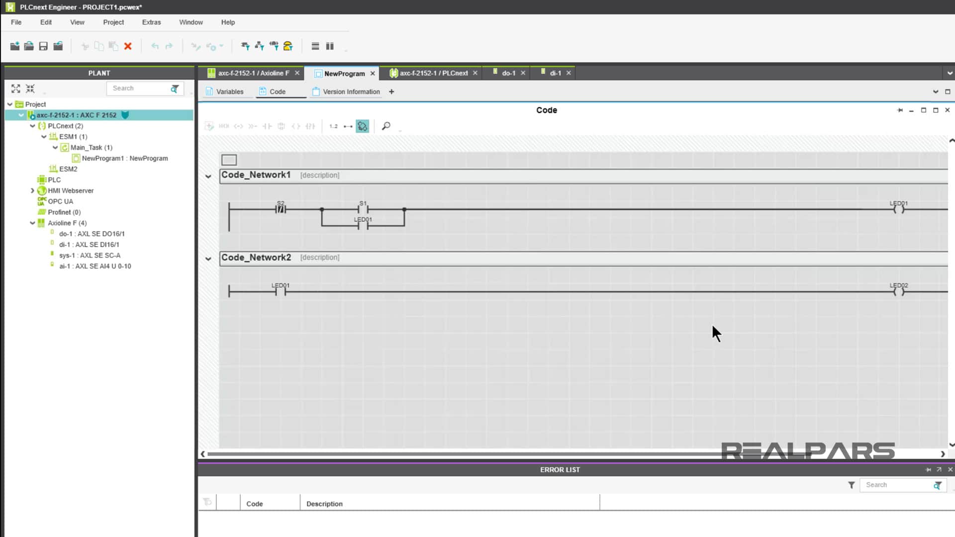
Just as a peek ahead… this is the program we are going to create. We’ve got two inputs and two outputs. We will use S1 and S2 on the Starterkit as the inputs, and the LED indicators on the Digital Output Module as outputs.
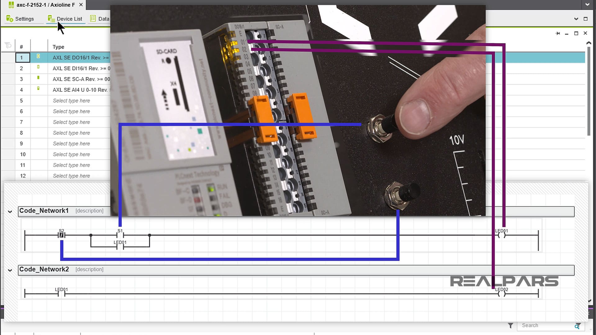
Here’s how it works…
We need to tell PLCnext Engineer that we want to start a new program using Ladder Logic.
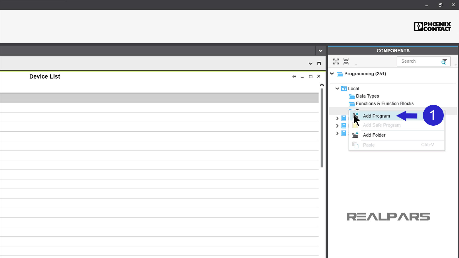
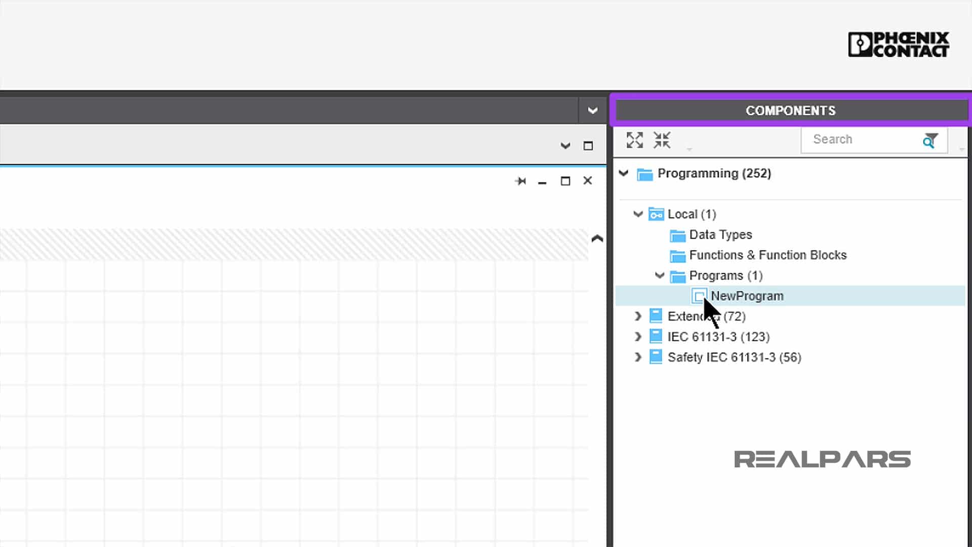
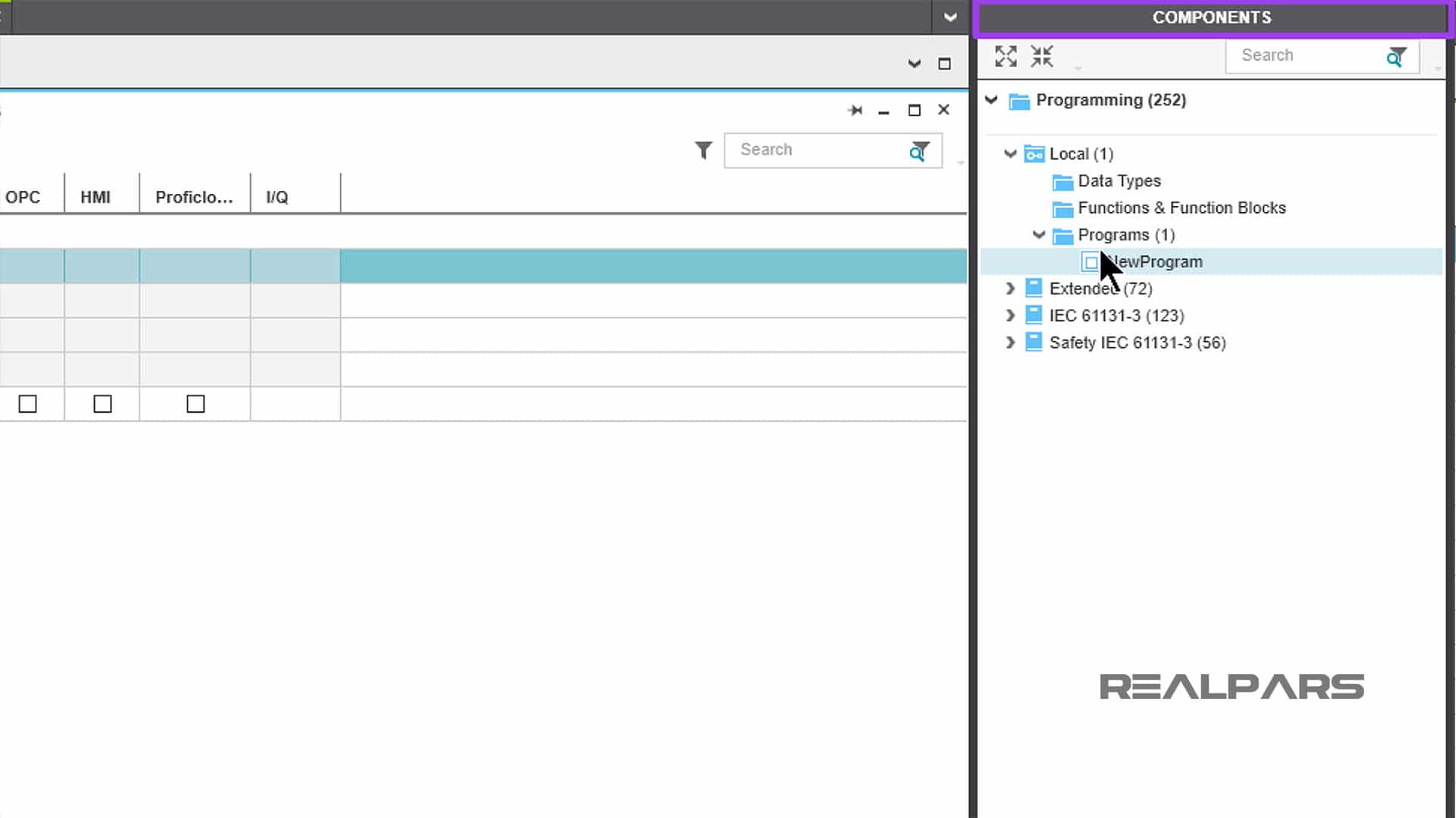
Under the COMPONENTS column, Right-click on Programs, then choose Add Program.
The Default name for your program is NewProgram. That name can be changed at any time.
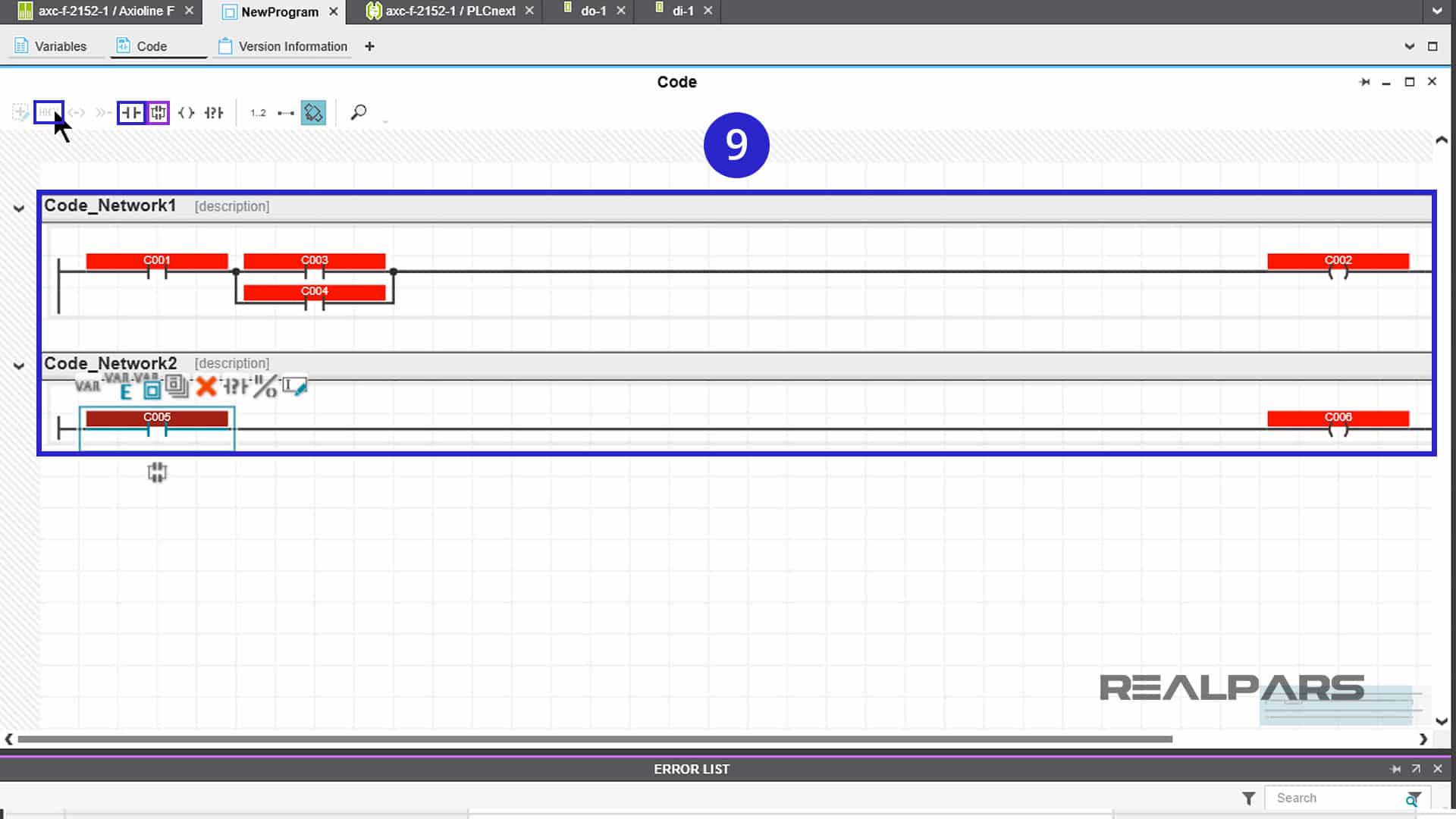
Double-click on NewProgram and choose the ladder logic program Network (1).
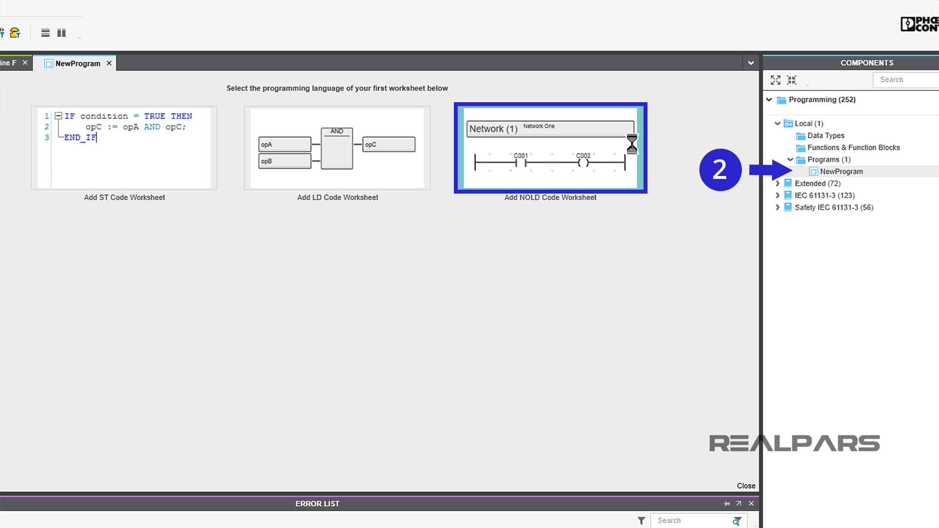
A clear ladder logic sheet will open under the header Code.
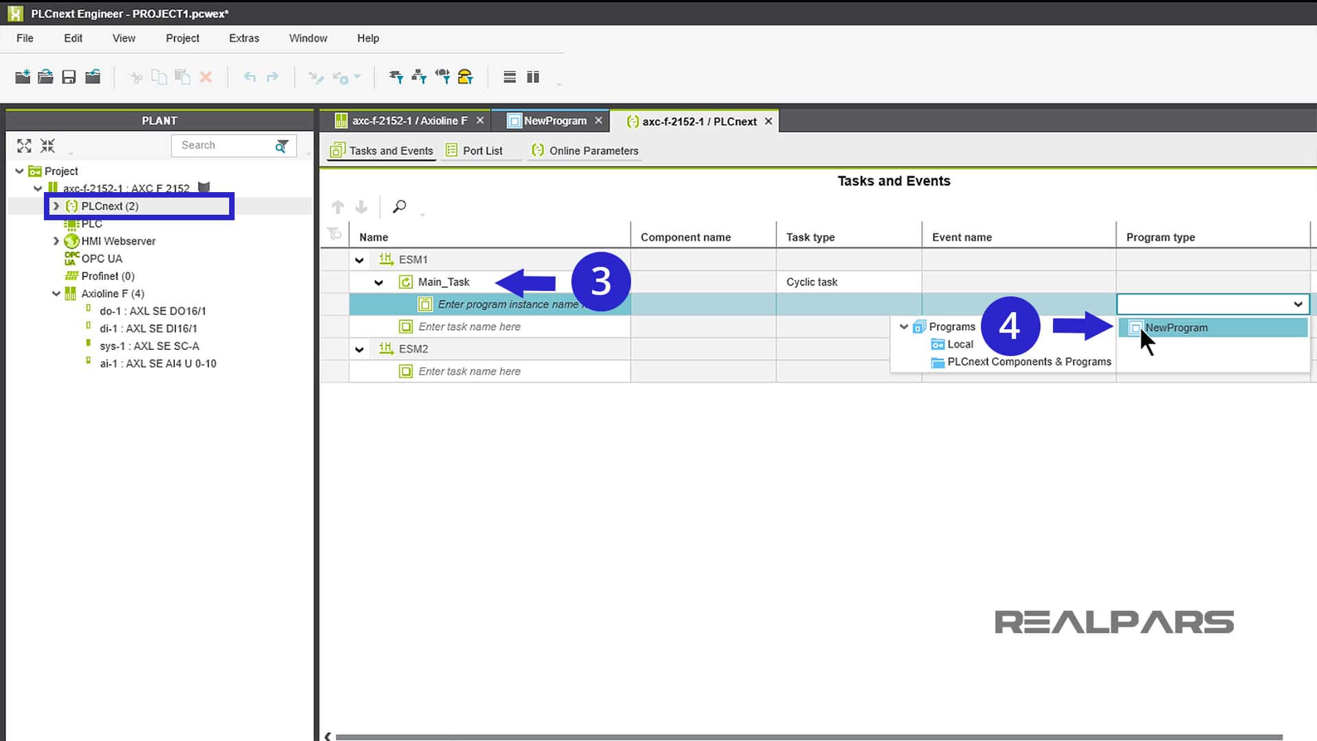
Now we need to associate our NewProgram with the PLCnext Plant. Double-click on PLCnext (2) under the PLANT column.
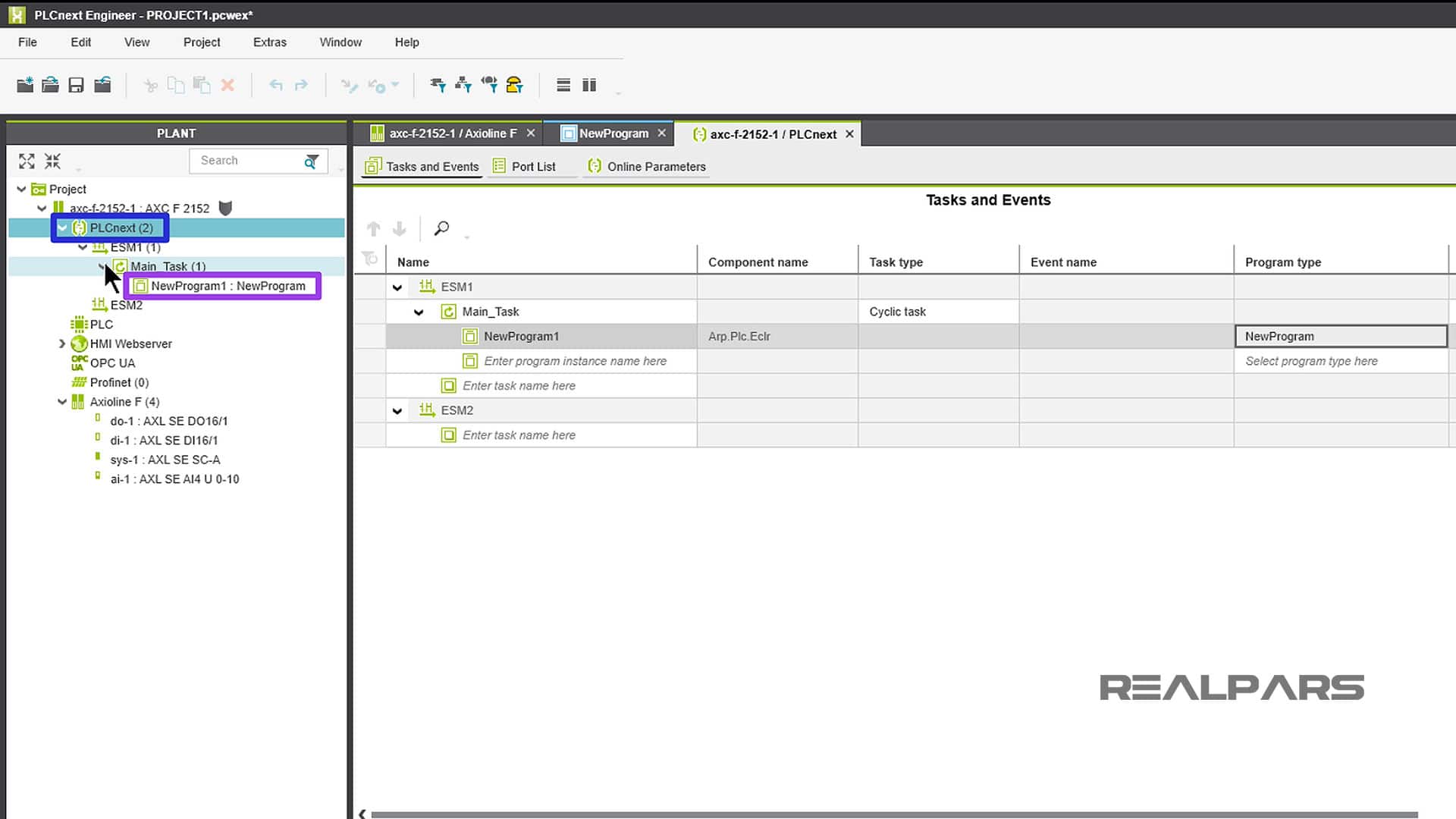
Under ESM1(1), enter the task name Main_Task. Click Select Program type here and choose NewProgram from the drop-down window.
As you drill down in PLANT, you will see your newly created NewProgram under PLCnext (2).
1-4. Create the PLC Tags
PLCnext Engineer programs are developed using variables assigned to I/O modules instead of directly addressing inputs/outputs. Many PLC vendors do the same as PLCnext Engineer and refer to these variables as Tags.
S1 and S2 are our input variables. LED01 and LED02 are our output variables. Let’s create them.
If your ladder logic worksheet is not on the screen, double-click on NewProgram under the COMPONENTS area.
From the current worksheet, click on Variables. Create all four of your BOOL variables. Be sure to select External usage for each variable.
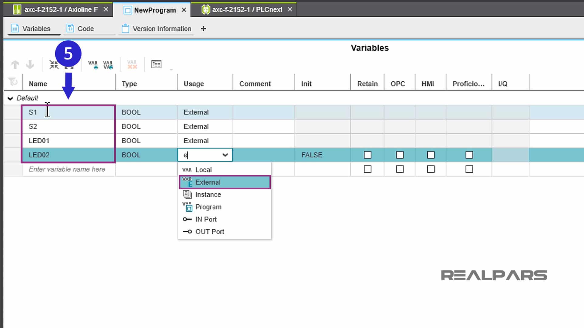
That allows you to assign each of these variables to the External I/O modules on the Starterkit.
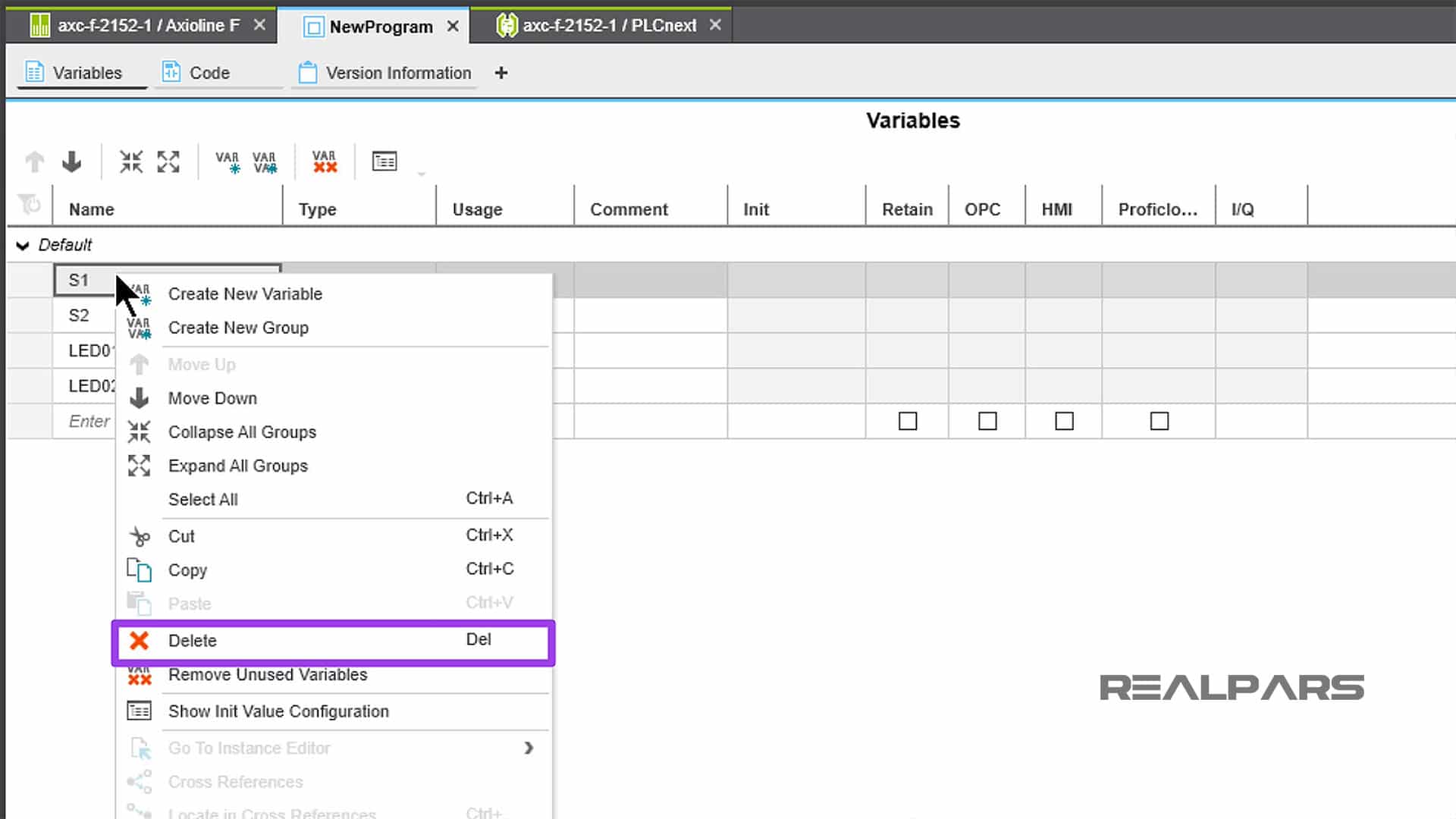
If you make a mistake or decide to delete one of your created variables, just right-click on it and select Delete from the dropdown menu.
Once the variables have been created, they need to be assigned to specific I/O modules.
So… let’s do that…
We’ve got four variables to create and assign.
– S1 and S2 are inputs and will be assigned to the Digital input (di) module
– LED01 and LED02 are outputs and will be assigned to the Digital output (do) module
Double-clicking on do-1, and di-1 under Axioline F (4) will open windows allowing you to assign the variables to respective I/O modules.
Note that di-1 and do-1 now appear as icons at the top of the screen.
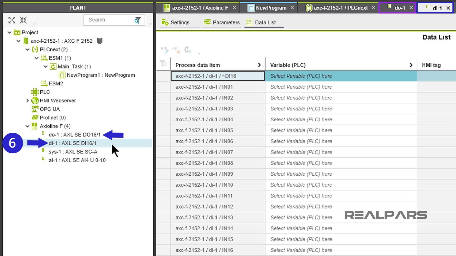
Let’s start with the inputs S1 and S2 that will be assigned to the input module in Slot 2. Choose Data List under the di-1 icon. All sixteen unassigned inputs will be shown.
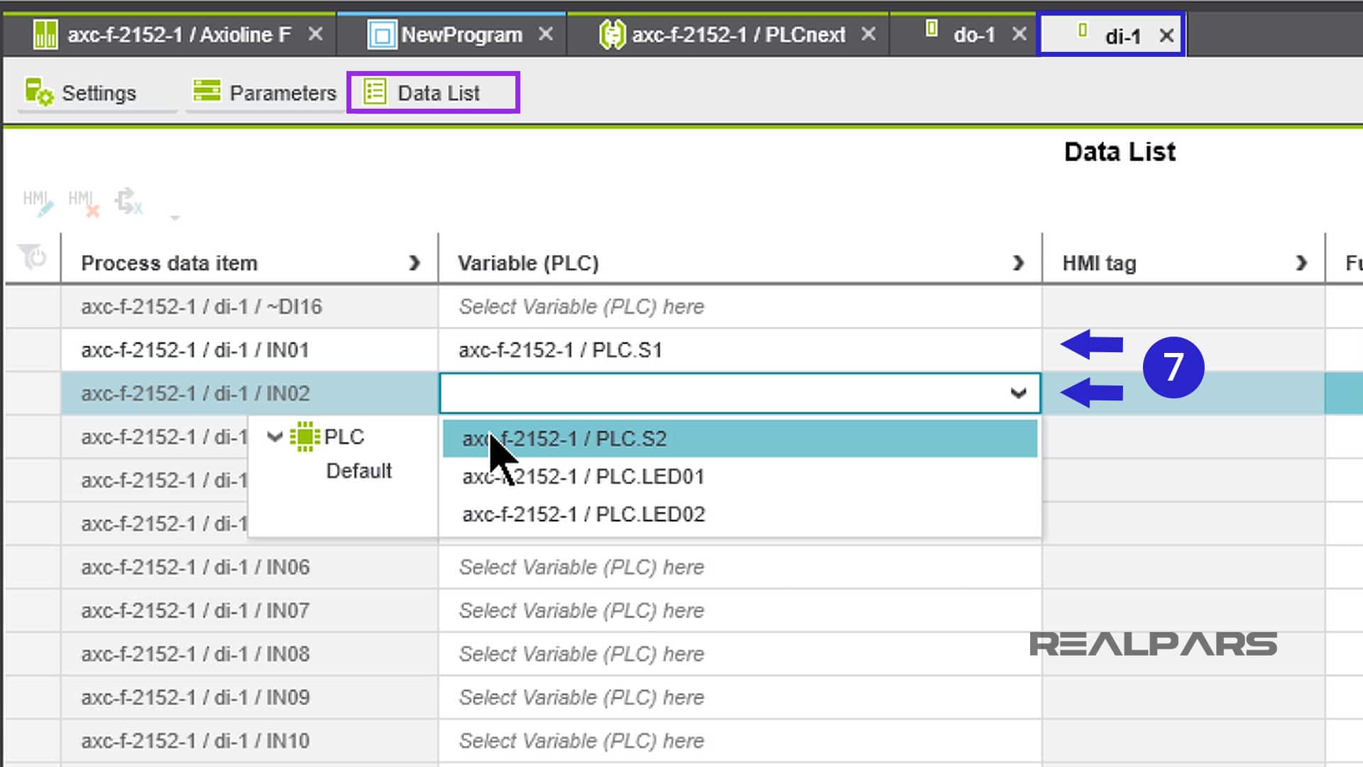
We will assign S1 and S2 to Input 01 and Input 02 respectively.
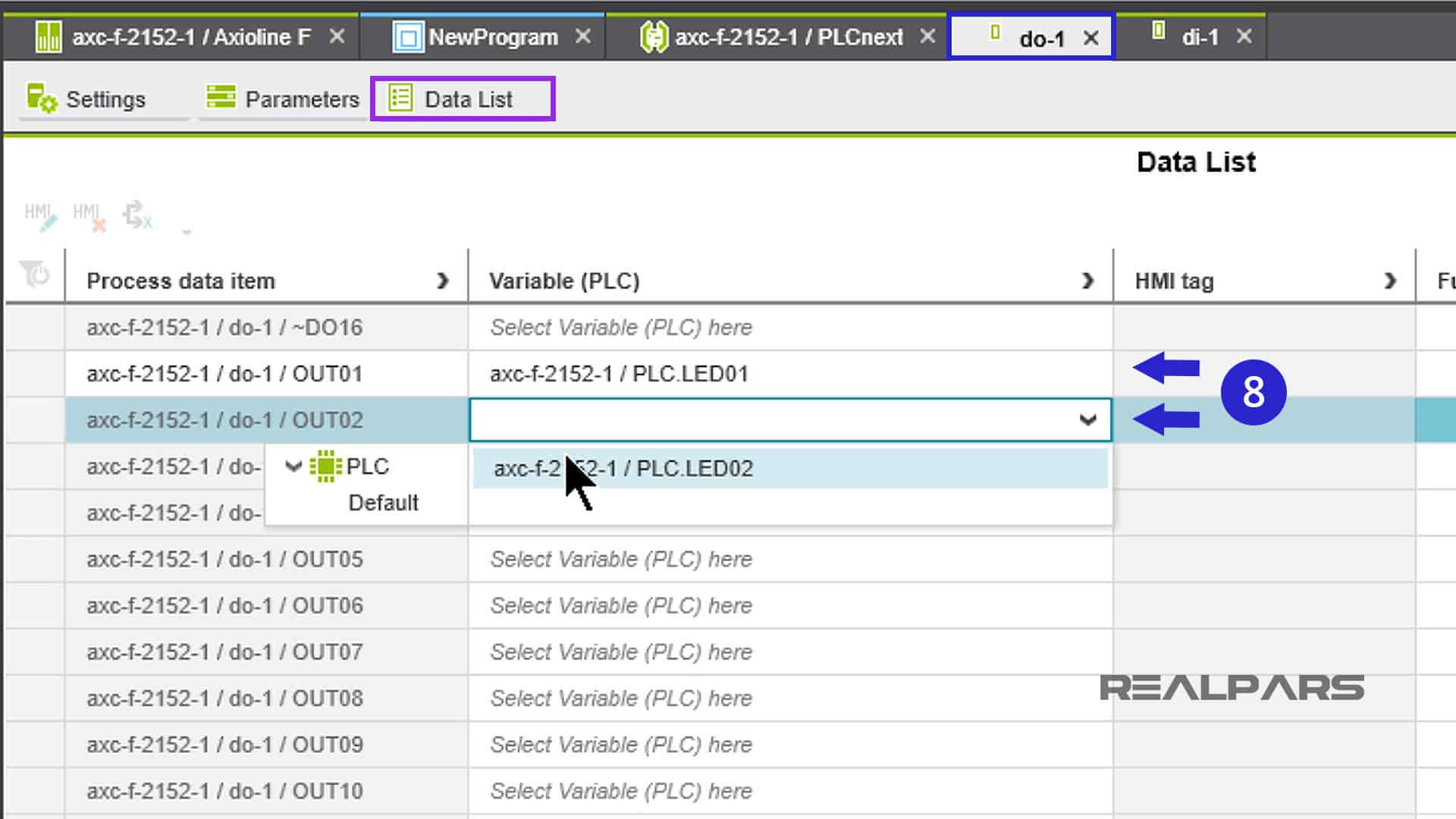
We will repeat the process for the outputs LED01 and LED02 and assign them to the output module in Sot 1.
1-5. Start writing the PLC program
Ok… now that we’ve got our variables assigned to our I/O modules, let’s start programming in ladder logic.
Go back to the blank worksheet by clicking on NewProgram under the COMPONENTS column.
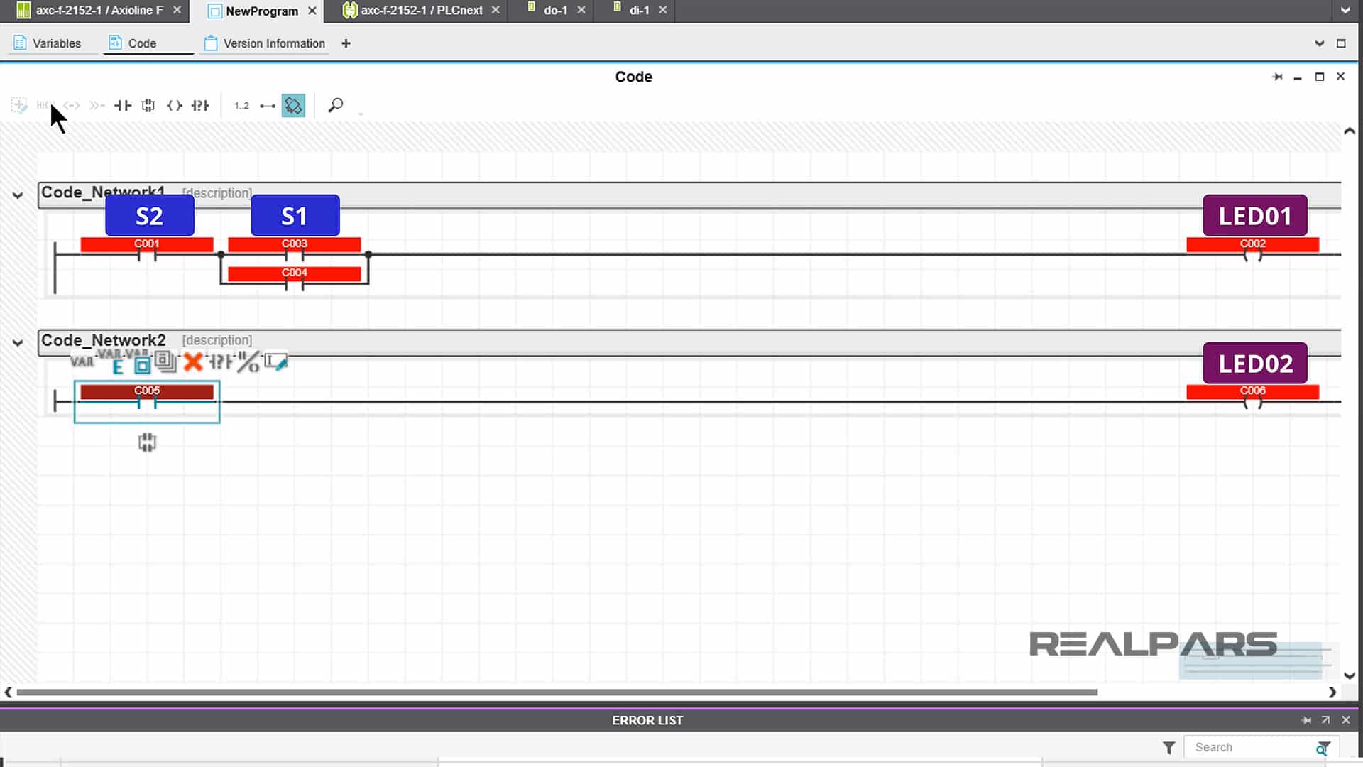
There are several ways to build the program. Once you become familiar with PLCnext Engineer, you will likely develop your own preferred method.
As you build your program, you will notice that PLCnext Engineer automatically assigns variables to each ladder logic instruction. That’s ok… don’t worry about that now because we’re going to make changes.
This would be a good time to practice with the Ladder Logic menus. Go ahead and spend some time creating and editing populated rungs in your program.
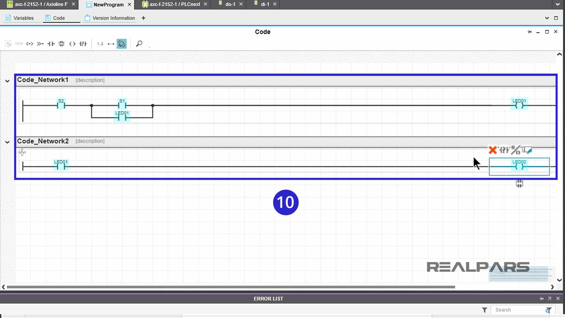
Ok… Once your two-rung program is complete and saved, we need to proceed with changing the automatically assigned variables to S1, S2, LED01, and LED02, that are those you have created.
Double-clicking on the automatically assigned variable will open a dropdown window. Scanning through the dropdown window will take you to your created variables. For each of the automatically assigned variables, proceed with tagging each of the automatically assigned variables with your created variable names.
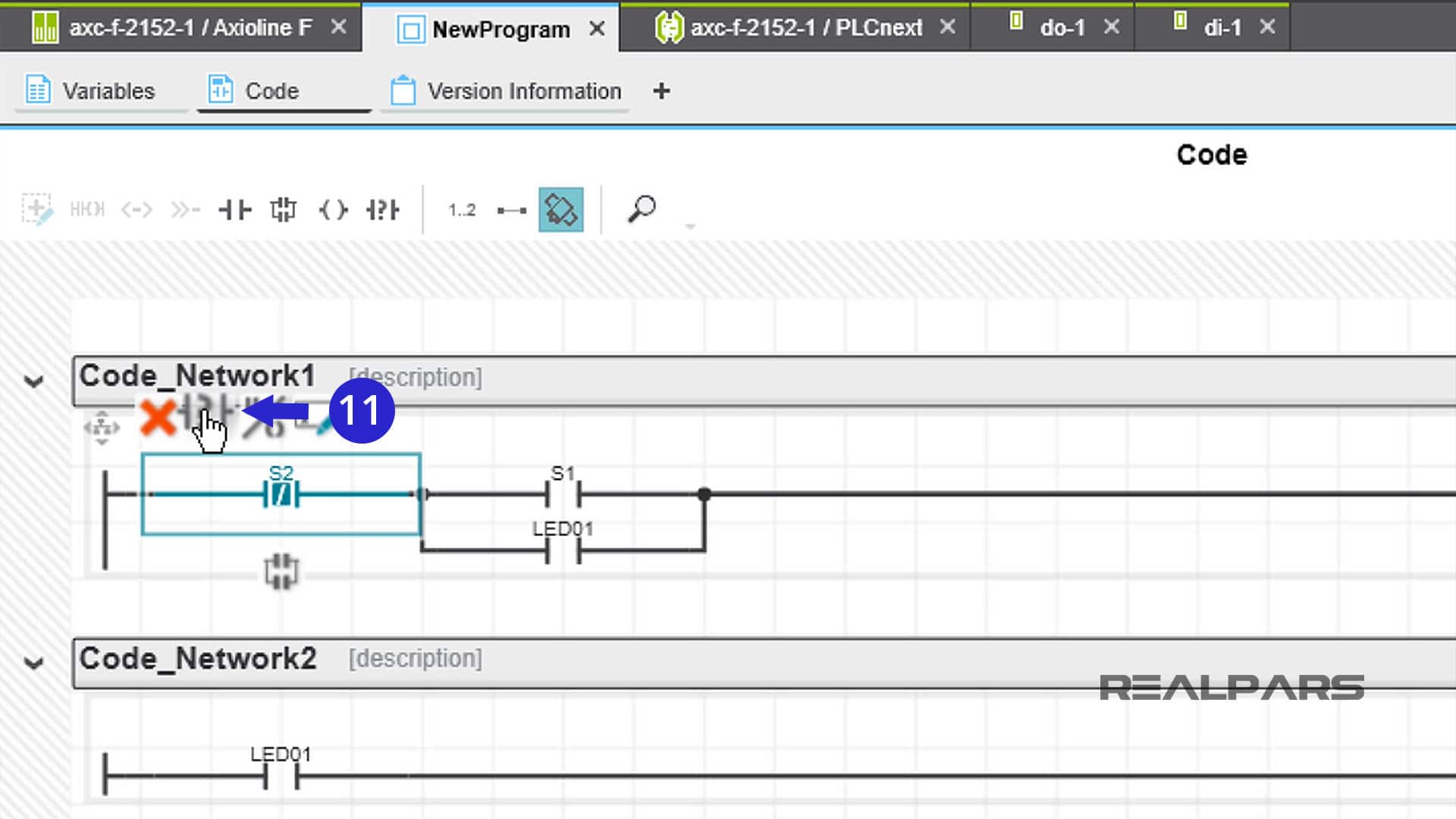
Don’t forget to change S2 to a normally closed symbol! This can be done in a number of ways.
2) Download and test the program
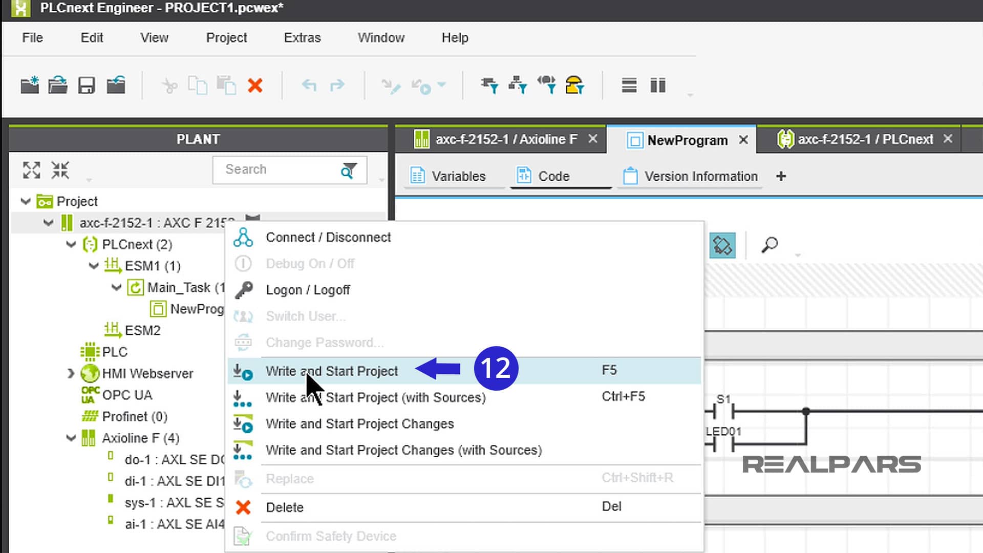
2-1. Write and Start Project
Alright… we’ve constructed the ladder logic program, now let’s download it to the Starterkit PLC and test it.
Right-click on AXC F 2152 under the PLANT column. From the dropdown menu, choose Write and Start Project.
2-2. Enter the LOGIN screen
There are a number of possible instances where you might see the SECURE DEVICE LOGIN screen.
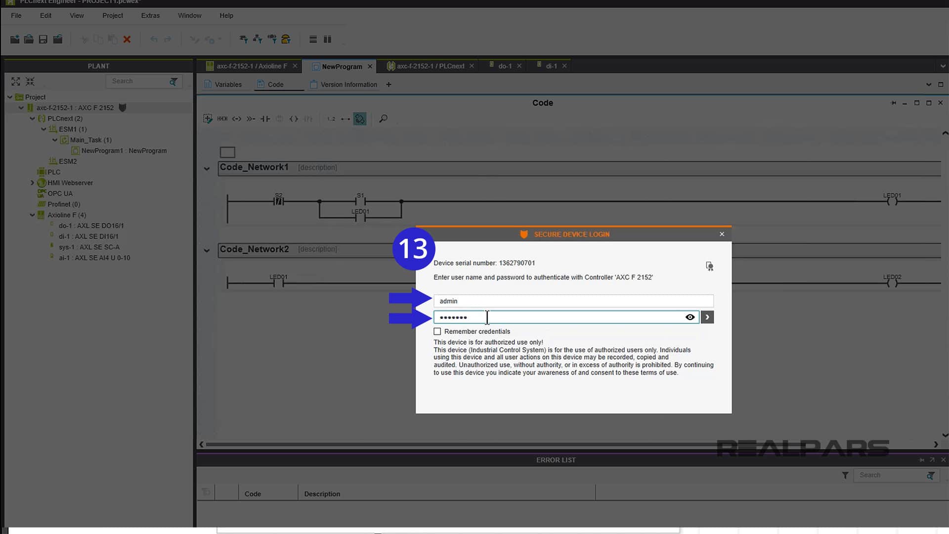
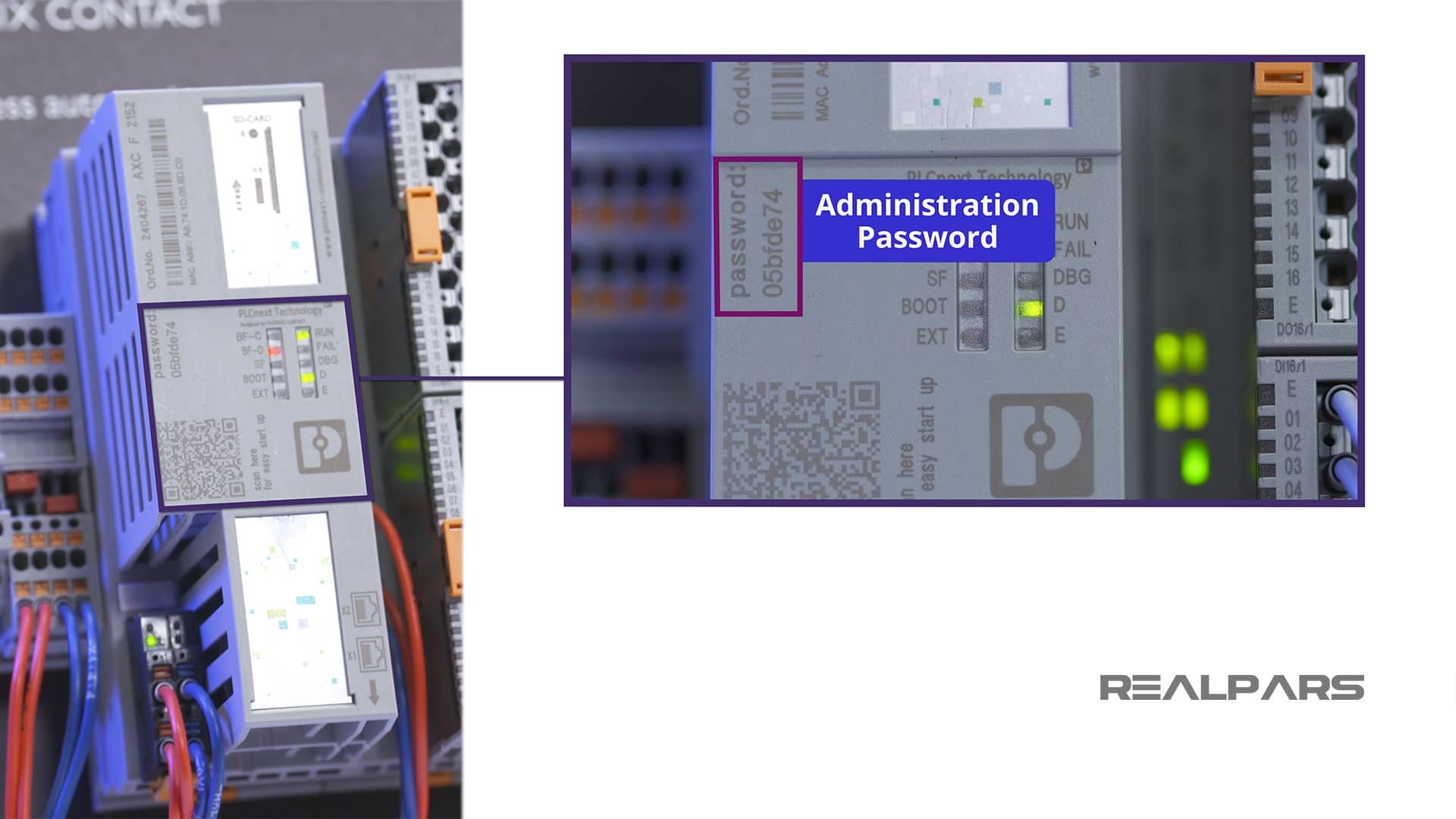
If you do see this screen, enter admin and the password for your Controller. If you don’t remember the password, it is stamped on the Controller itself.
The ladder logic program will download to the PLC and the program will start to run. Go ahead and start pushing buttons on the Starterkit. You should see what the program is supposed to do.
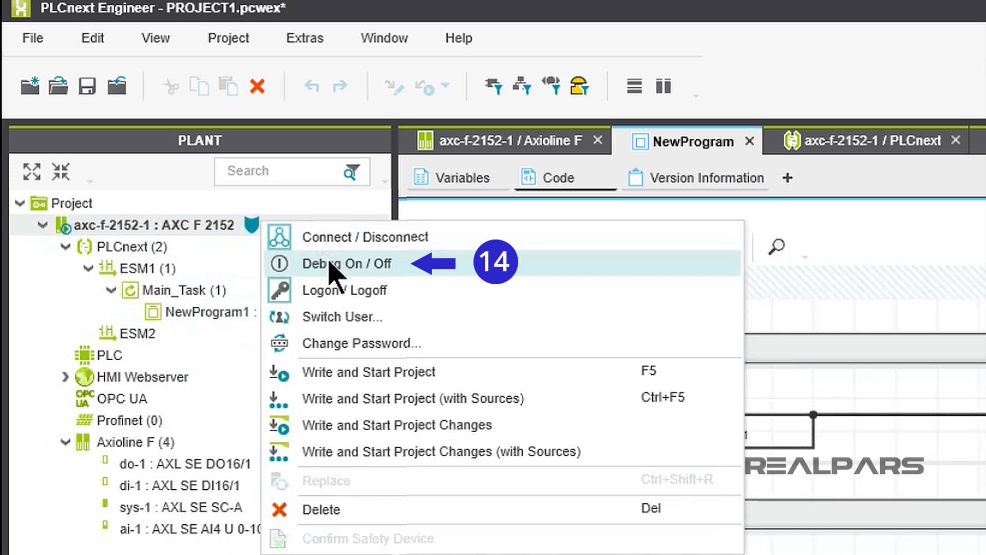
2-3. Debug On/Off
Now for some fun stuff… Right-click on AXC F 2152 under the PLANT column again.
From the dropdown menu, choose Debug On/Off.
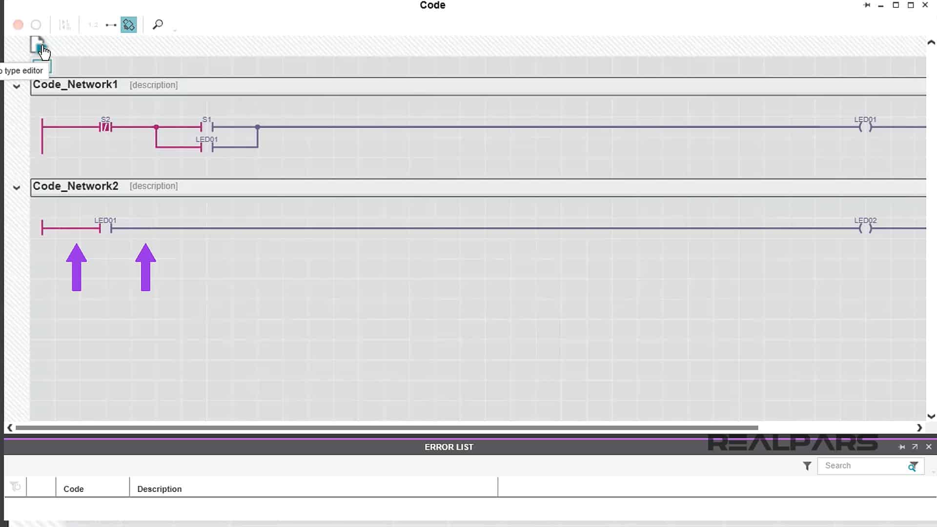
You will notice the workspace changes to grayscale.
Click on the area just above the first network rung, then on the arrow symbol.
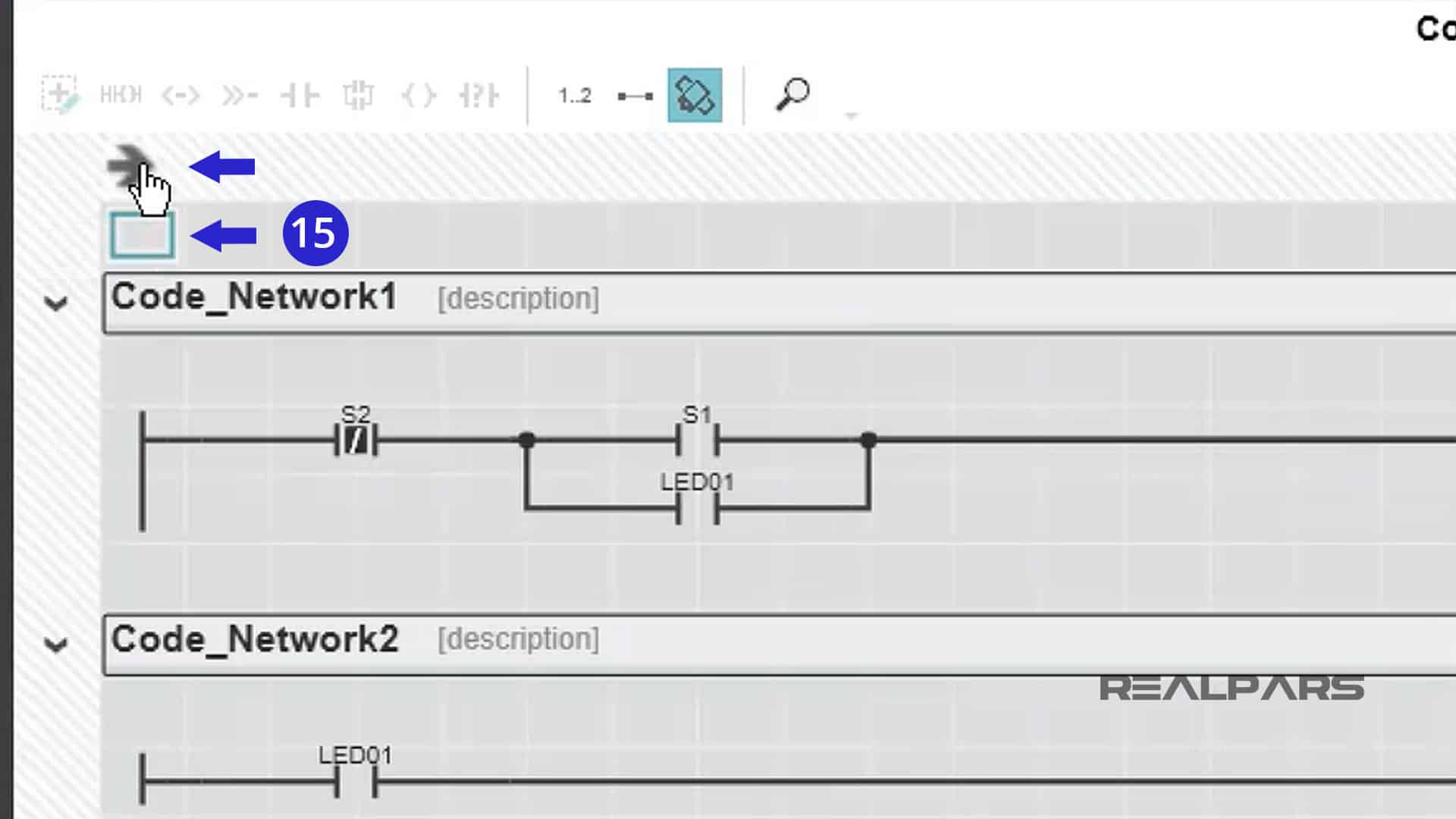
You are now in a mode that will show you real-time worksheet symbol states.
Notice the line and symbol coloring?
Red indicates True.
Grey indicates False.
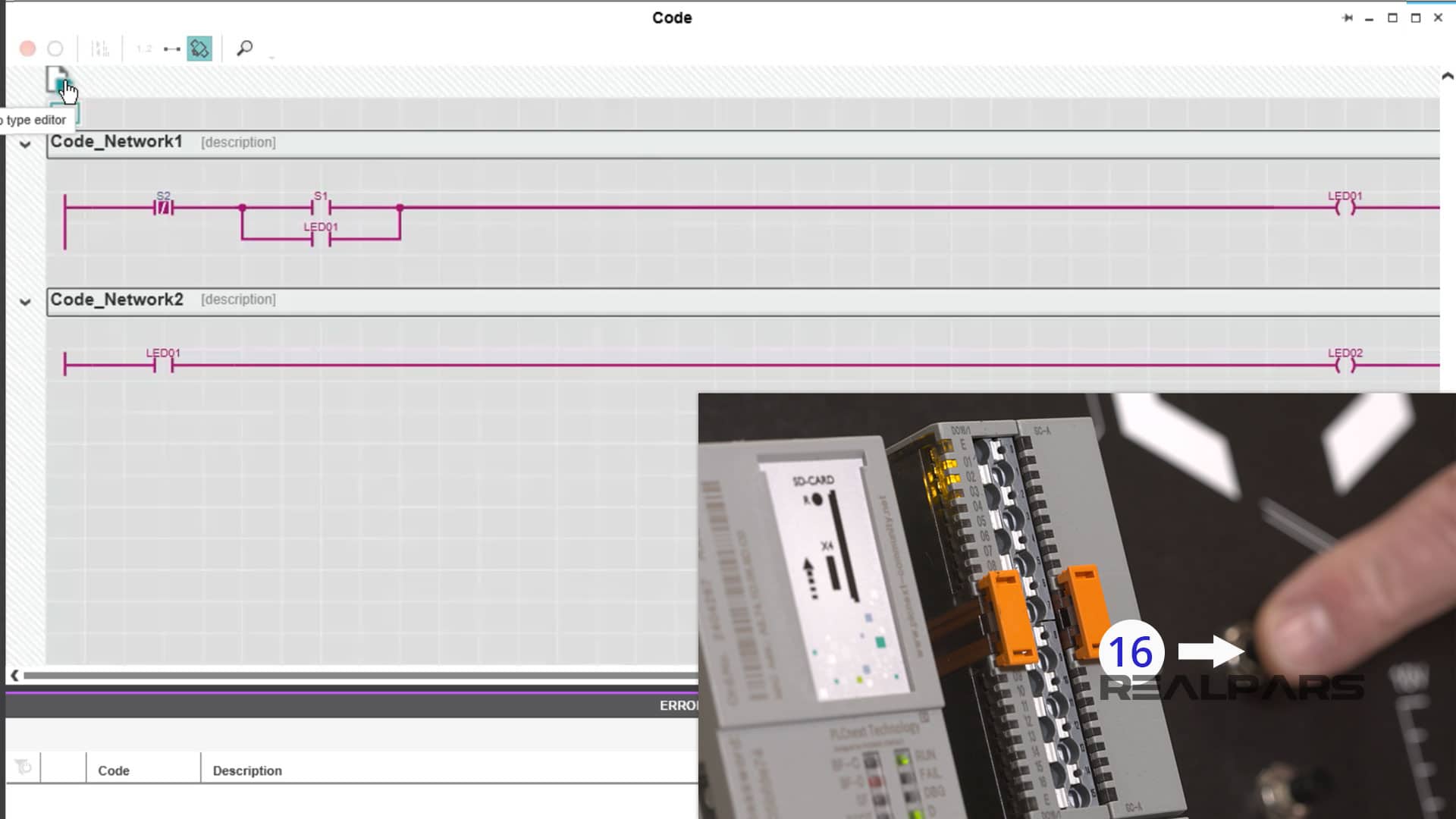
Push S1 and watch its corresponding symbol go true. How do we know it is True? It changes from Grey to Red.
The first rung logic will cause the LED01 symbol to become true and latch across S1.
The second rung logic will cause the LED02 symbol to become true.
LED01 and LED02 on the output module will turn on.
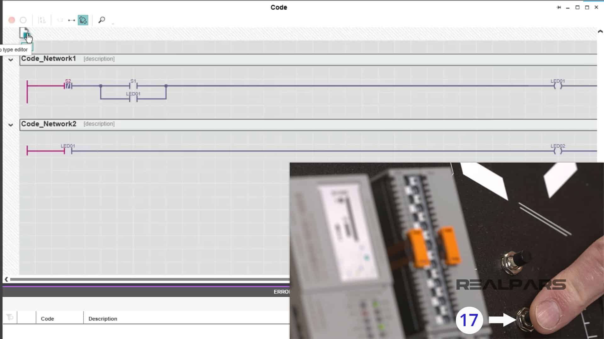
Now push S2 and observe the ladder logic symbol. The S2 symbol will go False which will cause both LED01 and LED02 symbols to go false.
LED01 and LED02 on the output module will turn off.
That should do it for this article!
You have created and written a simple ladder logic program called New Program and downloaded it to the PLC Starterkit for testing!
You’ve just scratched the surface of the capabilities and flexibility of the PLCnext Engineer software and the PLCnext Starterkit.
More fun to come!
PLCnext Starterkit | What’s in the Box? (Part 1 of 4)
How to Create a New PLCnext Engineer Project and Configure Ethernet Port (Part 2 of 4)
▶ How to Easily Create PLCnext Ladder Logic Programs (Part 4 of 4)
Got a friend, client, or colleague who could use some of this information? Please share this article.