
In this article, we’re going to introduce you to the Resistance Temperature Detector commonly referred to as RTD.
We’ll talk about how the RTD works and how it’s used in industry to measure temperature. We’re also going to discuss regular maintenance, calibration, and troubleshooting of RTD circuits.
How does an RTD work?
Let’s begin by discussing how an RTD works.
An RTD is a passive resistive device made from a metal that changes resistance with a temperature change.
If the temperature increases, the RTD resistance increases.
RTDs are made with several different nominal resistance values at a specified temperature. For example, a Pt100 RTD is made from platinum and has a nominal resistance of 100 ohms at 0 ℃.
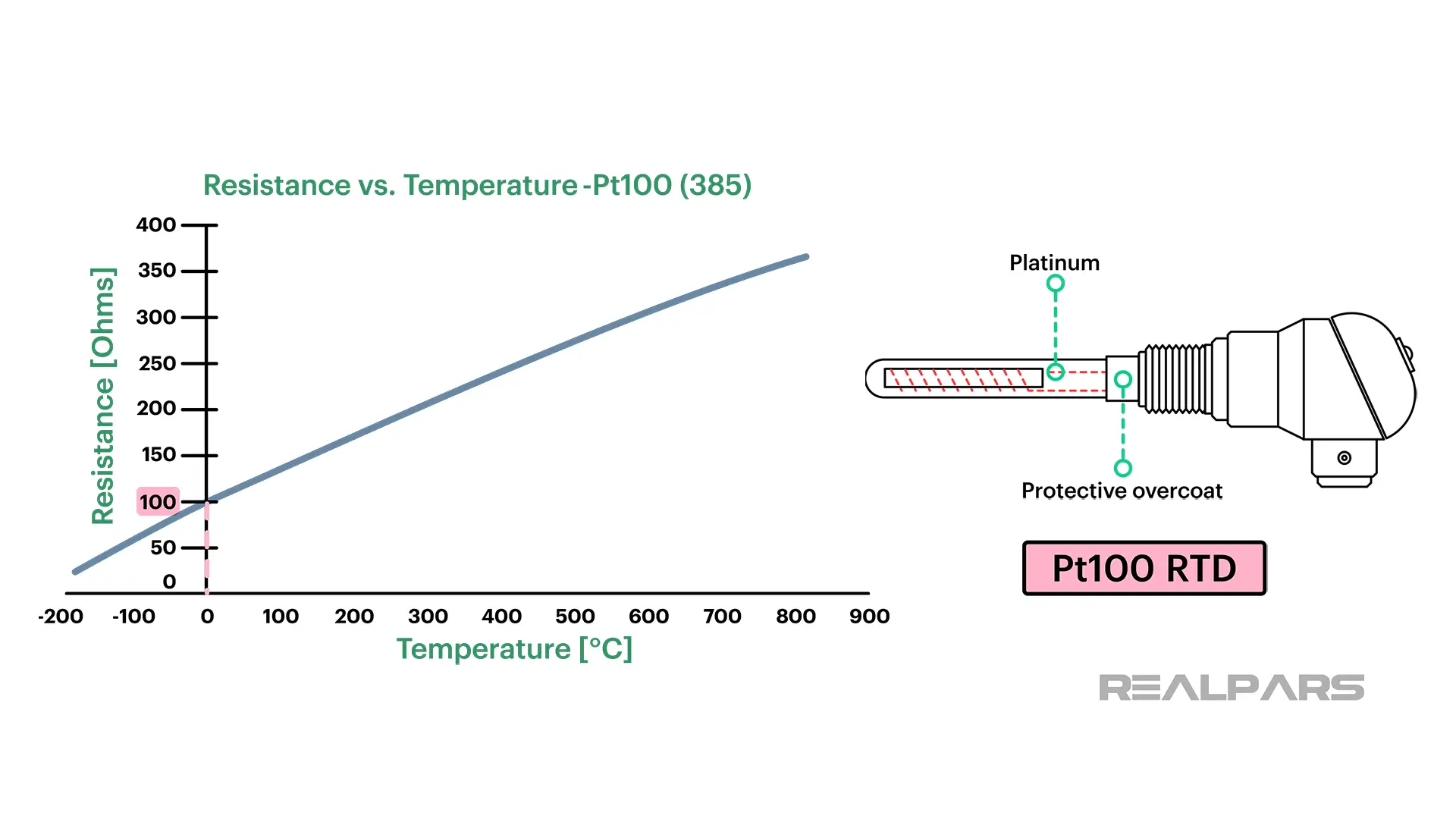
The actual RTD material is housed in a protective overcoat.
So, if we measure the resistance of a Pt100 RTD, we should be able to determine the temperature around it. That’s not how it is done in industry.
How RTDs are used?
In most applications, a current is passed through an RTD to determine temperature.
Using the resulting voltage across it, the RTD resistance can be determined using Ohm’s Law. We’ll discuss how the voltage is created and how it is used to determine temperature later in this article.
Other devices are used to measure temperatures such as the Thermocouple and the Thermistor.
What makes the RTD a good choice for a temperature measurement?
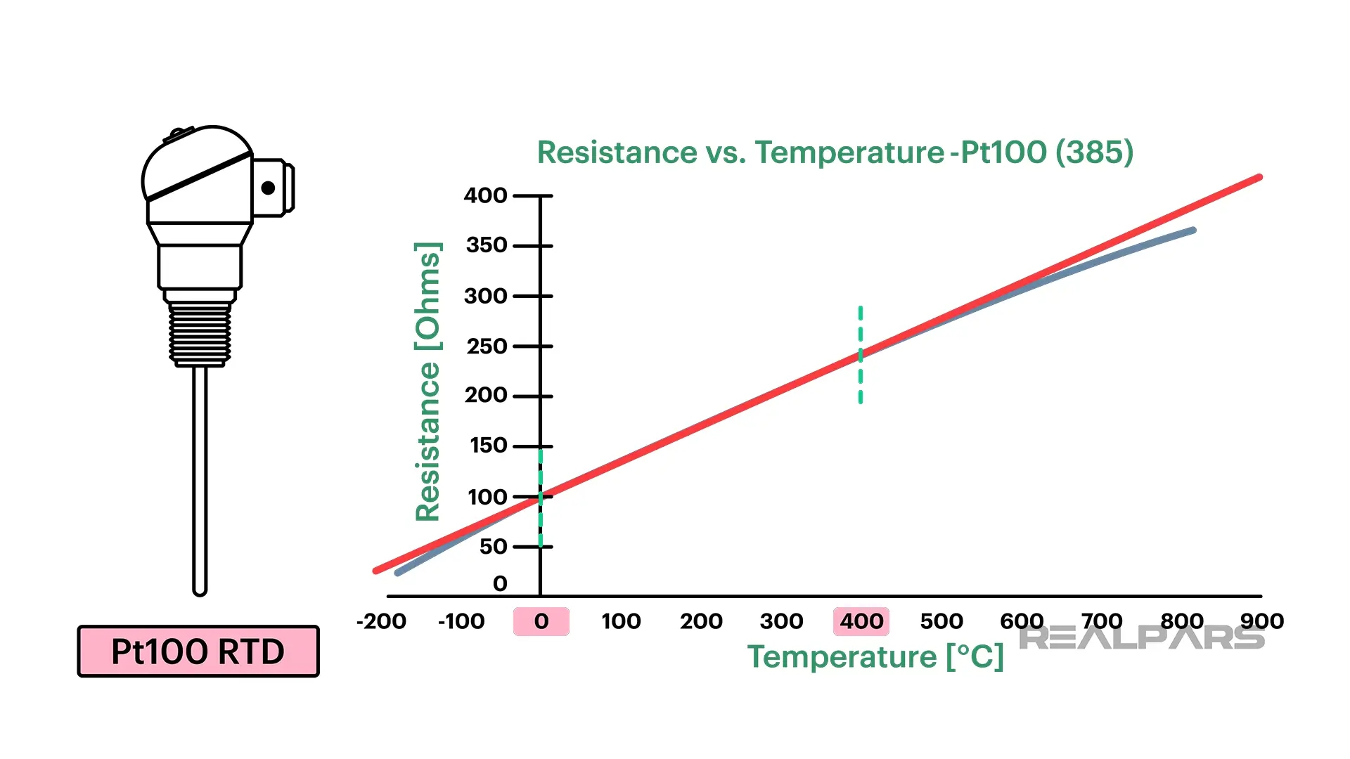
The resistance changes almost linearly with a temperature change. A very good linear range for the Pt100 RTD is 0 ℃ to 400 ℃.
The relationship between temperature and resistance of an RTD is referred to as the temperature coefficient (Alpha). The Alpha of a Pt100 RTD is 0.00385 ohms/ohm/℃.
We can boil this down to obtain what’s called the Resistance Ratio of 0.385 Ω / ℃.
Assuming a temperature of 200 ℃, the resistance of the Pt100 RTD is (200 ℃ × 0.385 Ω / ℃) + 100 Ω = 177 Ω.
That’s what we see from the graph as well.
RTD resistance detection methods
Ok… let’s look at how we detect RTD resistance in industrial applications. Earlier we stated that a current is passed through an RTD and we detect the resulting voltage across it to determine temperature.
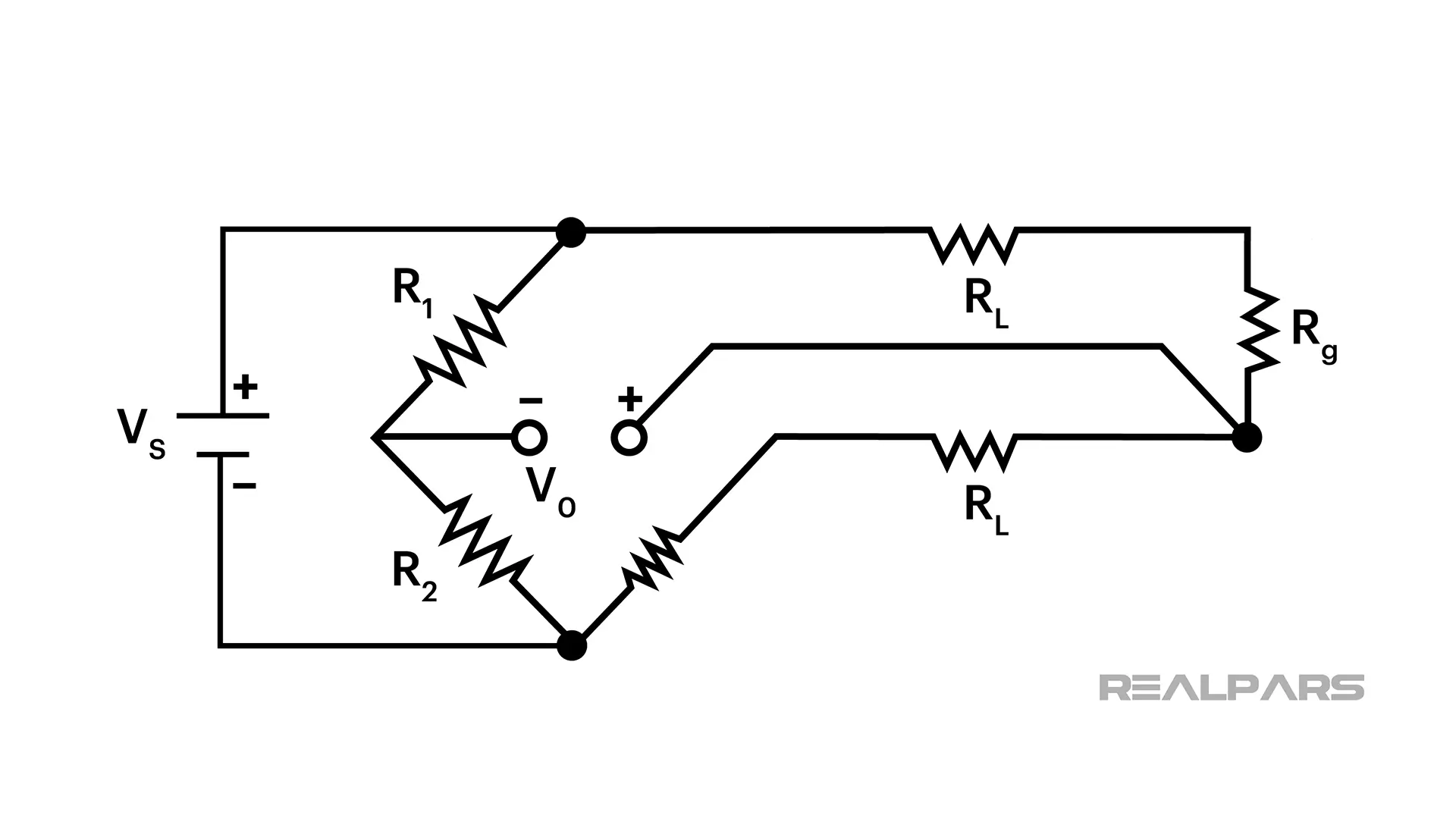
Wheatstone bridge
The Wheatstone Bridge was probably the most commonly used method originally. But, it’s not so common anymore. We will discuss other methods but first, let’s look at the Wheatstone Bridge.
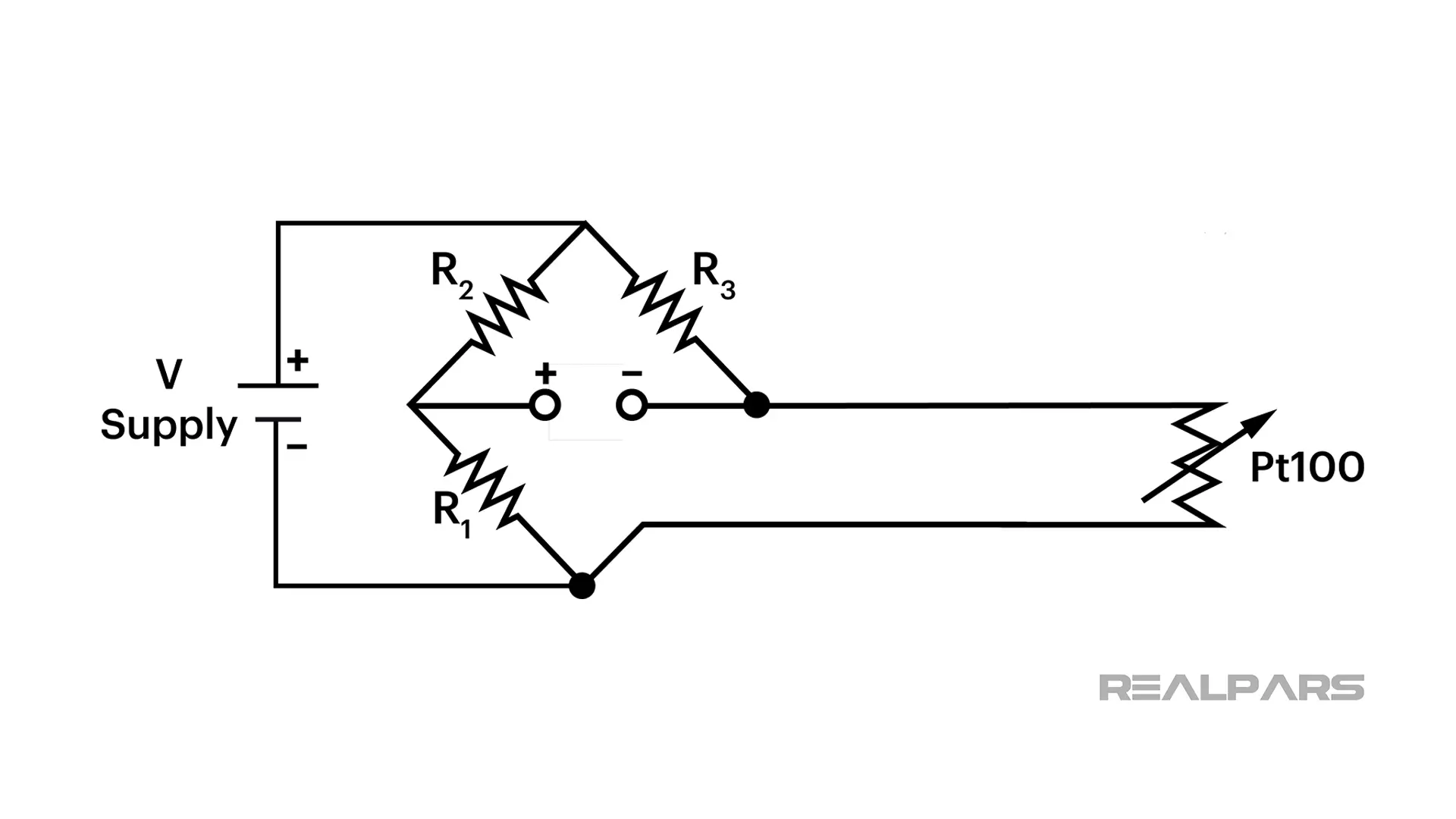
Let’s assume all the resistors in the Wheatstone bridge are exactly 100 ohms. At 0℃, the voltage V will be exactly 0 volts.
If the temperature changes, the Pt100 resistance changes, and the voltage V changes. So, the value of the voltage V represents the temperature at the RTD.
As you can imagine, the distance between the RTD and the bridge becomes an issue because of the introduction of lead wire resistance. Any increase in resistance will produce an incorrect temperature inference.
A drifting V Supply is also problematic as it will affect the voltage V.
Constant current source
So, let’s look at better RTD resistance detection methods.
The Constant Current Source method is very popular. The voltage V is a direct result of the resistance of the Pt100 and the constant current flowing through it.
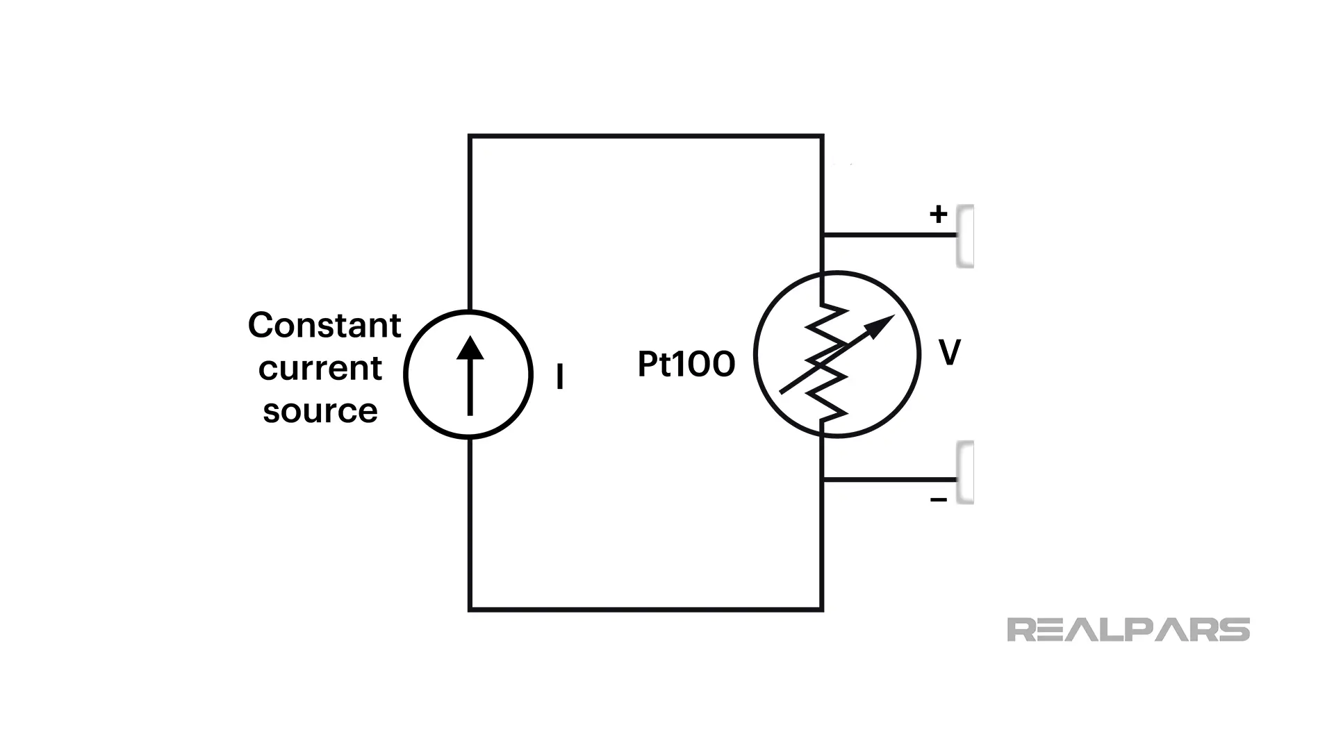
An increase in lead wire resistance does not affect the Voltage V because the current through the RTD is not affected.
2, 3, and 4-wire RTD
So far we’ve only talked about a 2-wire RTD. You will rarely see a 2-wire RTD used in an industrial application because of its inherent problems with resistance detection.
3-wire and 4-wire RTDs are the industry standards as issues with lead wire resistance are eliminated.
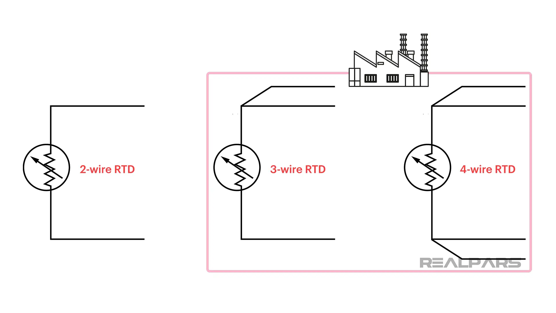
Having a 3-wire RTD connected to a Wheatstone Bridge eliminates the lead wire resistance problem.
Probably the best and most accurate temperature measurement is made using a 4-wire RTD connected to a Constant Current Source transmitter.
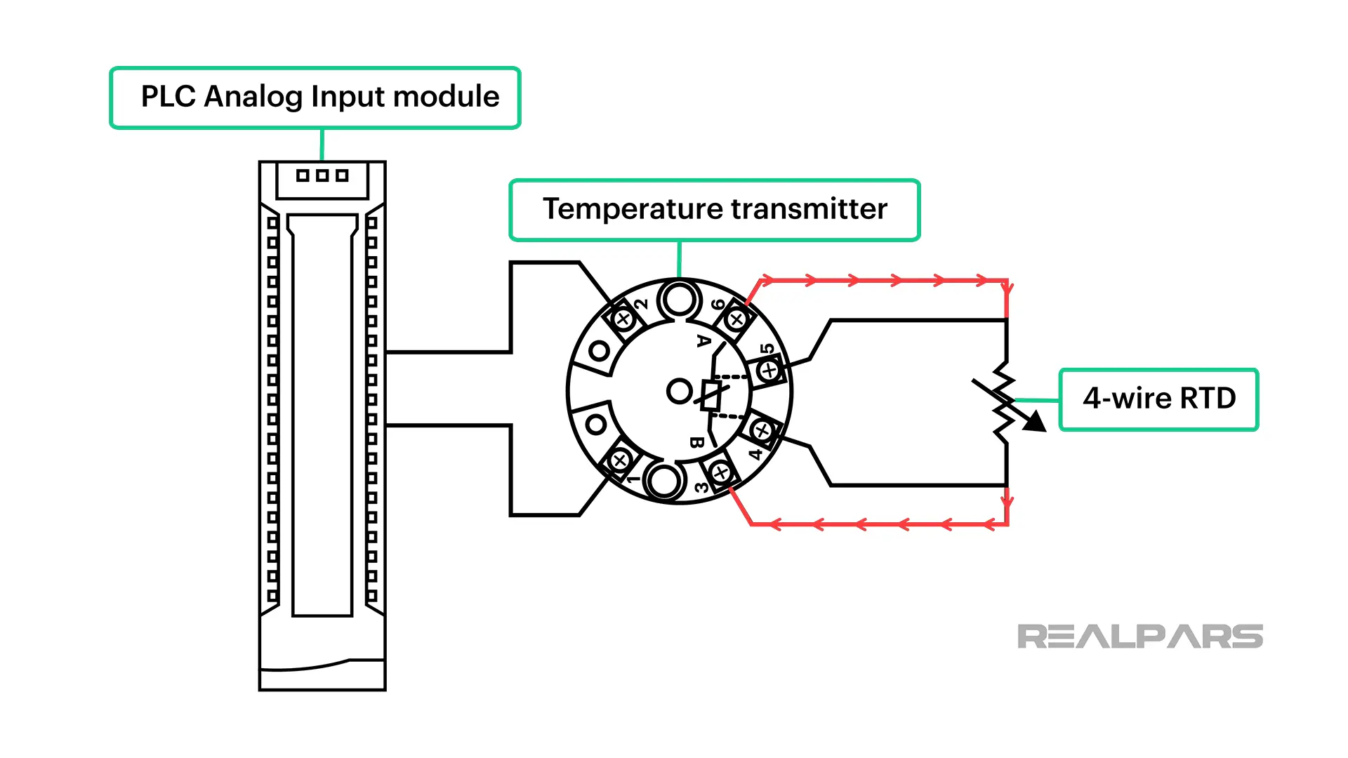
How 4-wire RTDs are used?
The transmitter current is unaffected by the lead wire length. The voltage resulting from the constant current and the RTD temperature is detected by the transmitter.
The transmitter converts this detected voltage and sends a corresponding signal to a receiving instrument such as a PLC.
RTD protection
As you can imagine, it’s not practical to expose an RTD directly to whatever temperature process we’re attempting to measure. And, more than likely, the ambient conditions are not friendly.
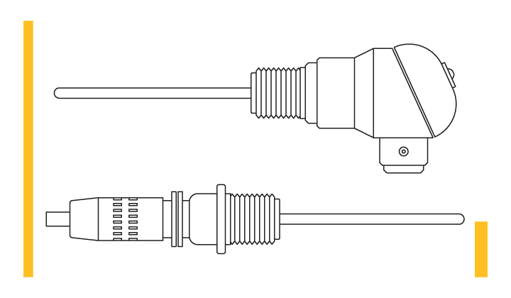
An RTD needs protection. A connection head is used to connect the RTD leads to the transmitter. The connection head also protects from nasty ambient conditions.
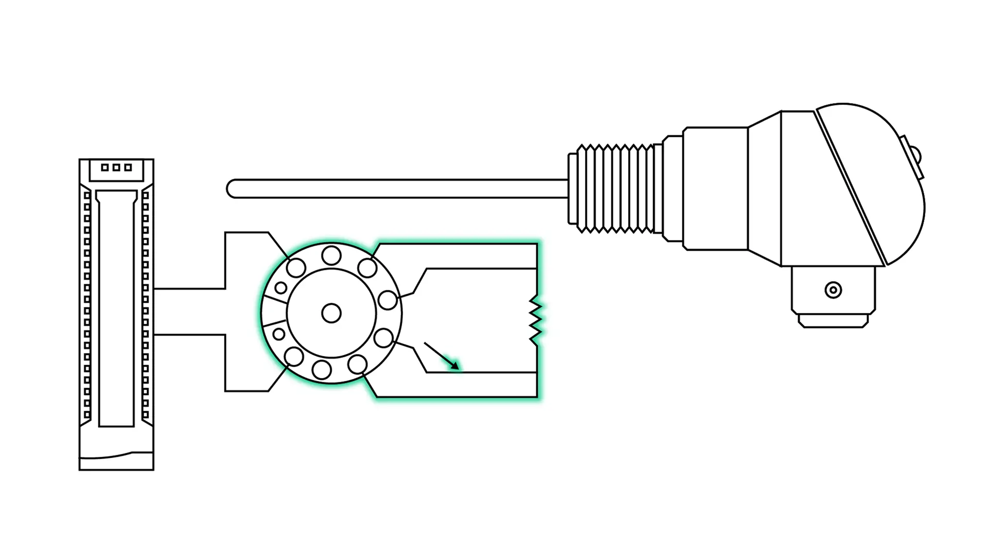
Further protection is provided by inserting the RTD sheath into a thermowell that is permanently housed in a pipe or a vessel. The thermowell protects from potentially damaging process fluids.
The RTD can be easily removed from the thermowell without interrupting the process.
Thermowells create issues such as a delay in detecting process temperature changes.
Thermowell placement is also an important consideration. Questions arise such as where do we place the thermowell in the pipe or vessel, and is the thermowell long enough?
Let’s talk briefly about RTD circuit maintenance and troubleshooting.
RTD maintenance and troubleshooting
Like any instrument or sensor in an industrial environment, problems arise due to corrosion, moisture, and bad connections. Any of those conditions will cause the temperature indications at the receiving device to appear abnormal or erratic.
Of course, a defective RTD will cause issues as well.
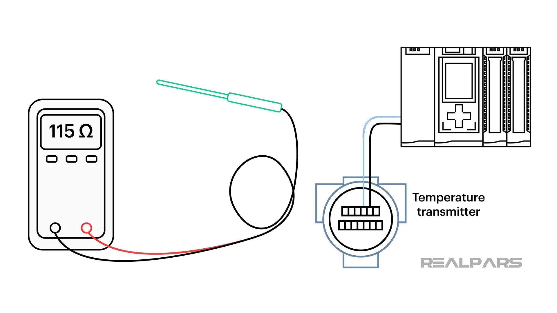
You can perform a very quick and simple test by isolating the RTD and connecting an ohmmeter across it. The RTD will read a finite resistance value of approximately 110 ohms to 115 ohms depending on the ambient temperature.
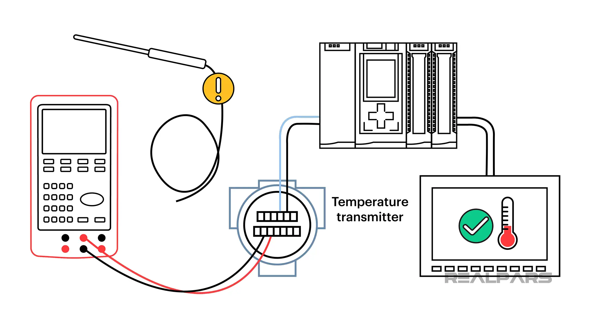
The best way to isolate the problem is by using a process calibrator to replace the RTD in the measurement circuit.
The process calibrator can simulate the RTD by producing a resistance and applying that resistance to the transmitter. In our illustration, if the HMI indicates the expected temperature, the problem is with the RTD.
If you want to know more about process calibrators, check out our article called What is an Instrument Calibrator?
Summary
Ok,… let’s review what we’ve covered in this article…
– An RTD is a passive resistive device made from a metal that changes resistance with a temperature change.
– The RTD resistance changes almost linearly with a temperature change.
– The Wheatstone Bridge was the earliest detection circuit used with RTDs.
– RTDs are available in 2, 3, and 4-wire configurations.
– Constant Current Source transmitter connected to a 4-wire RTD is very common in industry.
– An RTD is inserted into a thermowell that is permanently housed in a pipe or a vessel.
– The best way to check a temperature circuit is by using a process calibrator to replace the RTD.
If you want to become an RTD expert, then our course is perfect for you. Get all the tips and tricks on how to install and troubleshoot these devices like a pro. Don’t miss out on this opportunity to boost your skills and take your career to the next level!