

In this article, we will learn about VFD and its applications. We will also cover in detail the converter and the DC link. Finally, we will cover the IGBT module, and how PWM allows for AC output to the motor for precise motor speed control.
VFD working principle
Rather than just applying the full energizing power to an AC motor, a VFD works by controlling the frequency and voltage of electrical power supplied to it. A VFD allows precise adjustment of the motor's speed and torque for smoother motor starts and stops, ultimately reducing mechanical wear.
AC motor rotational speed
Induction or alternating current electric motors rotate at a rate that is set by the number of poles inside the motor itself, and the power supplied.
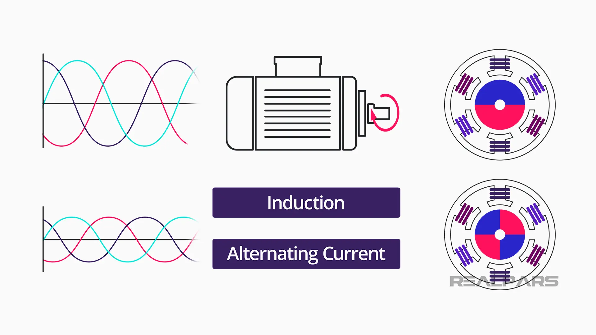
The frequency (measured in Hertz) is directly related to the Revolutions Per Minute (RPM) of a motor. The higher the frequency, the faster the RPM or the higher the engine rotation speed.
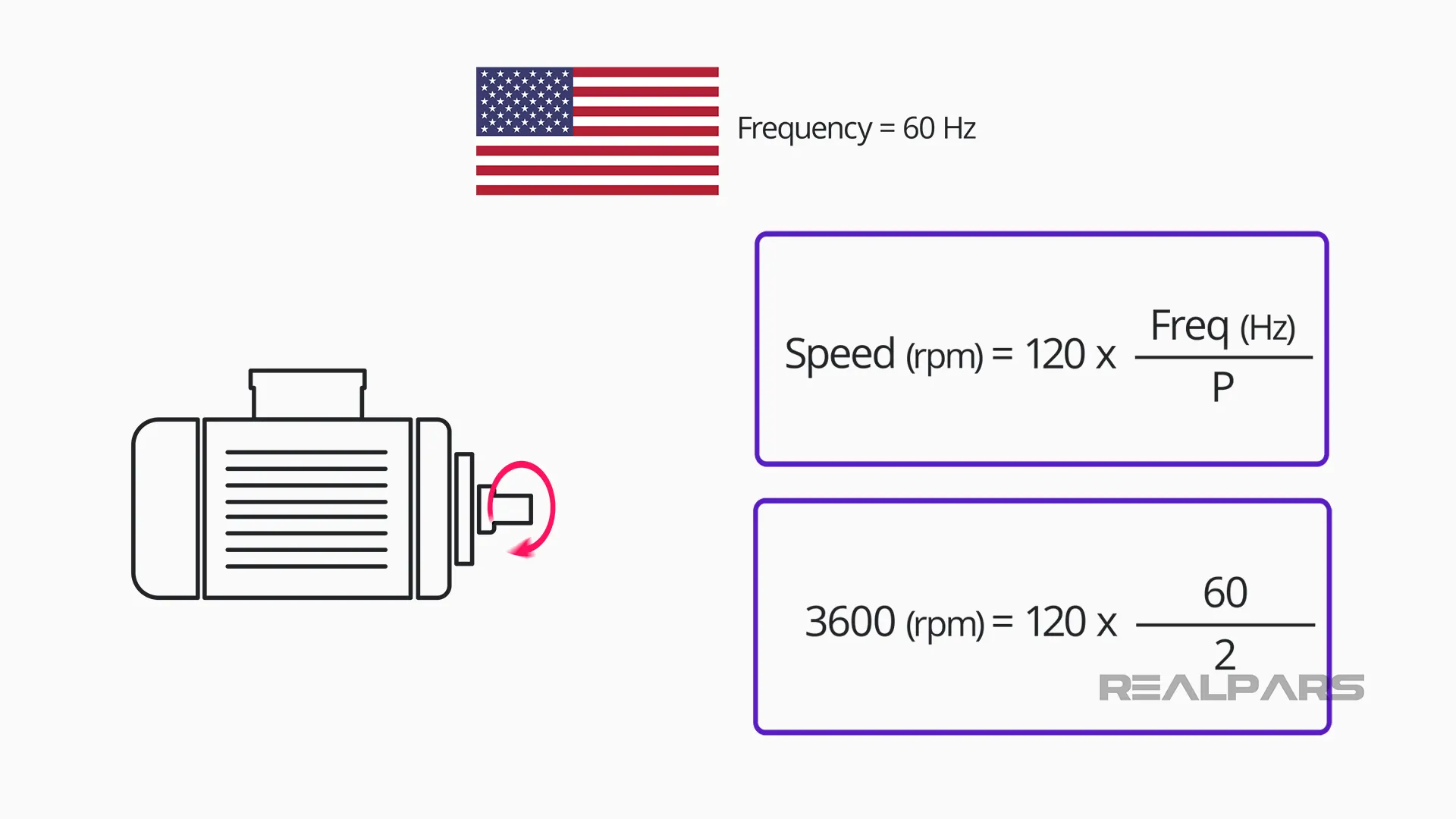
In the United States and in many other parts of the world, electric power utilities provide alternating energy at 60Hz. A standard two-pole AC motor operating at this frequency has a nominal rotation of 3600 RPM.
Speed reduction
If an application does not require an electric motor running at full speed of 3600 RPM, which is very common, a few solutions exist:
1: Using a mechanical speed reducer
It mechanically decreases the output speed by increasing torque – the output gear has more teeth than the input gear.
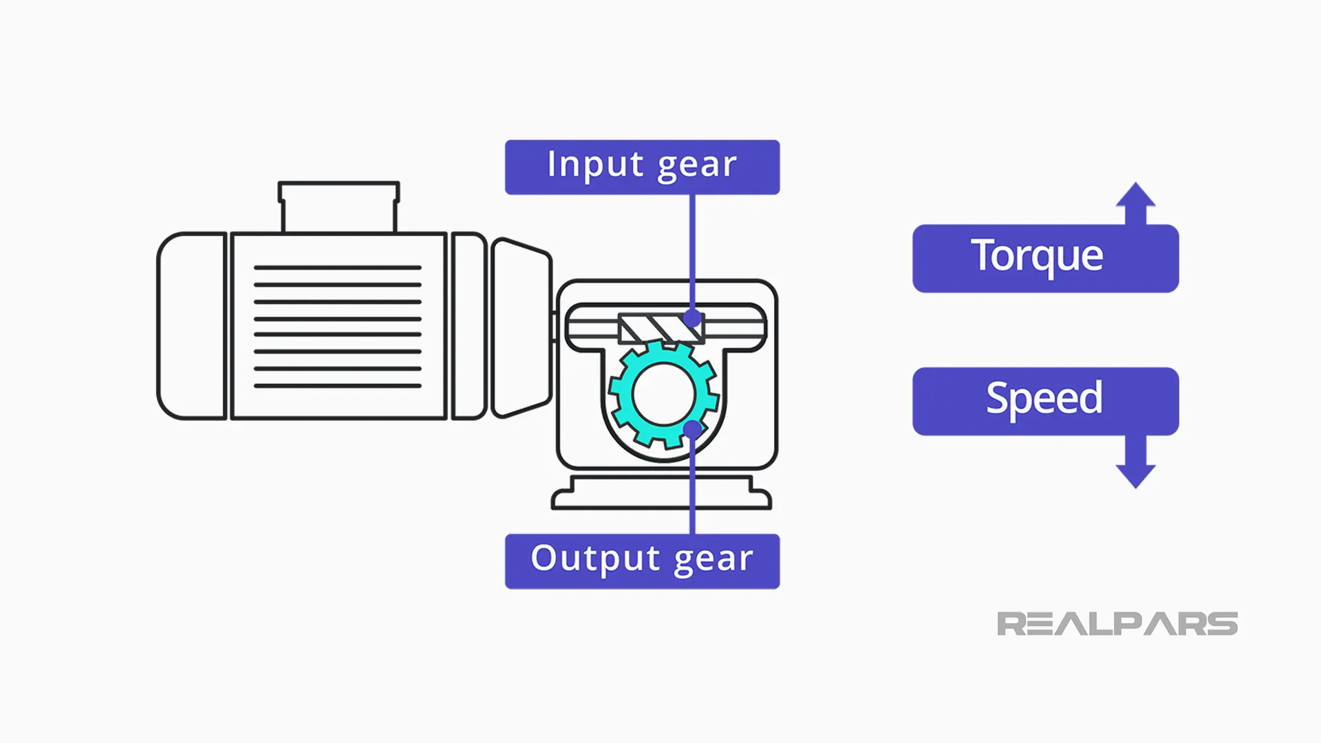
They require lubrication, provide no flexibility, are subtle to vibration and noise, and are not suitable when shafts are distant.
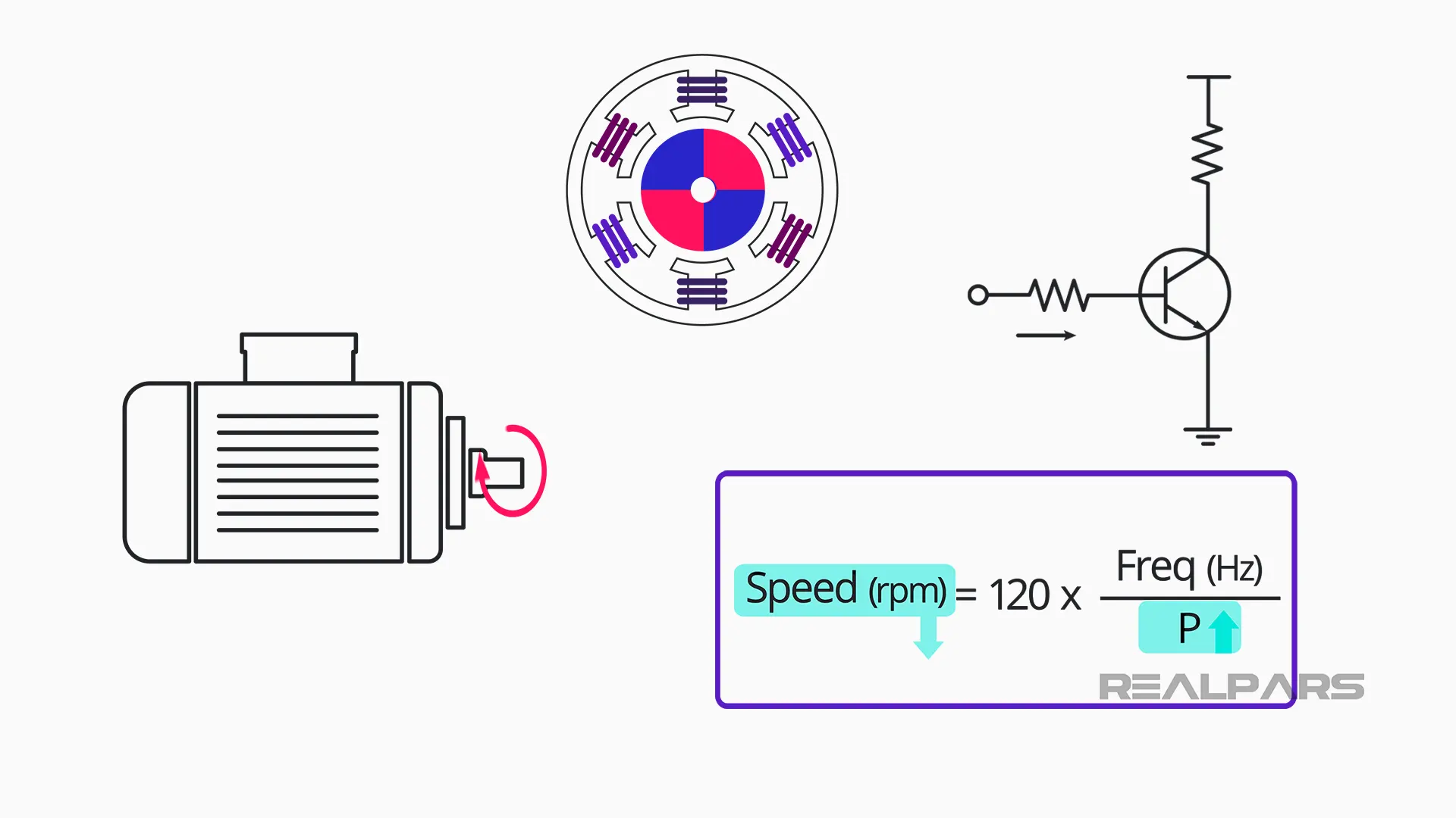
2: Adding more sets of poles
It reduces the speed without altering it electrically. Currently, there are transistor systems that allow for poles inside motors to be turned on and off. However, those systems can be complex and don’t provide fine control.
3: Using a Variable Frequency Drive (VFD)
The advantage of VFD motor control is that it can be configured and fine-tuned to generate a ramp, frequency, and voltage so that the motor operates according to the load requirements (desired speed and voltage).
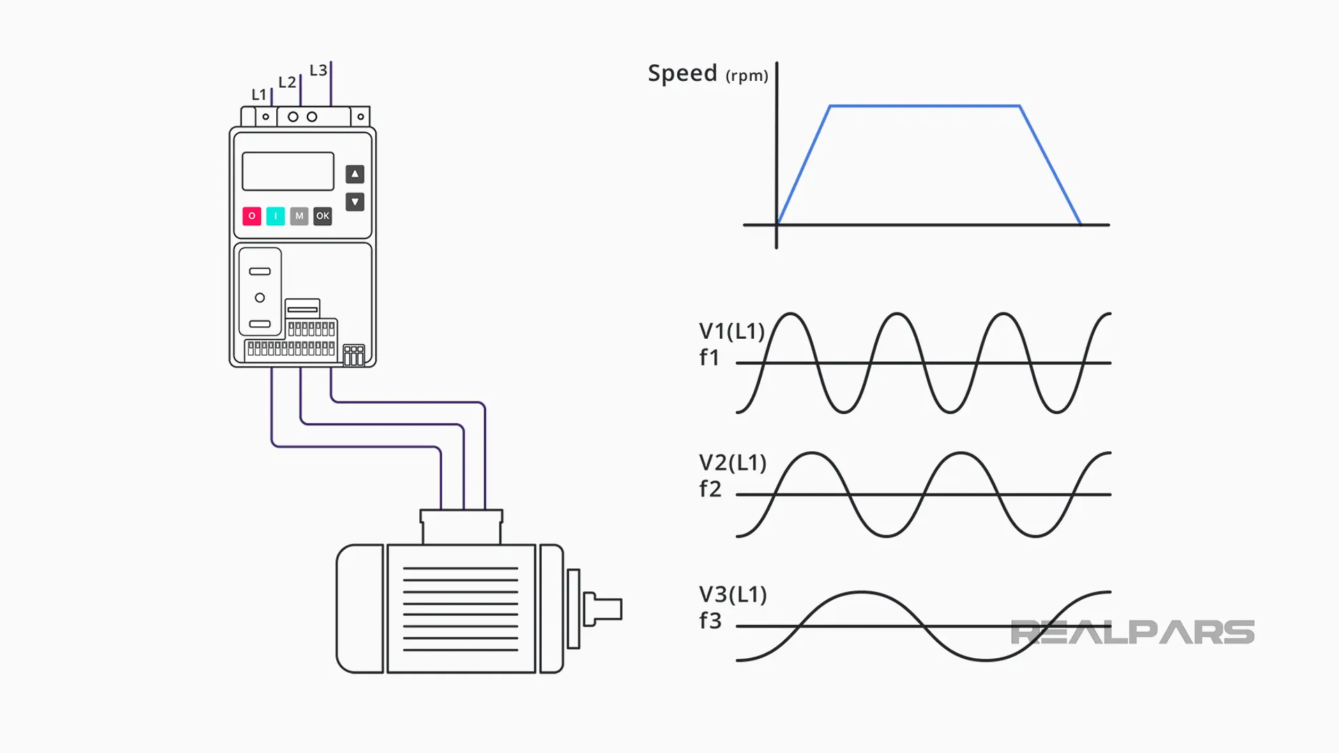
An important feature of the variable frequency drive is that as the motor speed requirements in a given application change, the drive can simply raise or lower the motor’s speed in order to meet new operating requirements, which would not otherwise be possible by using only the mechanical speed reducer, or the transistor system to add more poles.
VFD applications
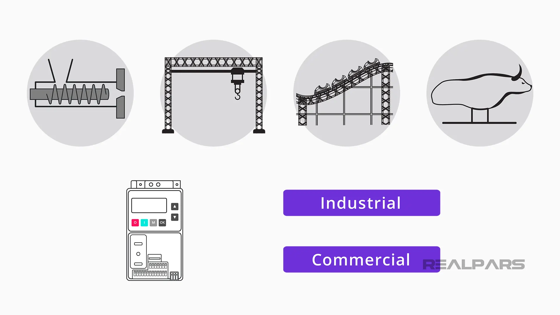
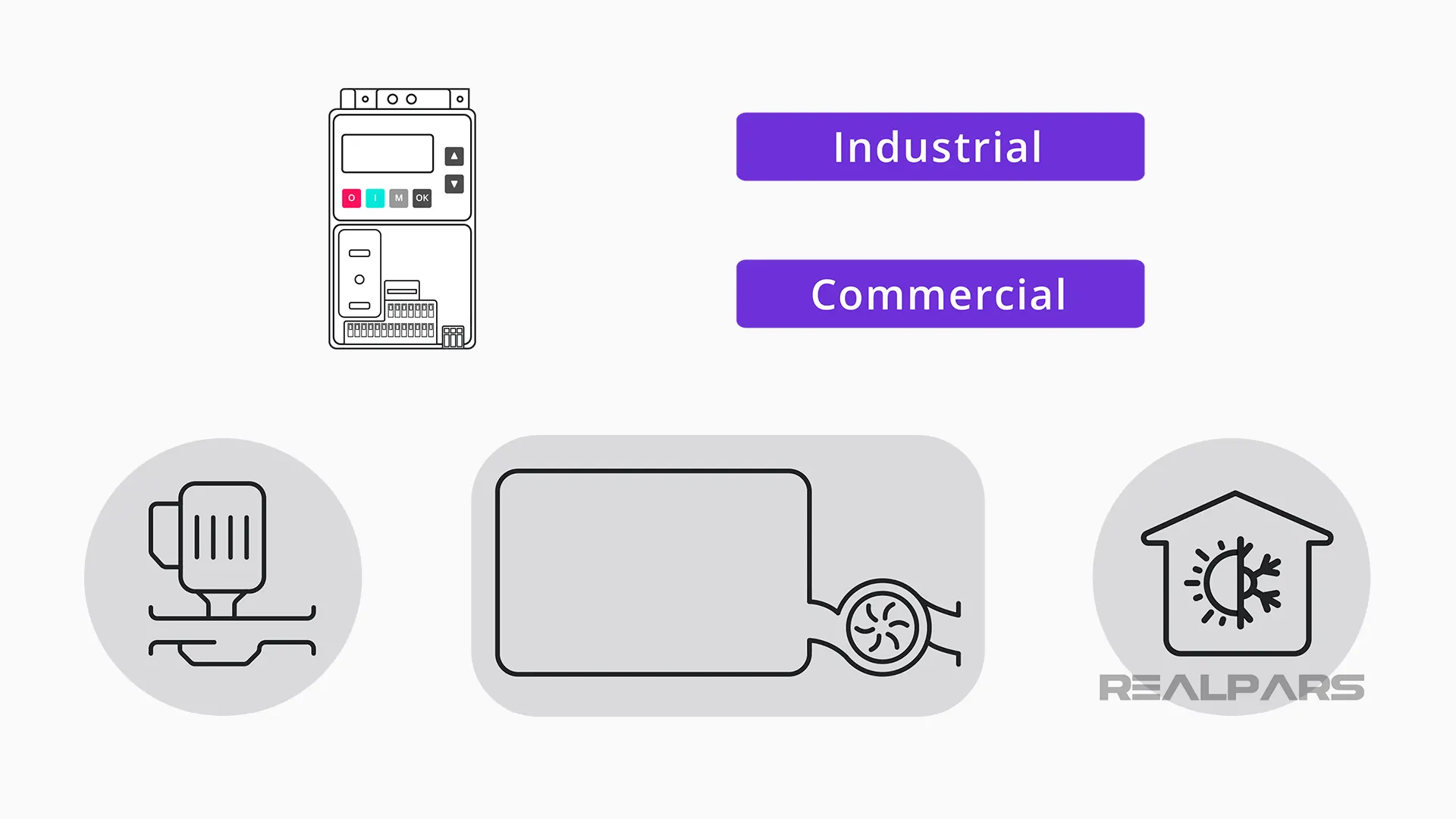
The use of variable frequency motor controllers is widespread in numerous industrial and commercial applications.
- In industrial applications, VFDs are used to control from extruders, and electric cranes, to roller coasters, and mechanical bulls, with so much in between!
- In commercial applications, VFDs are widely used in pumps to control flow and even volume in a tank, as well as in the HVAC industry, being considered green technology.
Ultimately, a VFD varies the supplied frequency to an AC motor in order to control its speed; allowing a smooth startup, and adjusting motor speed as the application requires.
Now that we know why and where variable frequency drives are used, let’s dive into the How does a variable frequency drive work?
VFD electrical circuit
Let’s look at this VFD diagram:
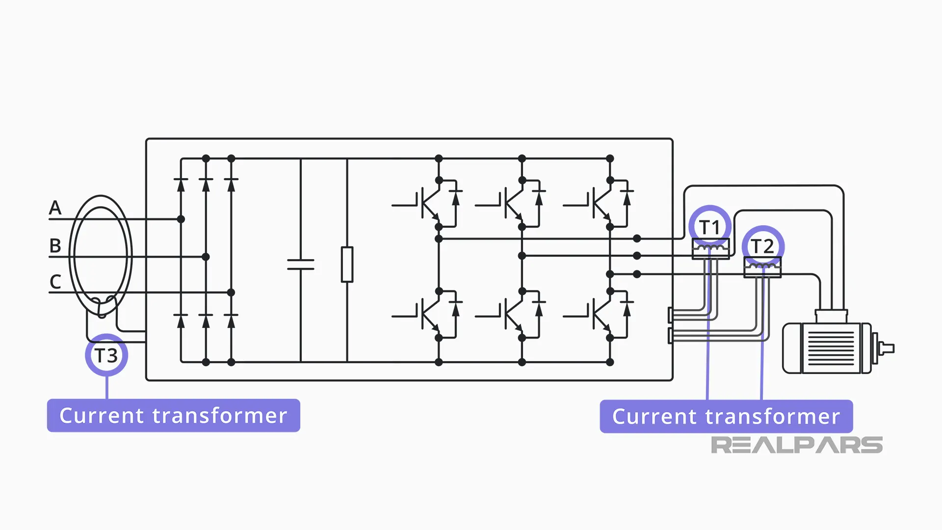
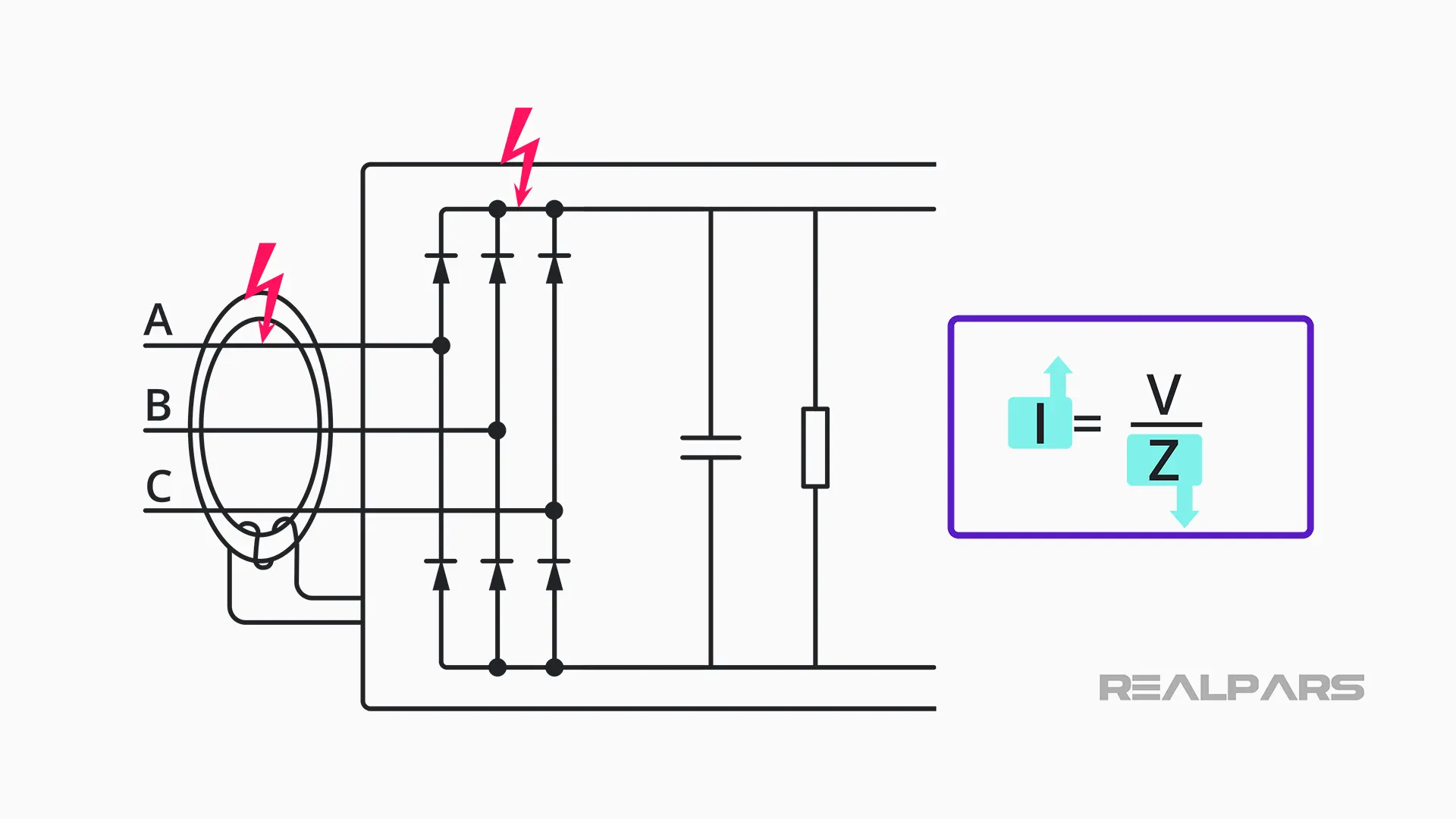
The first thing we find (T3) is a current transformer, which has the function of measuring the current entering our VFD so that the VFD controls can compare the current entering and the current leaving the VFD – measured by the two current transformers indicated by T1 and T2.
If the current measured is different, the VFD will disarm due to what we call a ground fault.
Six-pulse rectifier or converter
Following, we have the converter, also called a rectifier. If we were to expand and look at the rectifier diagram, this is what it would look like:
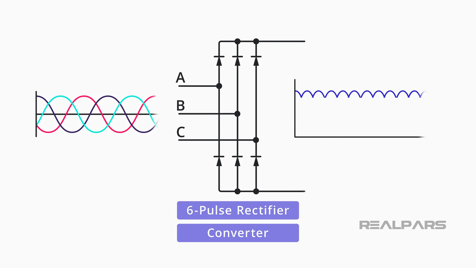
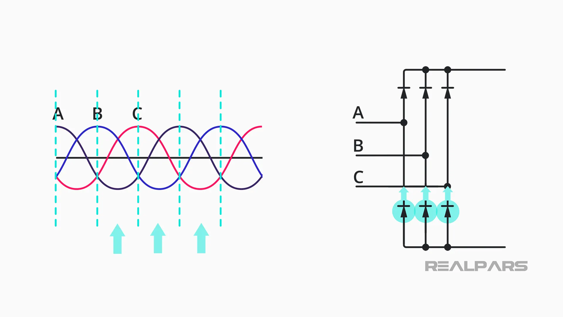
This is called a six-pulse rectifier or converter, and it’s where the three-phase alternating current gets converted into direct current by the use of diodes.
Using an analogy of a hydraulic system, those (six) diodes can be equated to check valves. The form in which the diodes are connected with each other is very strategic.
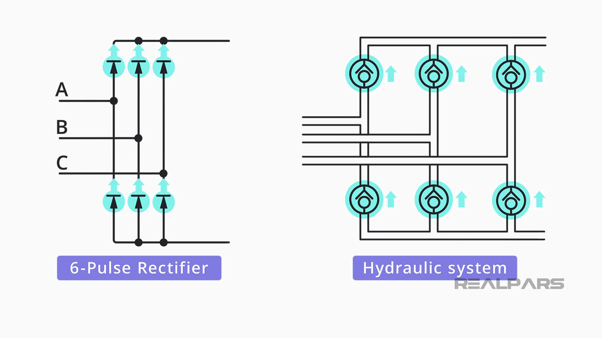
Check valves only allow flow in one direction, such as our diodes with the current flow (the direction is shown by the arrow on the diode symbol).
The electric current passes through the diode in the direction of the arrow on the diode drawing, that is, the current goes from the anode to the cathode, as shown in this image:
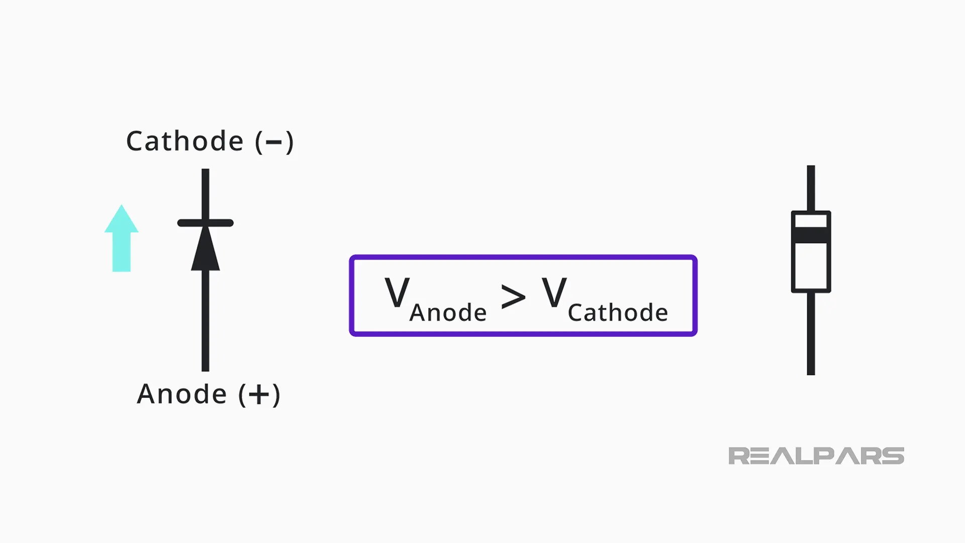
There will only be electrical current if the voltage at the anode is greater than at the cathode.
Therefore, when we connect a three-phase alternating current to the converter:
- When phase A is greater than phase B or C voltages, this diode opens, allowing current to flow,
- When phase B becomes greater than phase A, then it is phase B diode that opens while phase A diode is closed,
- The same is true for C, as well as for the three diodes on the negative side of the bus.
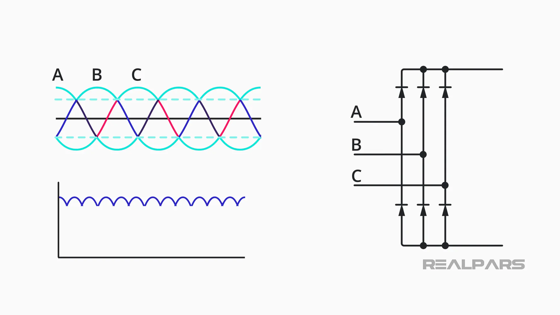
That results in six pulses of currents as each diode opens and closes. The resultant waveform will look like this:
DC bus or DC filter and buffer
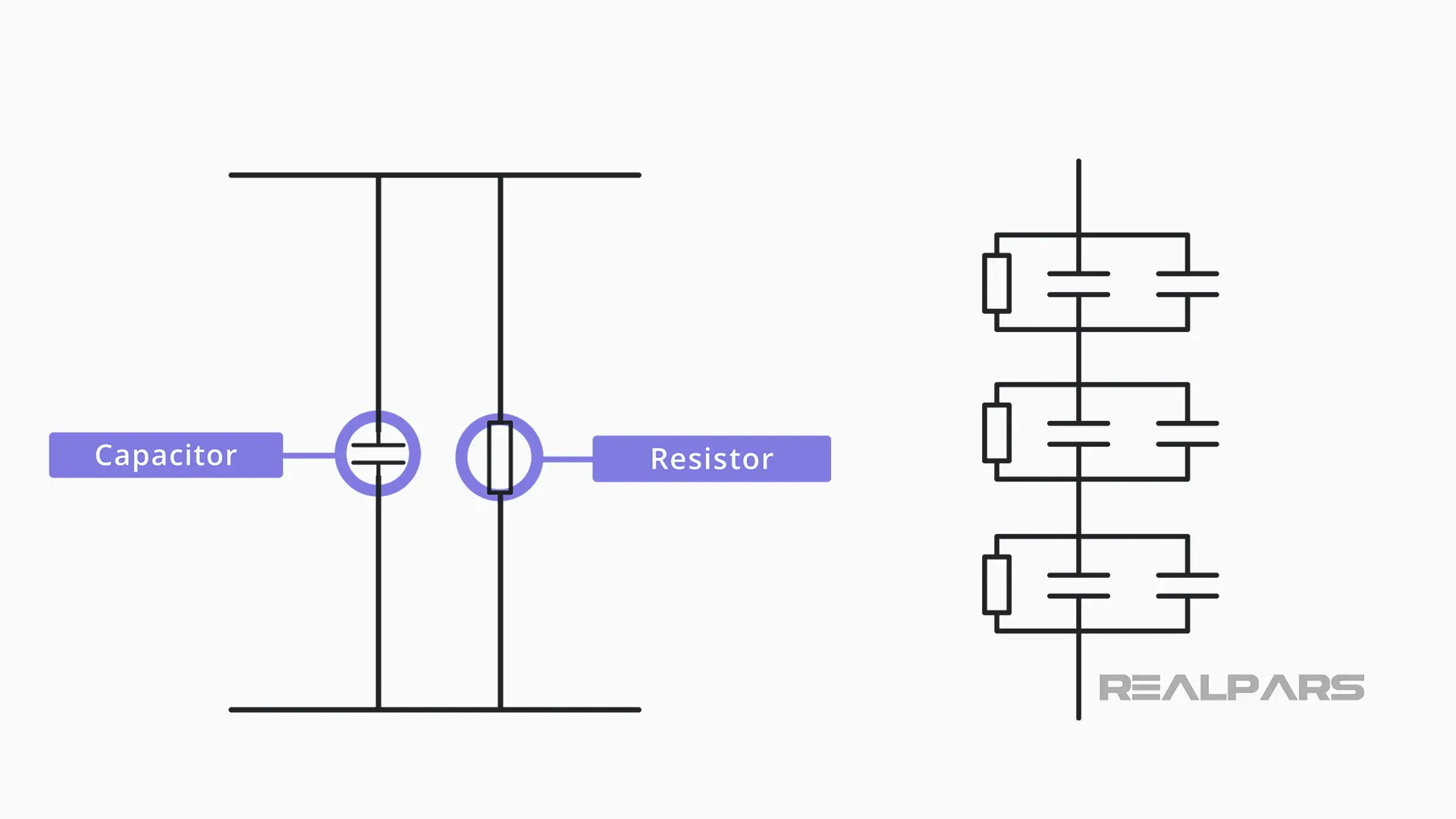
Next, we have the DC filter and buffer, also known as the DC bus. The DC bus is represented by only one capacitor and resistor on the diagram, but in reality, there are various capacitors and resistors associated in series and in parallel.
Since the capacitors are not charged, their impedance is very low. If we were to charge them, the initial inrush could damage the input power devices, or the rectifier/converter, in case the entry fuses didn’t interrupt the circuit.
So instead, we have a pre-charge circuit. Pre-charge is a current limiting circuit that slows the charge rate of the bus capacitors during power-up.
The pre-charge circuit shown here is composed of:
- a contact,
- a resistor,
- a thermostat.
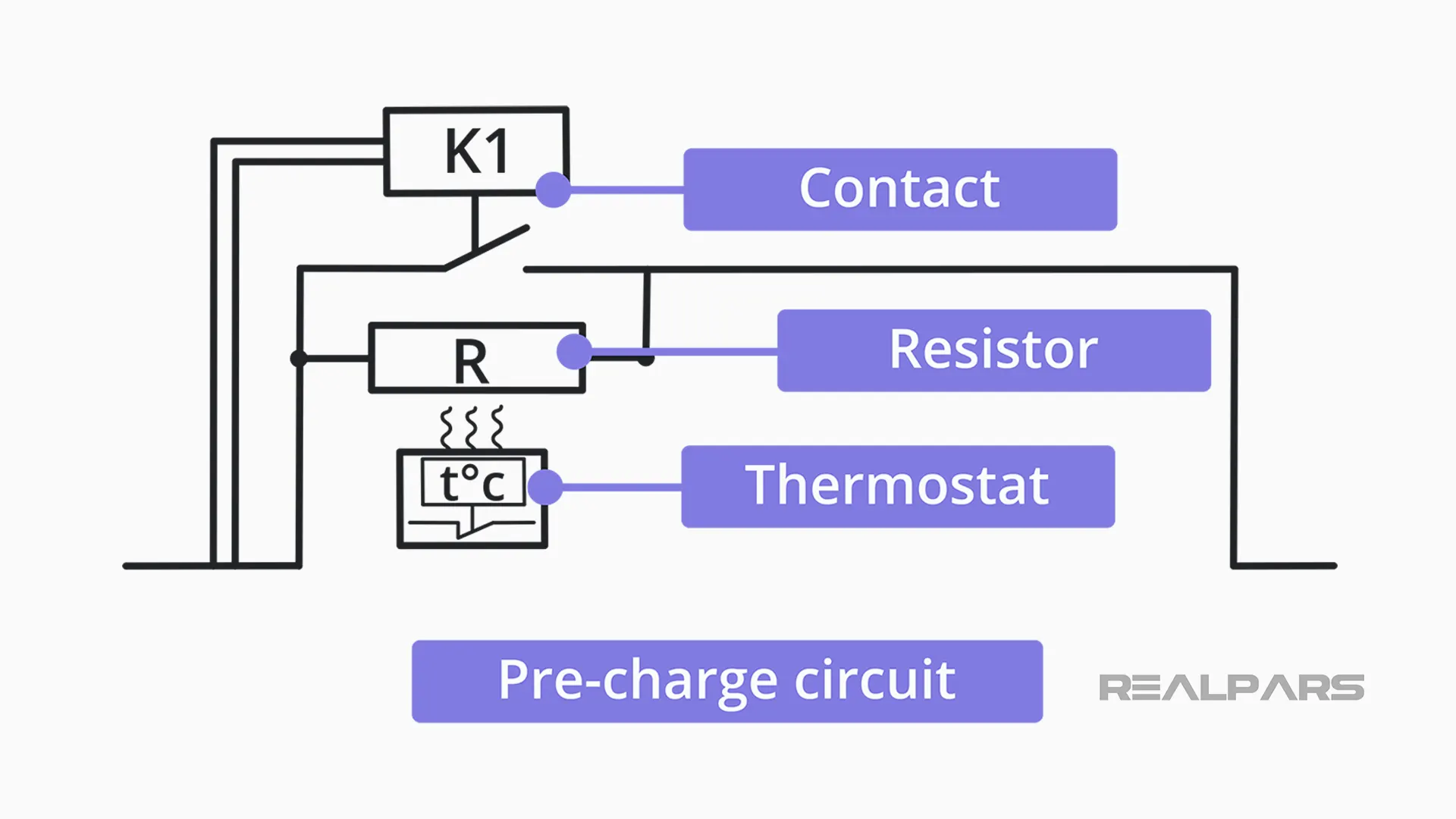
When we energize our VFD, and the bank of capacitors is not yet charged, the capacitors start to charge by the resistors – once the VFD controls identify that the DC link is fully charged, it will then close the contact becoming the path of least resistance for the electric current.
In the scenario of the contactor not closing, and the VFD still starting the motor, the current flowing through the resistor will increase, which will overheat the pre-charging resistor. The thermostat will then act, and it will disarm the VFD due to overheating.
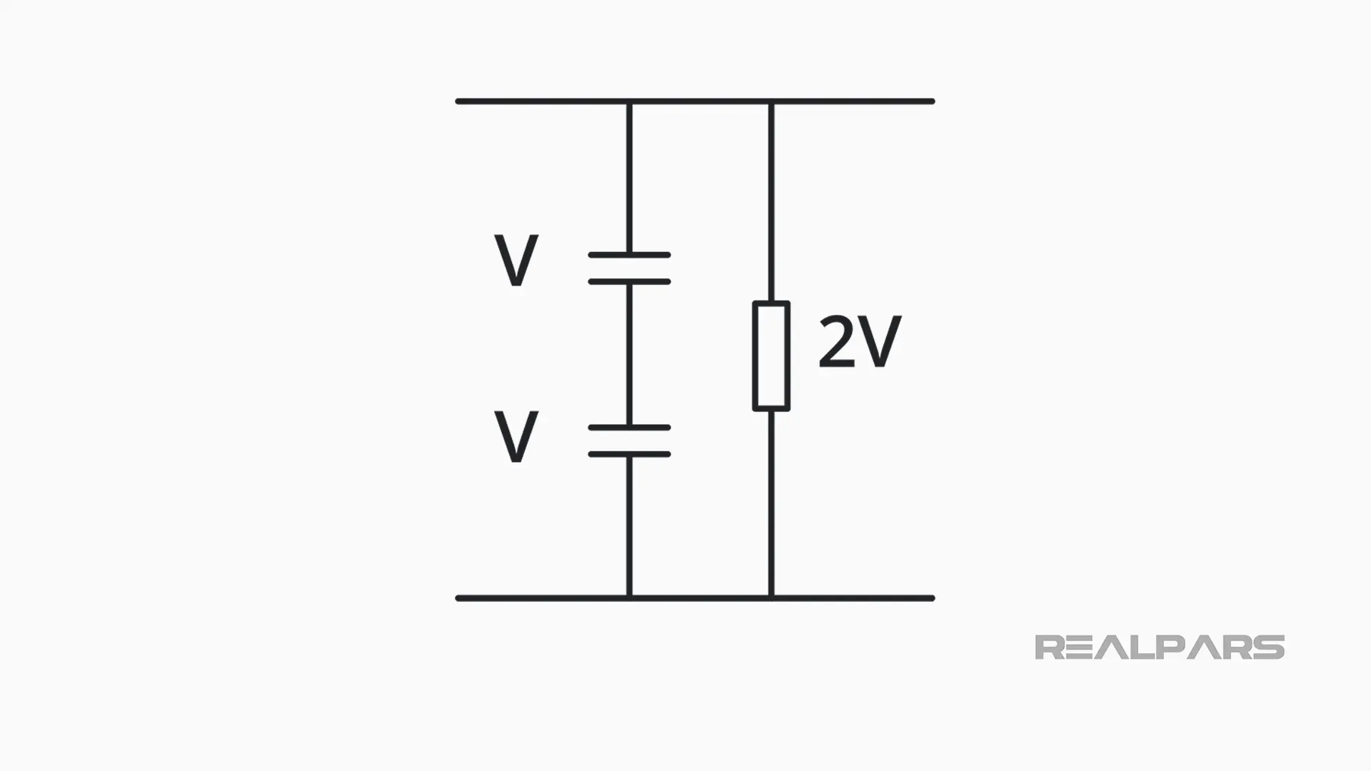
Now let’s go back to the DC bus – its resistor function is to divide voltage and it will guarantee that all capacitors have the same voltage.
IGBT
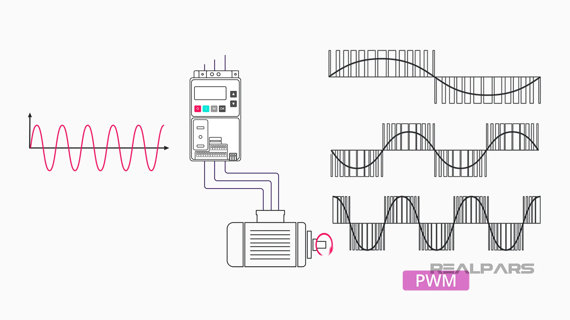
Finally, we have the IGBTs, which is the last step of the drive output: the DC to AC converter and our PWM output.
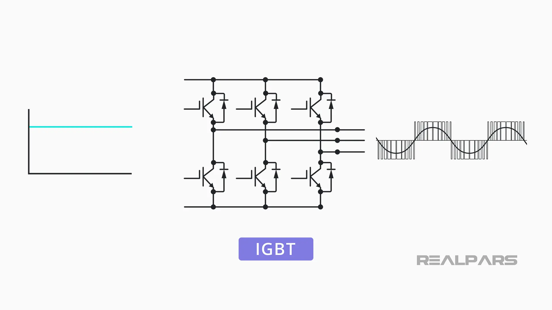
We know that this last step will then convert the direct current into the alternating current as a Pulse Width Modulated output. But… What does that mean? And how does that happen?
It is impossible to talk about VFDs and Insulated Gate Bipolar Transistors, also known as IGBTs without understanding what Pulse Width Modulation (PWM) is.
An analog input signal can be modulated by generating variable width pulses to represent its amplitude. In a very brief summary, PWM is a way to control analog signals with a digital output.
To understand the IGBT’s function in a VFD, it is important to understand how an IGBT works singularly.
How does an IGBT work?
At the simplest level, an insulated gate bipolar transistor (IGBT) is a switch used to allow power to flow when it is turned on and to stop when it is turned off.
It is important to note, however, that they have the capability of switching on and off several thousand times every second!
An IGBT is a solid-state device, which means it has no moving parts.
Rather than opening and closing a physical connection, it is operated by applying a voltage to a semiconductor component, called a gate, that changes its properties to create or block an electrical path.
Let’s look closely at a typical IGBT: The terminals (pins) represent the Gate, the Collector, and the Emitter.
Current flows along the conductance path composed by the Collector and the Emitter, while the Gate controls the device.
Here is an electrical drawing representation of it.
The IGBT behaves similarly to a switch. As the word itself suggests,
- when a positive voltage is applied, the Gate will close (turn on), allowing current to flow between the collector and the emitter;
- if not enough voltage is applied, the Gate remains closed (turned off) not allowing for any current to flow between the collector and the emitter.
To prevent the device from closing, this voltage is kept negative in this off state.
PWM signal
Now that we have an understanding of how our IGBTs work, let’s go back to the application of IGBTs in VFDs, and let’s represent our IGBTs as contact switches for a simpler understanding.
The top IGBTs, which in our representation are switches are in the positive DC bus, and the lowers are in the negative DC bus, so when one of the top switches is closed, that motor phase and voltage then become positive.
On the other hand, when one of the lower switches is closed, that motor phase and voltage then become negative.
Therefore, by controlling the speed and sequence that those switches open and close, we can control the phases and frequency of our signal: zero, negative, or positive.
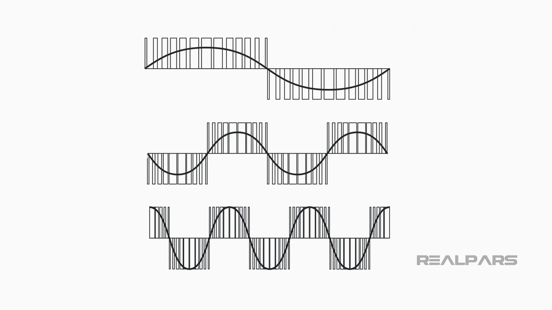
It is important to note that VFDs output signal is a PWM signal, which turns out to be a rectangular waveform.
This wave is crucial in the operation of a VFD, as it is this variable voltage and frequency that will enable the VFD to control the motor’s speed.
VFD control processor program
The control processor of a VFD contains a program that is not typically user-accessible, however, there are many parameters and settings that can be adjusted and tuned for optimal VFD operation for each application where it’s been used to meet specific motor and driven equipment specifications and needs.
The following are common adjustable parameters and settings in a VFD:
- Tunable: Proportional, Integral, Derivative (PID)
- Minimum and Maximum Speed
- Current Limit, Among many others!
The number of parameters varies based on the level of complexity of the VFD. They can range from 50 to over 200 parameters!
Summary
Variable frequency drives allow for precise motor speed control by varying the frequency and voltage of its power supply.
Variable Frequency Drives are motor controller devices used in numeral applications, from small appliances to large compressors, and much more in between!
The main function of the VFD is to drive and control motor speed and torque to meet application requirements by varying supply voltage and frequency.
There are multiple stages inside a VFD controller:
- Drive Input stage is when the alternating current is being fed into the inverter.
- For Housekeeping, current transformers measure and compare current entering and leaving VFD, checking for ground faults; Also, initial inrush damage is prevented by the use of a pre-charge circuit.
- During the Drive and Drive Output stage, the alternating current then gets converted into direct current by the six-pulse rectifier or converter.
- This direct current gets buffered and filtered in the DC bus where its resistor function is to divide voltage and to guarantee that all capacitors have the same voltage.
- This now filtered direct current can get converted once again into alternating current by the IGBTs acting similarly to switches allowing control of the phases and frequency of our signal in form of pulse width modulated output.
- Lastly, the Motor and drive train stage is when this pulse width modulated output then allows for the control of the motor’s speed, and consequently, its mechanical output.
VFDs have evolved tremendously. They have developed into highly sophisticated high-frequency power devices in the form of microprocessor controllers.
The use of VFDs allows for predictable, smoother, durable, and highly efficient operation processes!
Want to learn more?
We recommend checking the following articles, if you haven’t already, to learn how to control a VFD with a PLC:
1) How to Control a VFD with a PLC | ControlLogix 5000 and HMS Anybus gateway
2) How to Control a VFD with a PLC | HMS Anybus and Siemens Robicon
3) How to Control a VFD with a PLC | Siemens VFD Configuration
4) How to Control a VFD with a PLC | Configuring Motor Data in the Siemens Starter Software
5) How to Control a VFD with a PLC | Configuring Communication Data in the Siemens Starter Software
If you have any questions about VFDs or about Drives and Drive Components in general, ask us and we will get back to you in less than 24 hours.
Got a friend, client, or colleague who could use some of this information? Please share this article.