
Welcome to lesson 4 of How to control a VFD with a PLC. We have created this series of lessons discussing the steps to configure and program communication between a Rockwell ControlLogix PLC and a Siemens VFD. We will use the Siemens Starter software to setup the parameters in the VFD.
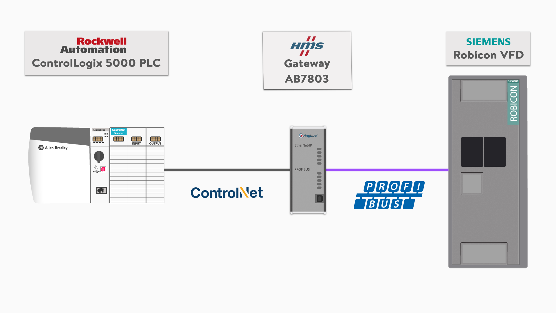
In Part 1, we have addressed how to configure the communication between ControlLogix 5000 PLC and HMS Anybus gateway using ControlNet network media with CIP protocol.
In Part 2, we discussed how the HMS gateway was set up as a PROFIBUS Master to communicate and control the slave Robicon VFD using PROFIBUS protocol. The gateway is a device for converting or translating ControlNet CIP protocol to Siemens PROFIBUS protocol.
In Part 3, we started the configuration of the Siemens VFD properties as the PROFIBUS Slave in the Siemens Starter software, to operate a motor driving feed water pump.
In Part 4, this article, we will pick up where we left off in Part 3 and use the Siemens Starter software to setup the parameters in the VFD.
Configuring the Motor Data in the Siemens VFD Using SINAMICS STARTER Software
In the previous part, I left off in the middle of using the “STARTER” Project Wizard, prior to setting up the Motor and its nameplate data. Now you will learn about configuring motor data in the Siemens Starter software.
Let’s pick up from the step just before the motor configuration where we had configured the drive properties.
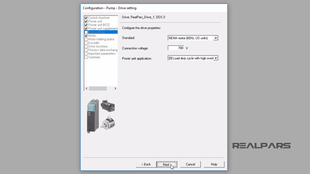
On the Configure the Drive properties display:
– I selected the NEMA motor (60 hertz, US units).
– I set the Connection Voltage to 700 volts.
– I chose Load duty cycle with high overload for the Power unit application.
The reason behind choosing the High overload is that:
– The baseload current for a slight overload is based on a load cycle of 110% for 60 seconds or 150% for 10 seconds.
– The baseload current for a high overload is based on a load cycle of 150% for 60 seconds or 160% for 10 seconds.
I will select the Next button to continue.
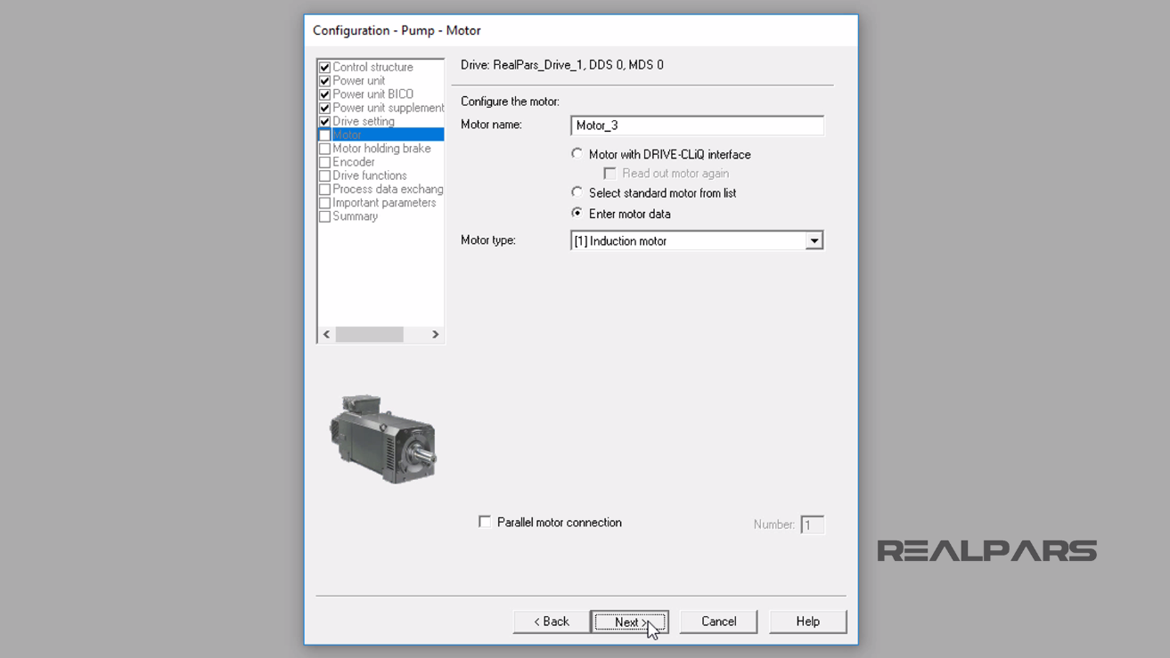
On the Configure the Motor display:
– I will enter the Motor name as, Motor_3.
– I will select the radial button, Enter motor Data.
– I select the Induction Motor for the Motor Type.
Then I click the Next button.
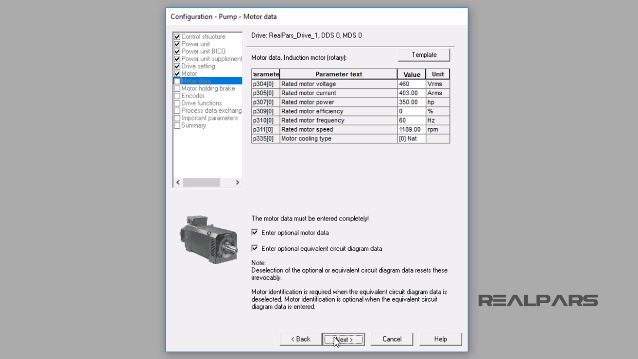
The Motor data configuration window in the Starter software appears.
I will enter:
– Rated motor voltage as 460 Vrms (Volts Root Mean Square)
– Rated motor current as 403 Arms (Amperage Root Mean Square)
– Rated motor power of 350 hp (Horse Power)
– Rated motor efficiency as 0%
– Rated motor frequency of 60 Hz (Hertz)
– Rated motor speed of 1189 rpm (Revolutions Per Minute)
– Motor cooling type of Natural ventilation
I check the boxes for Enter optional motor data and Enter optional equivalent circuit diagram data parameters table and then I will continue by selecting the Next button.
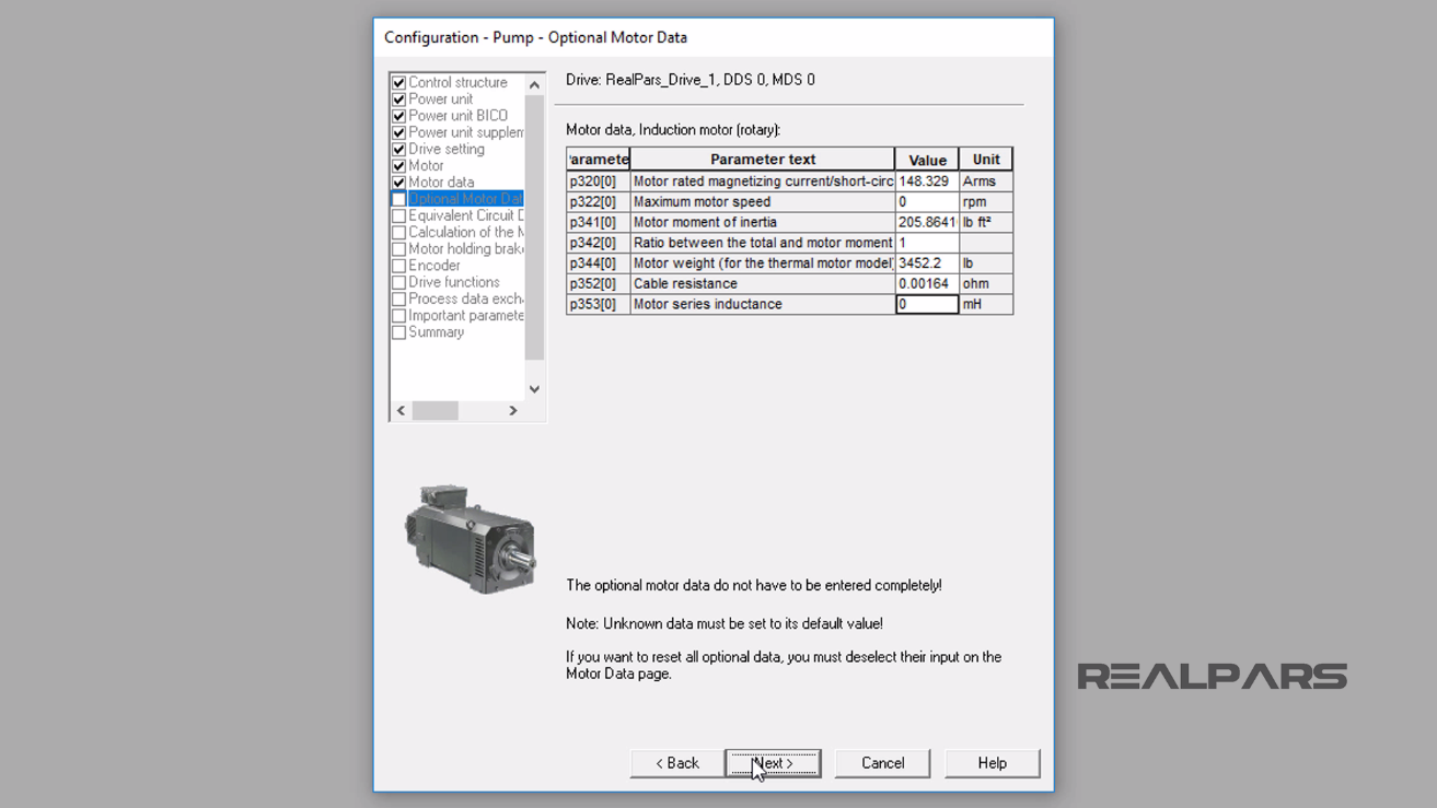
In Optional Motor data display, according to the motor’s datasheet, I will enter:
– Motor rated magnetizing current or short circuit current as 148.329 Arms
– Maximum motor speed of 0 rpm
– Motor moment of inertia of 205.8641 lb ft2
– Ratio between the total and motor moment of inertia of 1
– Motor Weight of 3452.2 lb
– Cable Resistance of 0.00164 Ohm
– Motor series inductance of 0 mH (milli Henry)
I will continue by selecting the Next button.
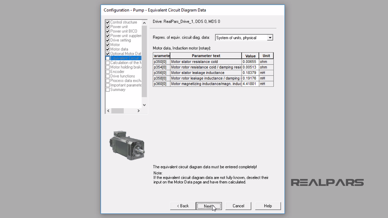
In the Equivalent Circuit Diagram Data display:
– The Representative of Equivalent Circuit Diagram Parameter Data is set as System of units, physical.
– For Motor stator resistance cold value I enter 0.00655 Ohm.
– I will set Motor rotor resistance cold/damping resistance value to 0.00513 Ohm.
– For Motor stator leakage inductance I enter 0.18379 mH.
– The Motor rotor leakage inductance should be set to 0.19176 mH.
– I will set the P360[0] parameter to 4.41801 mH.
I will continue by selecting the Next button.
The Calculation of Motor/Controller data display appears.
I will select the No calculation radial button and continue by selecting the Next button.

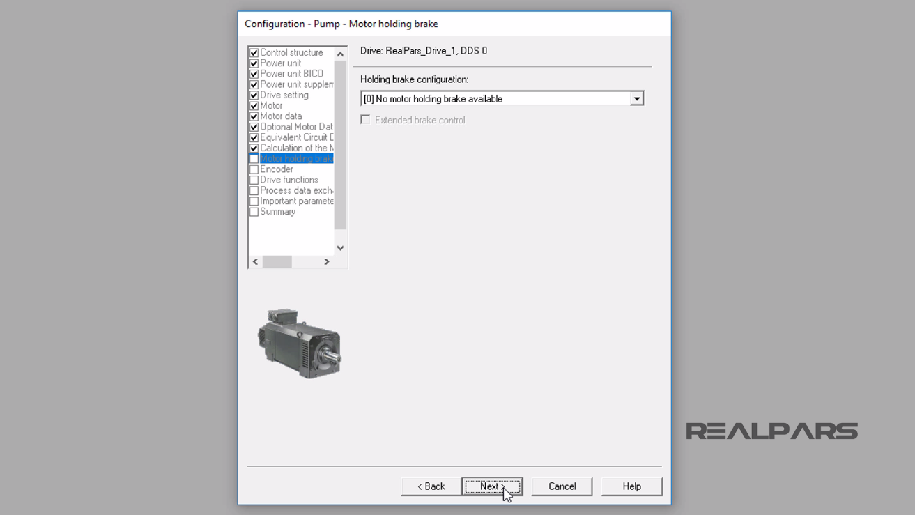
The Motor holding brake display appears.
I select the No motor holding brake available for Holding brake configuration and continue by selecting the Next button.
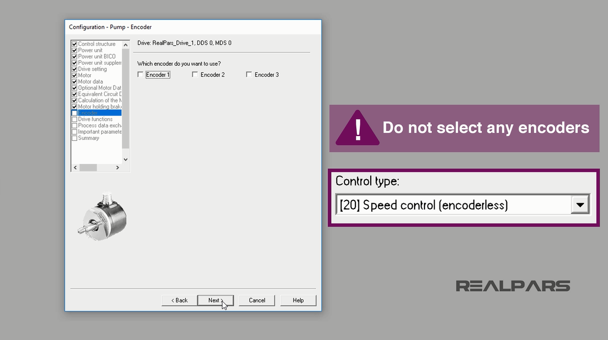
In the Encoder display, I do not select any encoders for this example application, as I chose at the beginning of the configuration not to use any feedback.
I will continue by selecting the Next button.
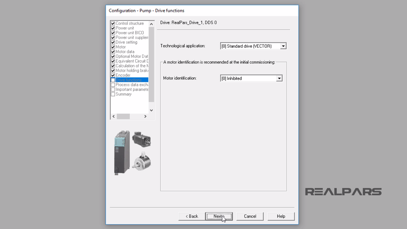
Now, the Drive functions display appears.
– Under the Technological application dropdown menu, I select Standard drive [VECTOR].
– For Motor identification, I select Inhibited.
Vector is chosen because in this configuration the type of motor used does not use an encoder for feedback.
I continue by selecting the Next button.
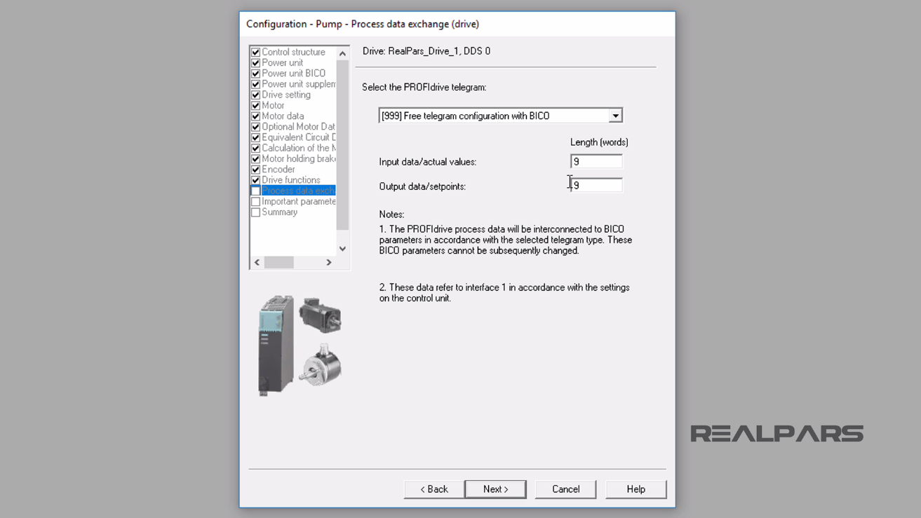
The Process data exchange (drive) display appears.
– Select Free telegram configuration with BICO as the PROFIdrive telegram.
– I will use a length of 9 words for both Input data (actual values) and Output data (setpoints).
Ok, let’s pause the configuration of the VFD in Siemens Starter and define the Free Telegram and the acronym BICO.
What is Free Telegram?
In the Process data exchange (drive) display, I selected a Message frame to use for the communication.
This selection allows for pre-defined standard message frames for various PROFIdrives.
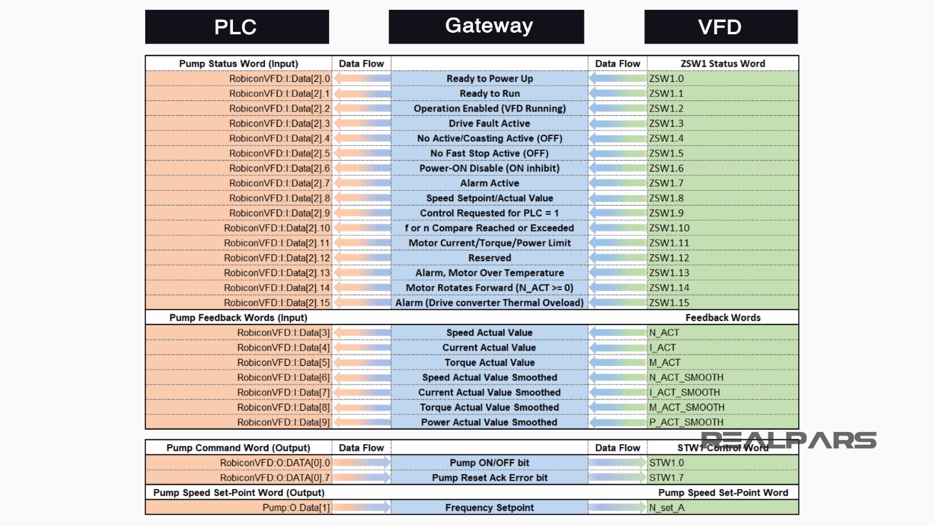
The free message frame selected allows configuration to compile our own message frames using specific wired IO.
This wiring can be referred to in Part 2 of this lesson, shown here as a refresher.
What is Binector Connector Technology (BICO)?
Every drive contains a large number of interconnecting input and output variables and internal control variables.
BICO or Binector Connector Technology is a technology with Siemens VFD drives allows the drive to be adapted to a wide variety of requirements.
Digital and analog signals can be connected by means of the BICO parameters and are identified by the prefix BI, BO, CI or CO in their parameter name.
A binector is a digital (binary) signal without a unit which can assume the value 0 or 1.
A connector is a digital signal in 32-bit format. It can be used to emulate words (16 bits), double words (32 bits) or analog signals.

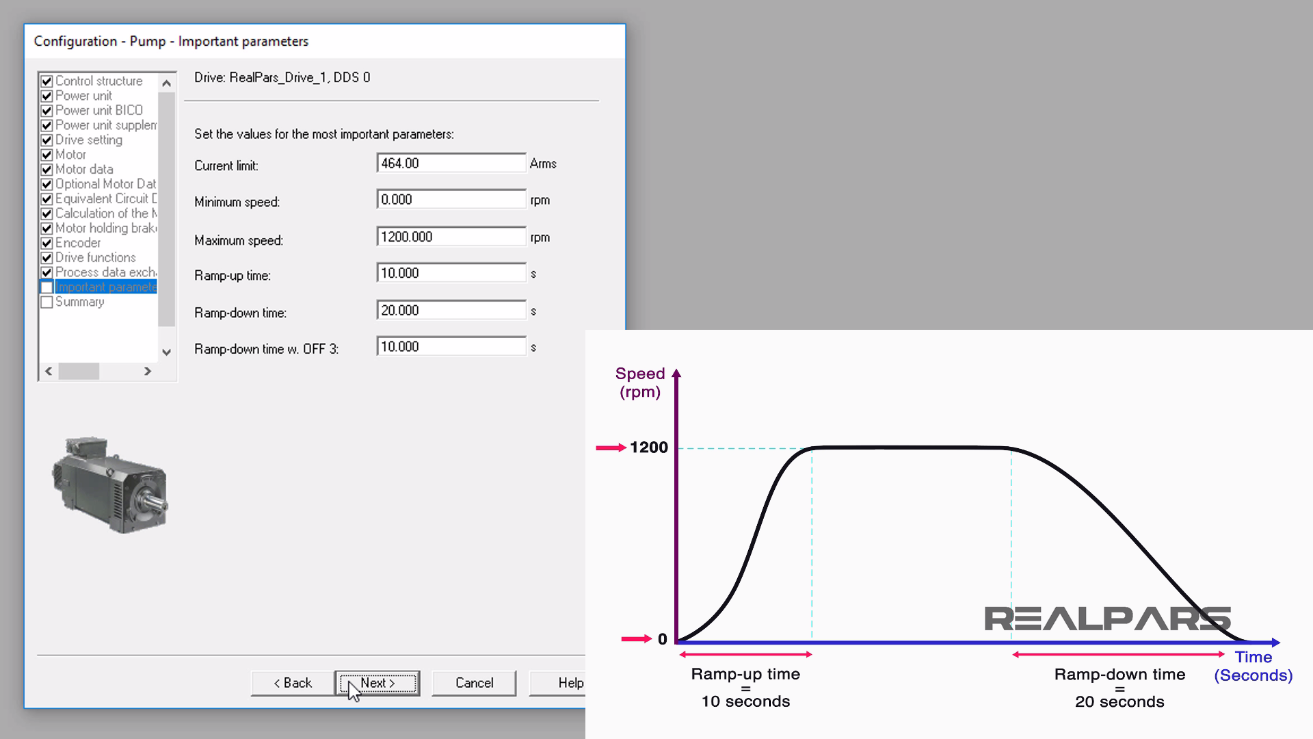
After selecting the Next button in the Process data exchange (drive) window, the Important parameters display appears.
According to the motor’s datasheet, I will set:
– Current limit to 464 Amps
– Minimum speed to 0 rpm
– Maximum speed to 1200 rpm
– Ramp-up time to 10 seconds
– Ramp-down time to 20 seconds
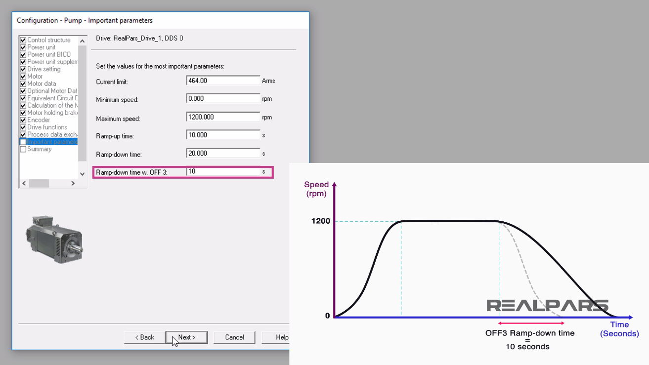
– Ramp-down time w. OFF 3 to 10 seconds
The Ramp-down time w. OFF 3 parameter is effective from the maximum speed down to the motor standstill providing an overall time to decelerate and stop.
I will continue by selecting the Next button and the Pump Configuration Summary display will appear.
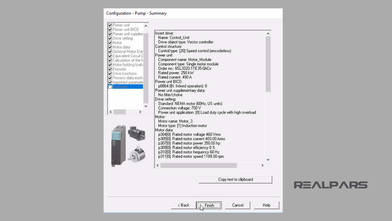
I can select the Finish button to continue, but for now, we will stop with this segment of the lesson in the Siemens Starter Software.
In the next lesson, Part 5 and the final part of this series of lessons, we will continue with the VFD configuration using the Siemens Starter commissioning software and jump into configuring the communication data.
I hope you have enjoyed learning what will support you in your upcoming project.
Got a friend, client, or colleague who could use some of this information? Please share this article.
How to Control a VFD with a PLC – Part 1
How to Control a VFD with a PLC – Part 2
How to Control a VFD with a PLC – Part 3
How to Control a VFD with a PLC – Part 5