

One of the most challenging parts of any automation project is getting all of the devices to communicate with each other.
As many of you know, trying to get two devices from two different manufacturers to communicate can be the source of a lot of headaches and issues on an otherwise smooth project.
In this article, I will show you how easy it is to connect an RS PRO HMI to an S7-1200 or an S7-1500 PLC over an Ethernet network.
In the next 10 minutes, we will configure and program a PLC in TIA Portal, create and configure an HMI application in piStudio, and test the connection between the two devices.
This article is brought to you in partnership with RS, a global omnichannel provider of industrial product and service solutions. Follow this link to learn how they can help bring value and efficiency into every step of your process!
Let’s get started by configuring the PLC in TIA Portal.
PLC configuration
In TIA Portal, I have created a new project and added an S7-1211 PLC to the project. I have used an S7-1211 PLC because that’s what I have available in my lab. If you are following along at home, you can use any type of S7-1200 or S7-1500 PLC.
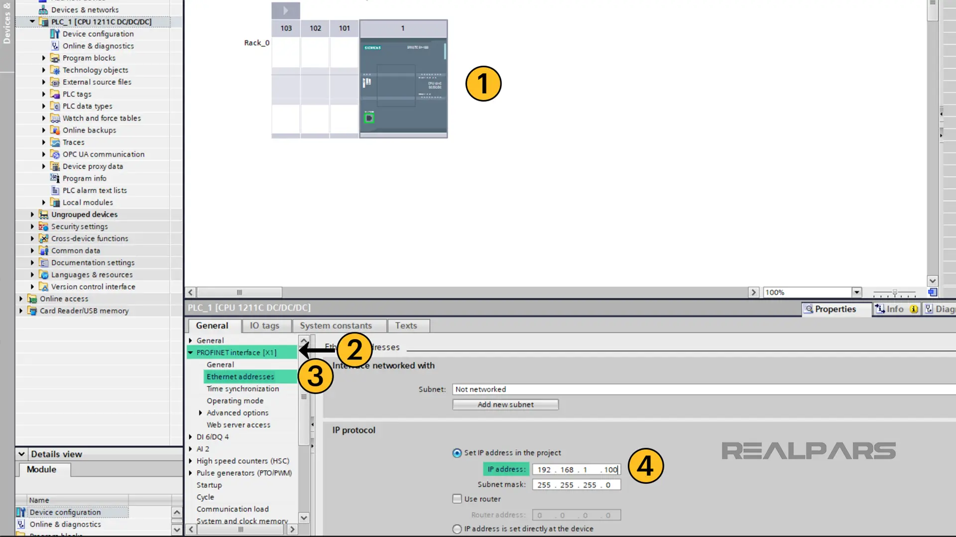
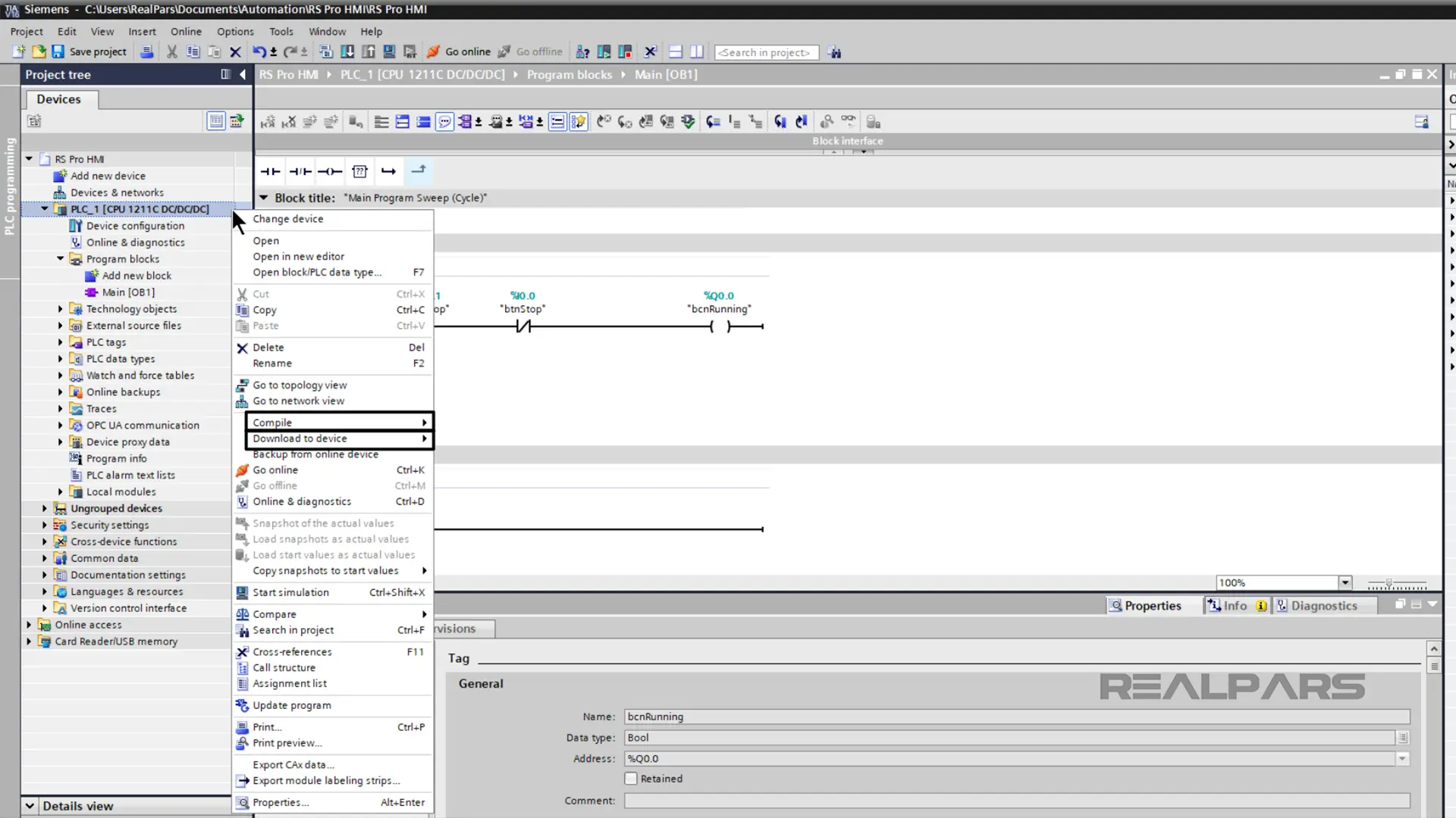
In the Devices & Networks Editor, I select the PLC to access the PLC’s property configuration.
Since the PLC will be communicating with the HMI over an Ethernet-based network, I need to configure an IP address for the PLC which is on the same subnet as the HMI.
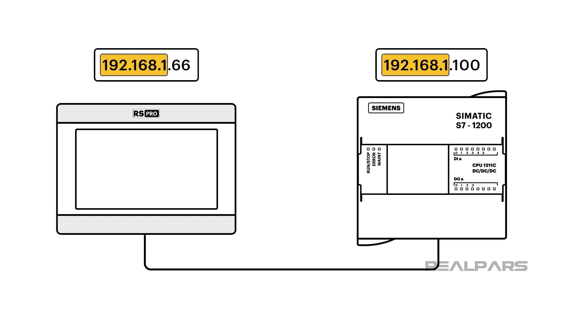
To configure the IP address of the PLC, I scroll down to PROFINET interface [X1] > Ethernet addresses and assign the IP address 192.168.1.100 to the PLC.
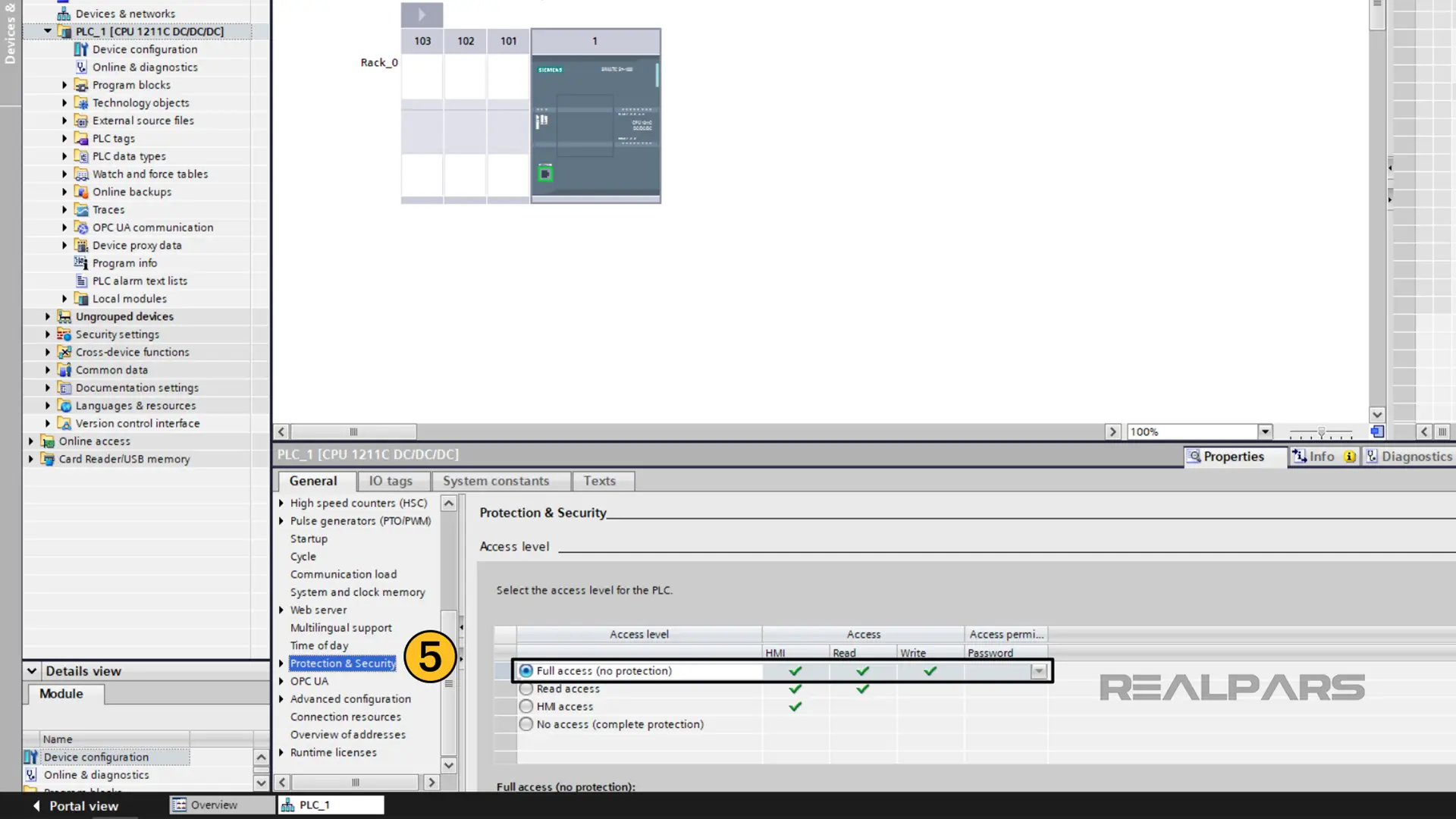
As well as configuring the IP address for the PLC, I have to allow external devices to access the PLC’s data, and enable the communication protocol that is used to exchange data between the PLC and HMI.
To do this, I scroll down to the Protection and Security section of the PLC’s properties.
In this folder, I set the access level to Full Access. This allows external devices to read and write all of the data in the PLC.
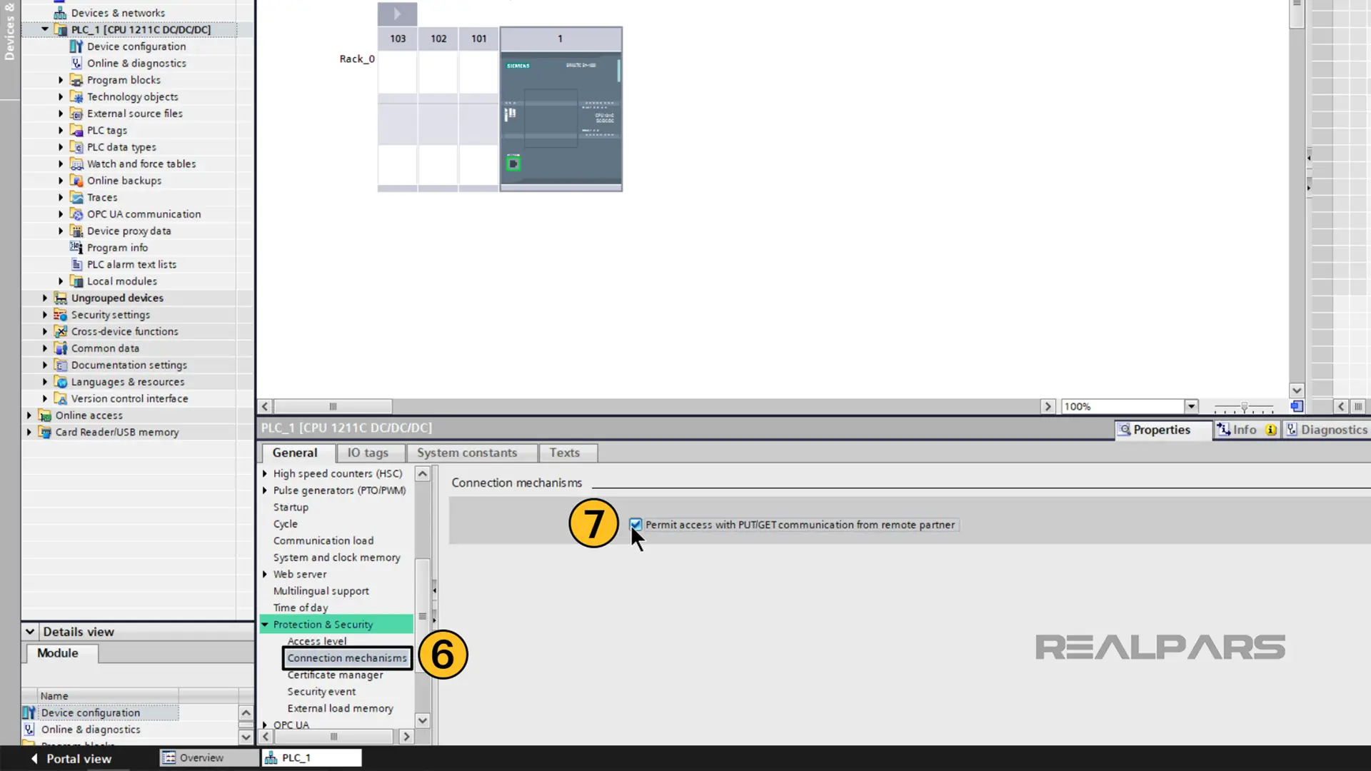
Finally, I need to enable PUT/GET communication in the PLC. This is the communication protocol that is used for communications between the PLC and the RS PRO HMI.
To enable PUT/GET communication, I open the Connection mechanisms page and activate the Permit access with PUT/GET communication from remote partner option.
Now that the PLC is configured, we can write some simple logic that we will use to test the HMI communication later on.
PLC programming
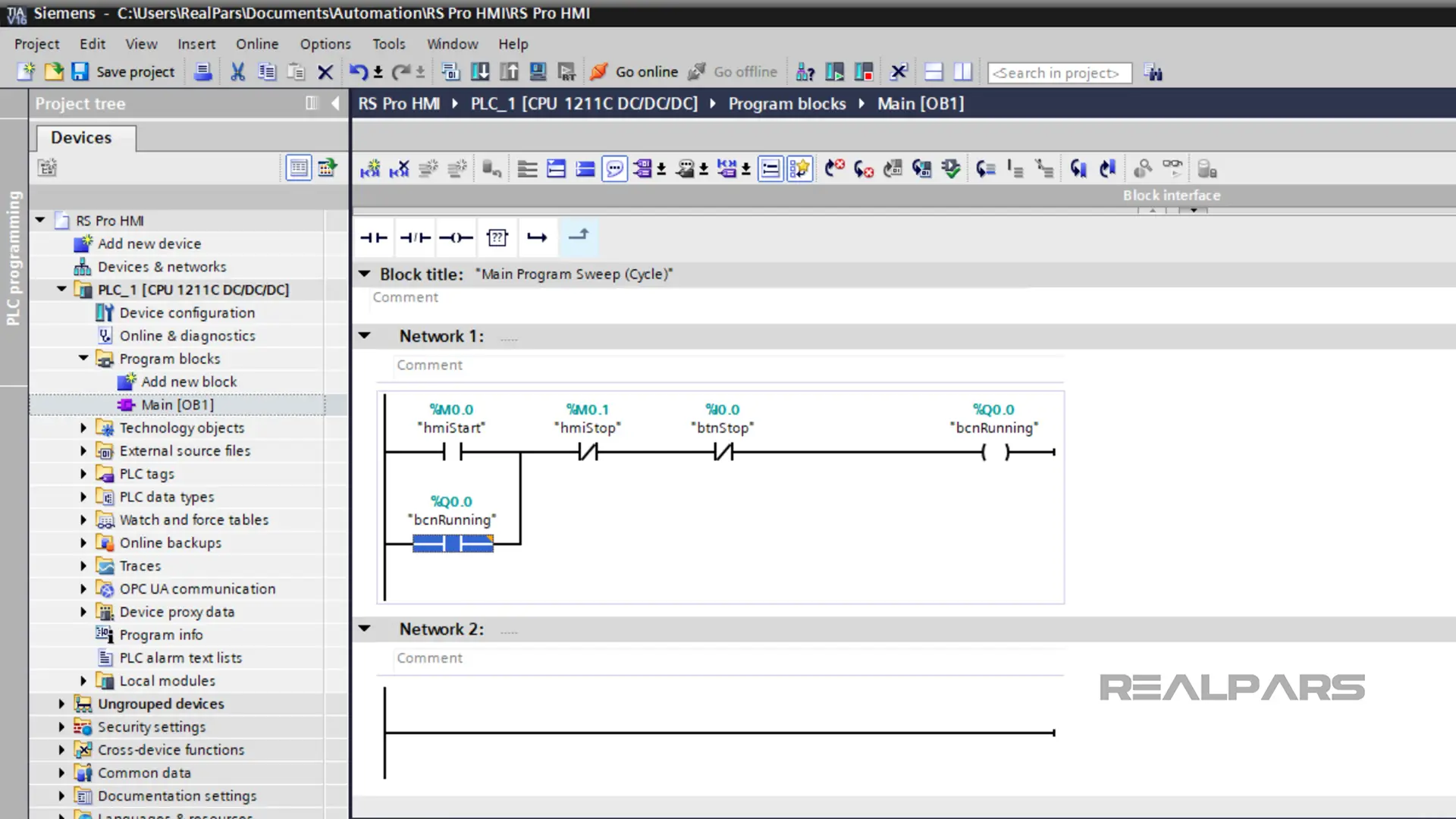
I double-click on the Main OB to open the object.
Once opened, I program a simple seal-in circuit as shown here with one permissive and two interlock conditions.
Once the programming is done, I can define the tags for my project. To show how an RS PRO HMI can interact with different types of tags in an S7 PLC, we will use a combination of Memory, Global Output, and Global Input tags.
In this example, my process can be started or stopped from the HMI using the tags hmiStart and hmiStop. The addresses for these tags are M0.0 and M0.1 respectively.
The process can also be stopped with a physical stop button. This stop button is wired to the PLC’s input I0.0 and I create a tag for this input called btnStop.
Finally, when the process is running the PLC turns on the physical output Q0.0 which is associated with the tag bcnRunning.
Once I have finished configuring the logic, I compile my project and download it to the PLC.
At this point, we have finished programming the PLC and we can turn our attention to piStudio, the development environment for RS PRO HMIs.
Configure the HMI
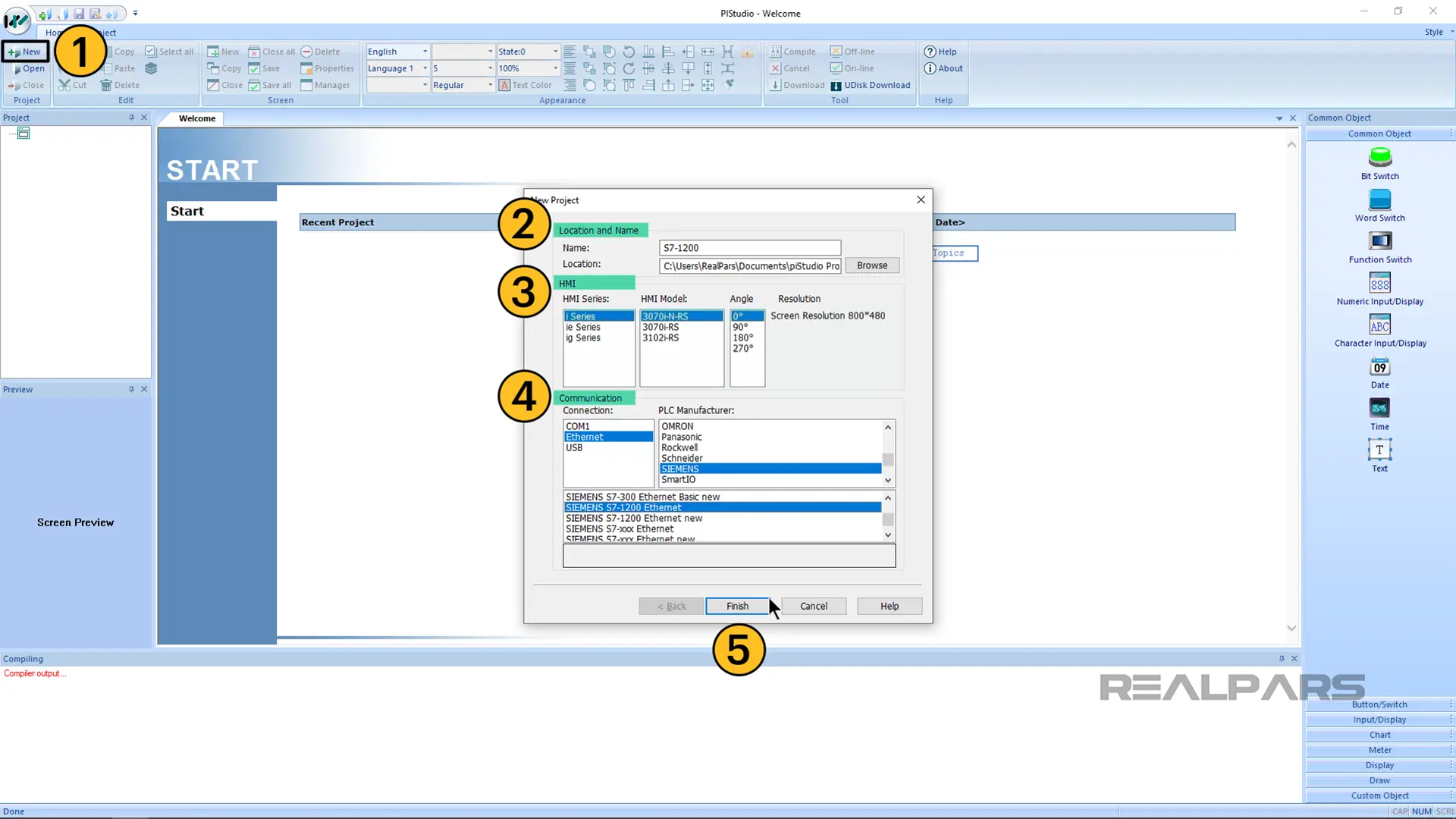
I create a new project, in piStudio.
In the new project dialog, I specify the name of the project, the type of RS PRO HMI used, and the communication configuration. In this example, I want to use the Ethernet connection to communicate with a Siemens S7-1200 PLC.
Once these settings are configured, I click on Finish to create the project.
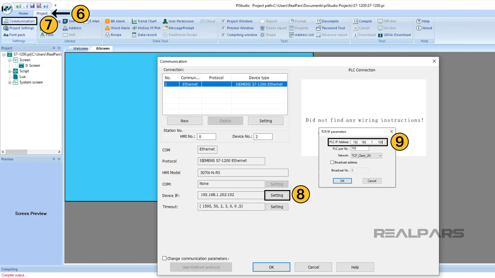
In the project, I need to specify the IP address of the PLC that the HMI will be communicating with. I do this in the project’s communication configuration.
To open the communication configuration, activate the Project tab in the toolbar and click on Communication.
In the Communication dialog box, click on Setting beside the Device IP field to set the IP address for the PLC that the HMI will communicate with. Notice that I am only updating the IP address and I leave the other options at their default values.
When the configuration is done, I click OK on both dialog boxes to store the configuration and close the dialogs.
We also need to specify the IP address of the HMI.
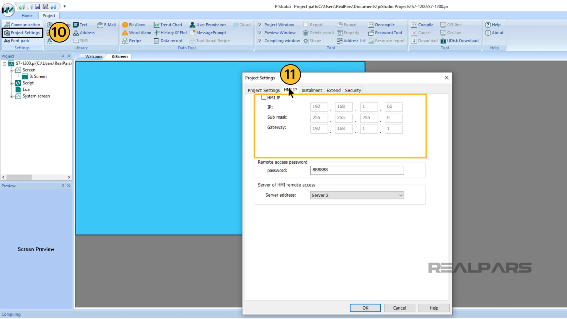
To do this, click on Project Settings and configure the IP address of the HMI in the HMI IP tab.
Now that the HMI is configured, we can build our HMI application.
Build the HMI application
Adding objects to the HMI screen
We can add objects to the HMI screen by dragging them from the toolbox and dropping them on the canvas.
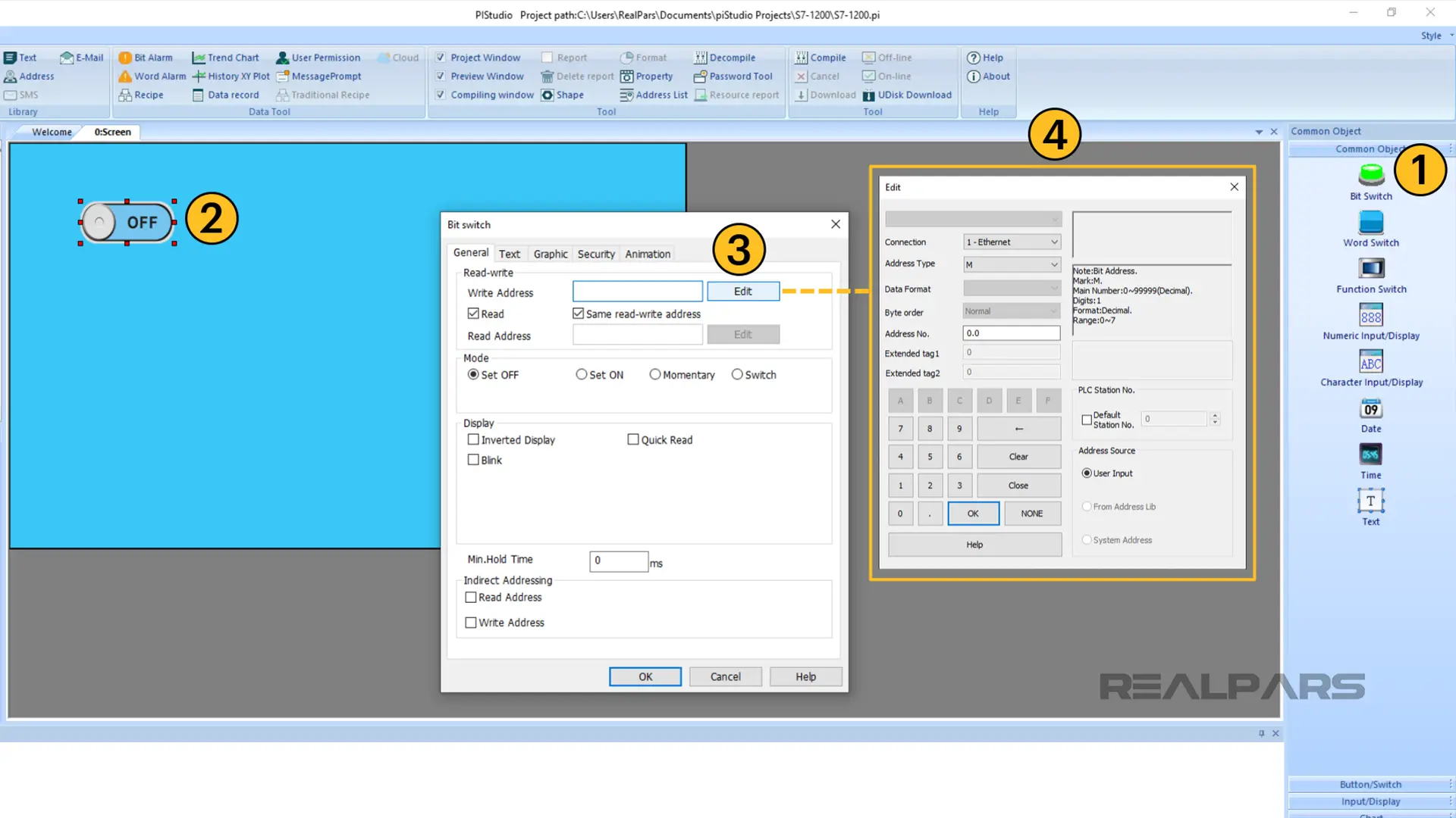
I’ll start by adding a Bit Switch to the canvas as shown here.
Once an object is placed on the canvas, I can double-click on the object to open its configuration menu.
For the Bit Switch object, I need to configure what tag in the PLC it writes to. To specify a tag, I can click on the Edit button beside the Write Address field.
In the dialog box that opens, I set the PLC tag’s address as M0.0, which was the address of the hmiStart tag.
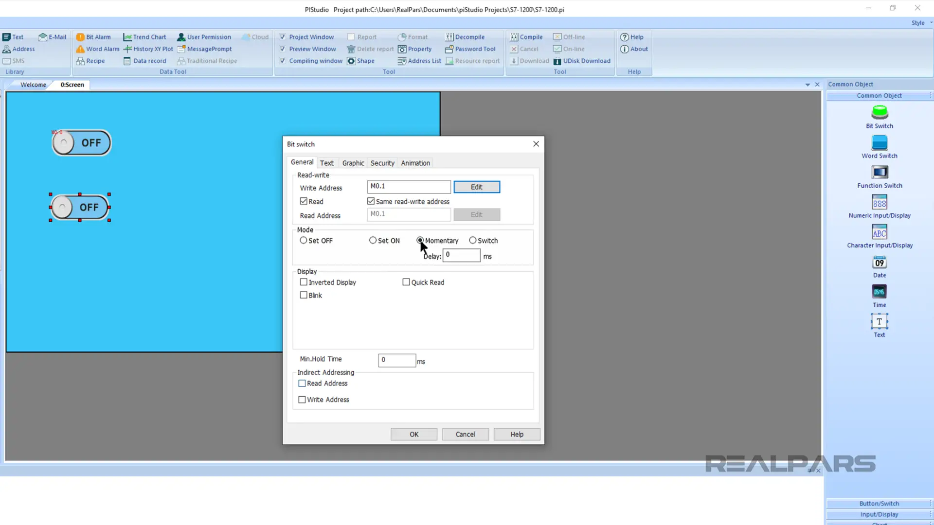
I click OK twice to store the configuration and repeat the process to add a second Bit Switch object for the hmiStop tag with the address M0.1.
I also need to specify the mode of this Bit Switch. Under Mode, I select Momentary. When a Bit Switch is operating in Momentary mode, it writes the value True to its associated tag while the switch is active.
As well as controlling the value of tags by writing to them from the HMI, we can also visualize the status of tags by reading their values.
From the toolbox, I add a Bit Lamp object to visualize the status of a Boolean tag in the PLC.
Once again, I can double-click on the object to open its configuration dialog and I can define the address of the tag that the object will read. Here I am reading from the address I0.0, which was the address of the physical stop button.

I repeat this process to add another Bit Lamp that reads from the address Q0.0, which was the output that turns on when the process is running.
Adding text labels
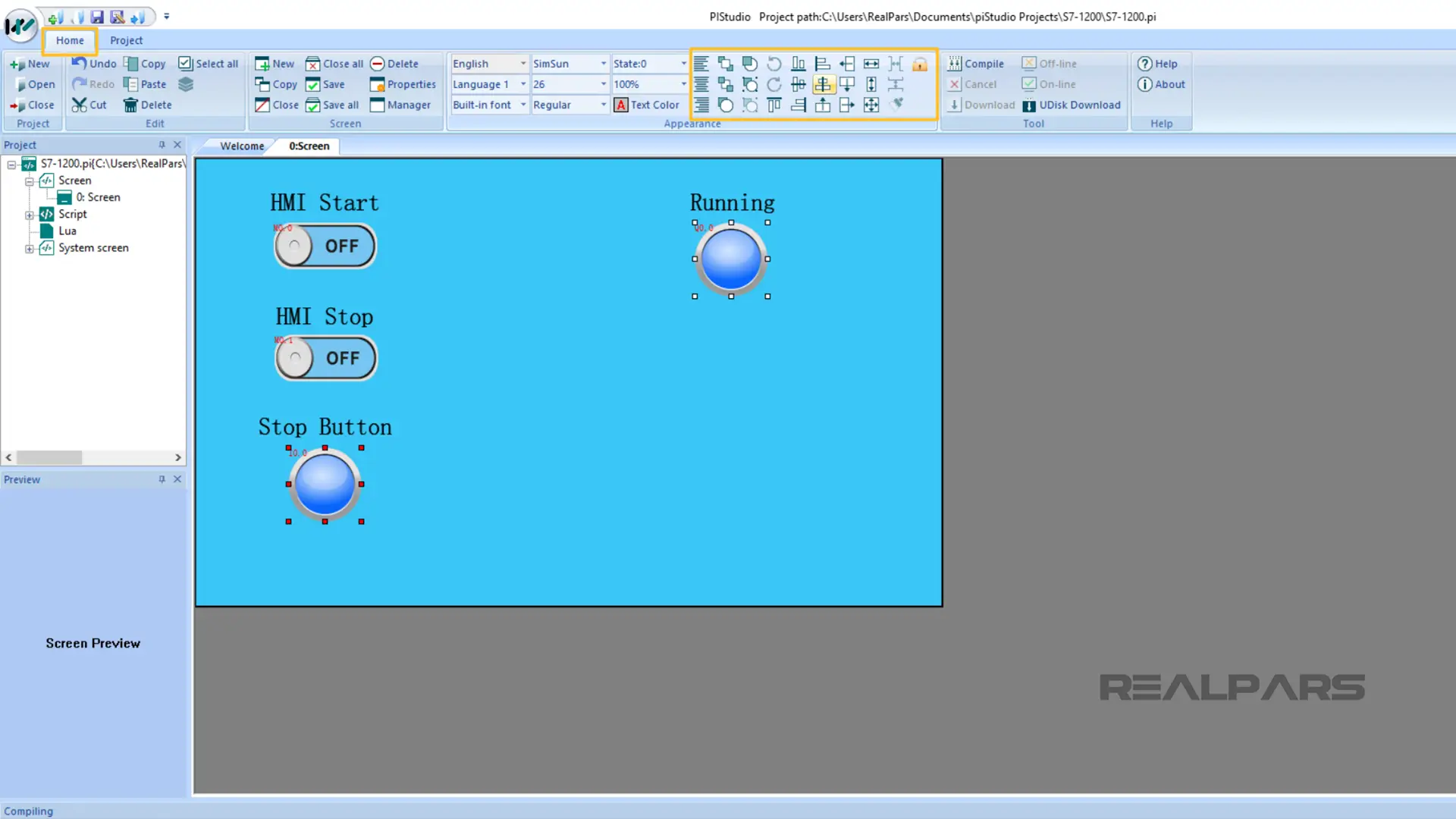
At this stage, our HMI is almost finished. The last thing I will do is add some text labels to explain what the objects on our HMI do.
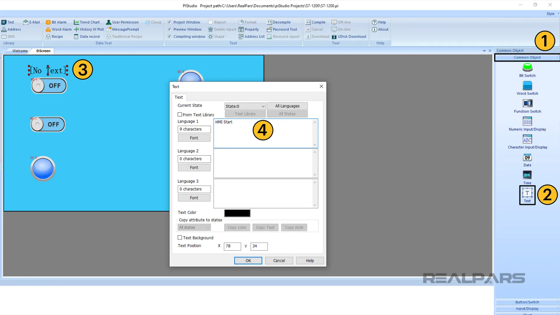
To do this, I activate the Common Object folder in the toolbox and drag a Text object onto the canvas above the hmiStart Bit Switch.
I double-click on the object to open its configuration dialog and update the text to HMI Start.
I copy and paste this text object to add labels to the other objects on the canvas.
If I want, I can use the positioning tools available on the toolbar to position and align the objects on the canvas as shown here.
Now that the HMI development is done, we can compile the HMI using the Compile button on the toolbar and download the application to the HMI.
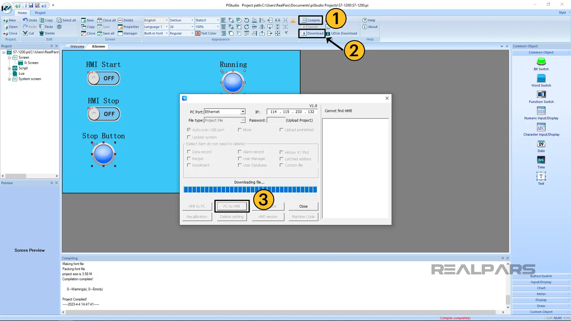
Once the application is downloaded, we can test the communication to make sure that everything is working as expected.
Test the communication
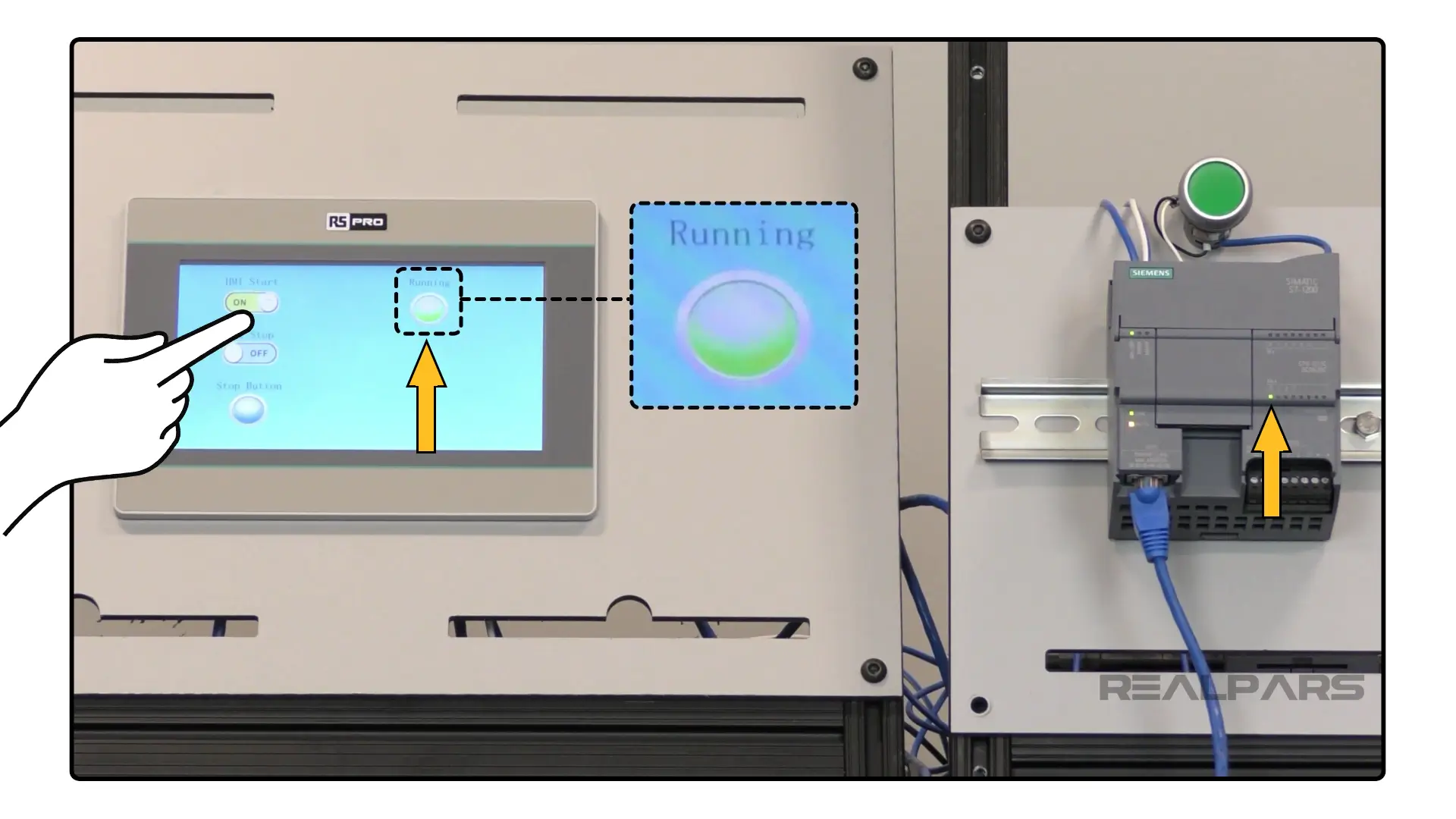
On my HMI, I turn on the HMI Start bit switch. When this switch is on, it writes the value True to the hmiStart tag in the PLC and the output bcnRunning becomes True.
I can see that the tag bcnRunning is True because the appearance of the Running Bit Lamp has been updated.
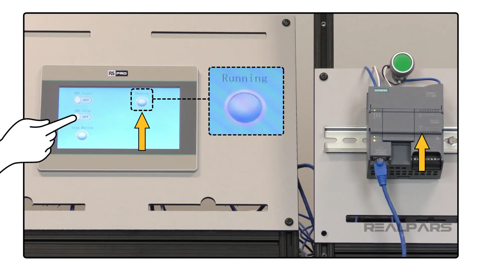
I turn off the HMI Start Bit Switch and activate the HMI Stop Bit Switch. This writes the value True to the hmiStop tag which is an interlock for the process.
As expected, the bcnRunning tag becomes False and we can see that the process has stopped from the appearance of the Running Bit Lamp.
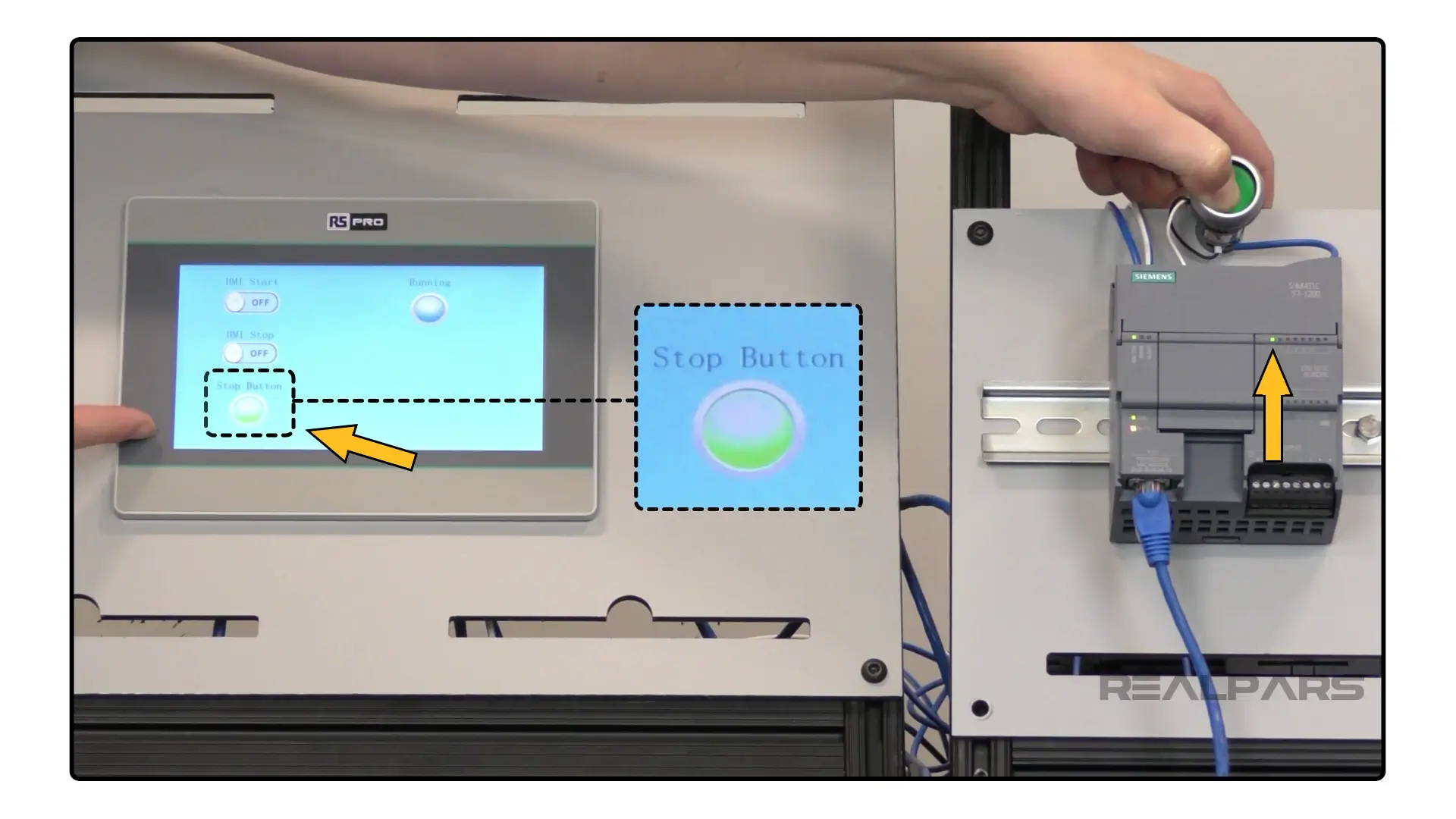
Finally, I can toggle the physical input I0.0 of the PLC. I can see the value of the physical input changing from the Stop Button Bit Lamp on the HMI.
At this point, we can confidently say that the communication between the PLC and HMI is working.
Wrap-Up
In this article, I showed you how easy it is to set up communications between a Siemens S7-1200 PLC and an RS PRO HMI using TIA Portal and piStudio.
Specifically, we learned how to specify an IP address for the PLC, configure the PLC’s access level, and enable PUT/GET communication.
Once the PLC configuration was complete, we learned how to configure the IP address of the PLC that the HMI communicates with and how to map HMI objects to tags in the PLC.
If you need guidance on which products best fit your needs, RS is a great solutions partner who offers application consulting services. The RS Engineering team and Technical Solutions Center are ready to support you with your project needs.
Want to dive into the world of Siemens PLC programming? We’ve got you covered! Enroll in the RealPars course – it’s free and super easy to follow.

RealPars and RS Americas are offering a limited-time opportunity for a free industrial consultation service available to those located in the US, Canada, or Mexico. Boost productivity, reduce downtime, and drive innovation in your operations.