

In the world of industrial automation, a Factory Acceptance Test or FAT is simply a test for a newly manufactured control system that takes place at your factory or your workshop before you ship the control panel to the customer.
With a Factory Acceptance Test, you make sure that everything works properly before you deliver a control cabinet to a customer.
Now, don’t let this long-looking technical phrase scare you. If you look at your everyday life, you actually do a Factory Acceptance Test or FAT several times during the day.
For example, when you’re done writing something on a simple Google Doc, you actually review the document once or maybe twice, depending on how important it is, before sending it to a friend or colleague.
This is actually an acceptance test, done by you, on your computer before the document is sent.
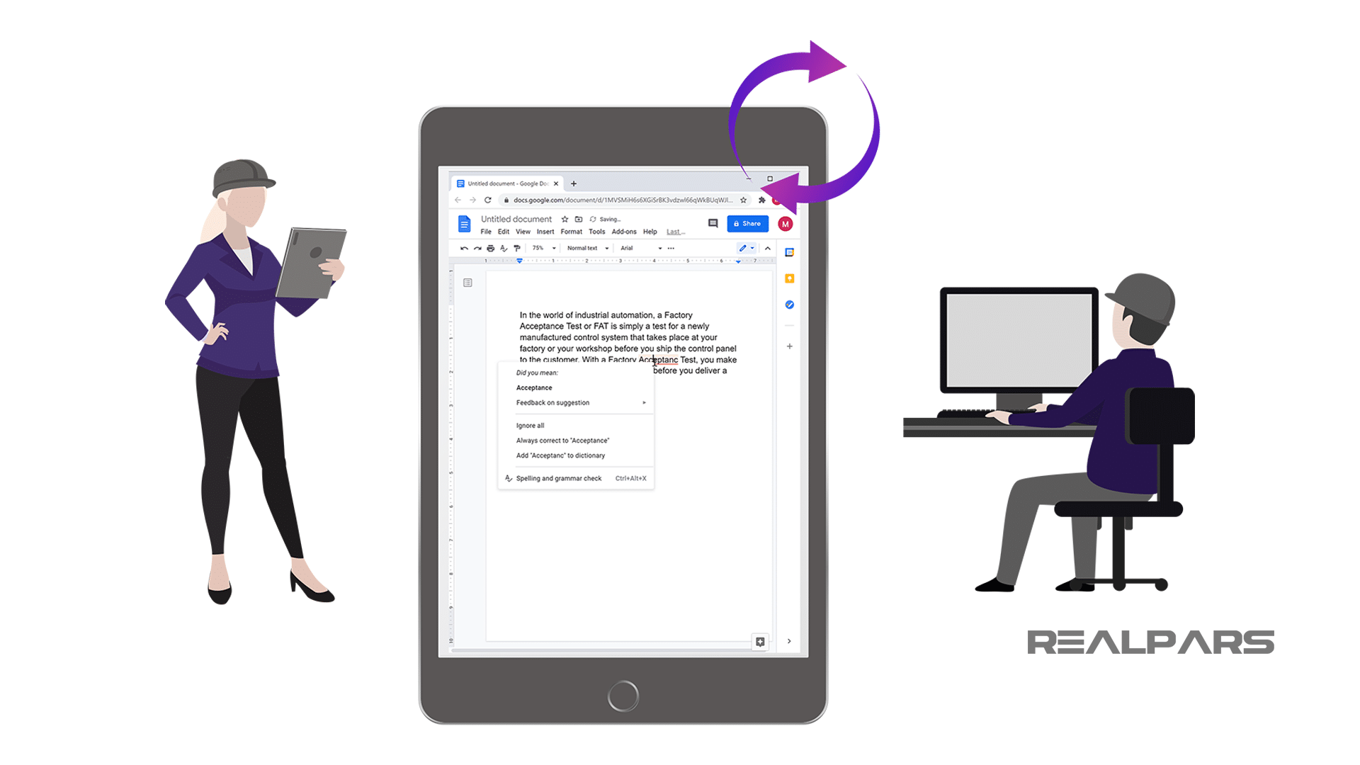
This is what I like to call a Document Acceptance Test which is Actually a made-up name as I don’t think there is such thing as Document Acceptance Test but the point that I like to make to you as an automation engineer is that Factory Acceptance Test is not a complicated concept and we do these acceptance tests several times a day working on other tasks.
FAT example
Now that you have a good idea about the concept and feel comfortable with it, let’s explore FAT a bit further through a practical example.
Let’s say that you are a company that designs and implements industrial control systems.
These control systems often come in the form of a control panel built into a control cabinet.
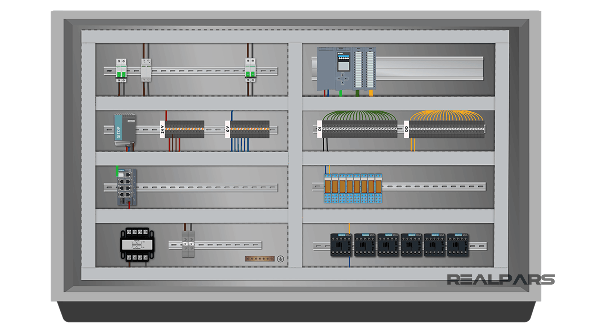
You’ve built a control panel and now it’s ready to ship to the customer. But before you ship it you want to make sure that everything works properly. The last thing you want is to ship it to the customer’s site only to find out that things are not quite working the way they should.
Consequently, you will have to spend countless hours at the client’s site solving issues that you could have easily taken care of before shipping the control panel. So, as the name suggests, a FAT is completed at the factory.
Now you may be wondering, where should I start? What do I need to test? Well, I will show exactly that through a step-by-step example.
But before doing this I need to give you a warning. Electricity is dangerous and can be fatal. You should be qualified before doing any electrical work. Alright, let’s get started.
Step 1) Power the control panel
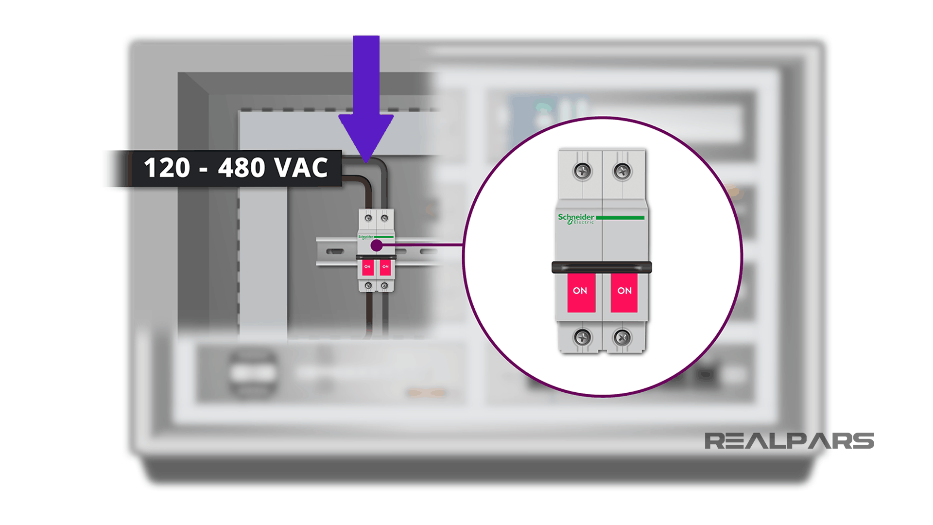
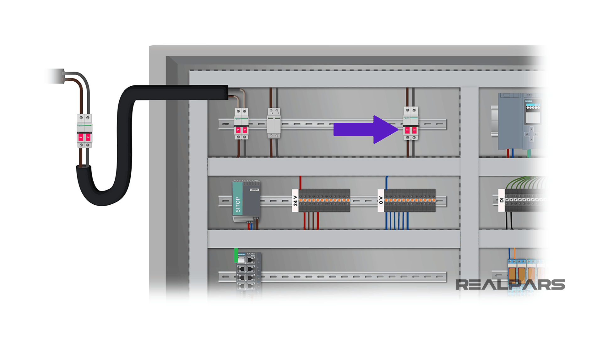
As the first step, you need to connect the power to your control cabinet and turn it on. We have a main circuit breaker for every control panel. This is where the power comes into the control panel for all of the devices.
To let the electricity come into the panel, you need to connect the power to the topside of the circuit breaker. This is a wire that comes from outside of the panel.
You connect it to the circuit breaker only for testing and once you are done and want to ship the cabinet, you simply disconnect the wires from the topside of the circuit breaker.
The power that comes into the panel can be anywhere from 480 volts AC to as low as 120 volts AC depending on where you are and the country you are based in.
Once you have the power connected to the topside of the circuit breaker, you can switch it on for the power to flow to the control panel.
Although this seems a very simple process so far, there are two important points that you need to consider when trying to power on your control panel.
Point #1
The circuit breaker generally has a disconnect on the outside of the panel that allows you to shut off the power. Before you want to connect the cable to the main circuit breaker inside the panel make sure that you have disconnected the power using this switch.
Don’t take the hot power into your hand and try to connect it to the circuit breaker. This is dangerous. I have made this mistake a couple of times during my career but I was lucky I did not touch the hot wire.
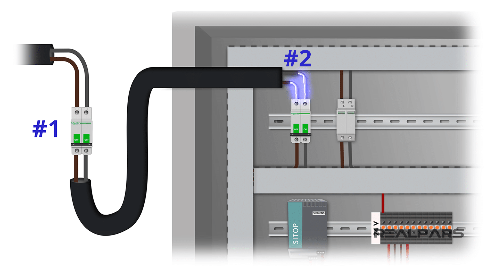
Point #2
The second point to consider here is that when you switch off the circuit breaker, the topside of it will still have power. So, again, before you want to disconnect the power you need to make sure that you have disconnected the power from the outside of the panel.
Step 2) Switch on all the devices in the control panel
Switch on the breakers & the fuses
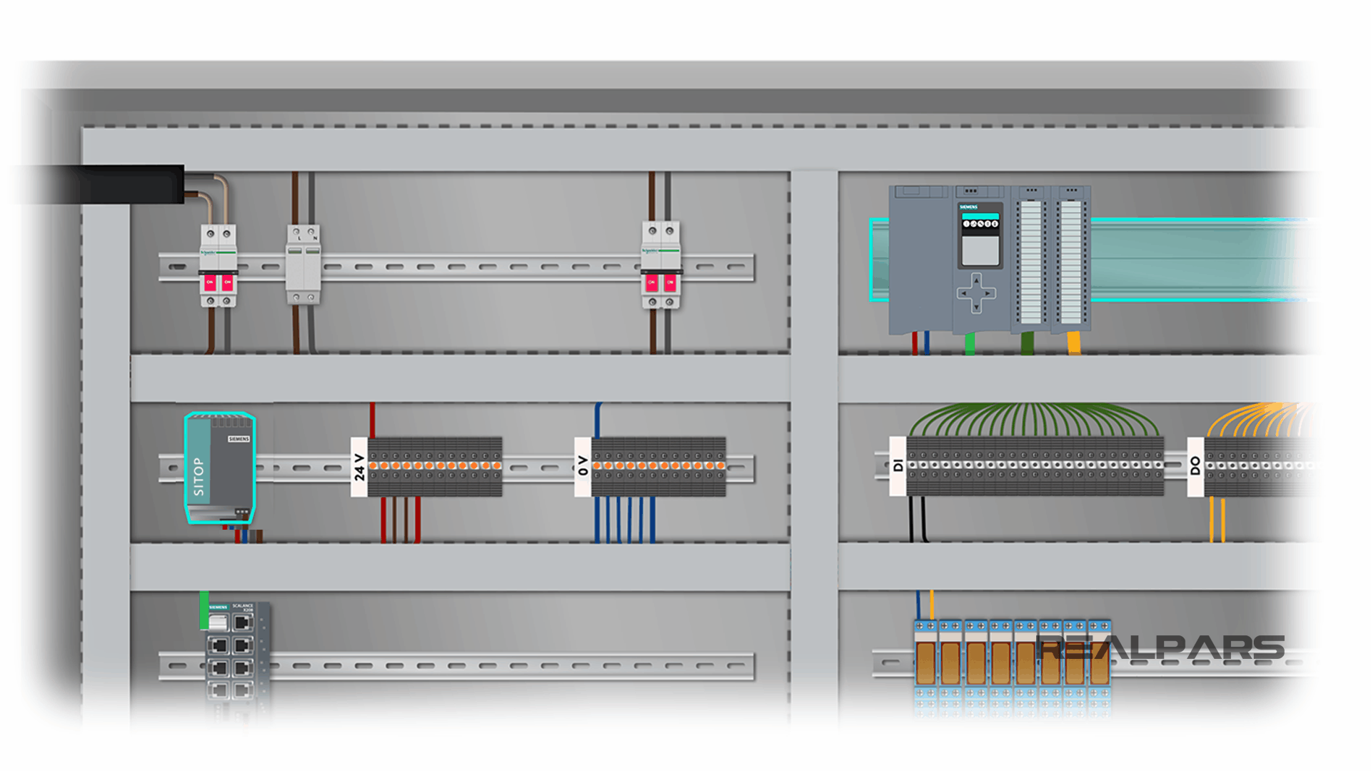
Now that you have connected the power cable to the control panel and switched on the circuit breaker, you also need to switch on any other breakers or fuses that you may have on the way to power the PLC and the other devices.
Switch on the PLC power supply
In the end, I also switch on the PLC power supply as well. The PLC power supply could be installed on the same rack as the PLC or somewhere else on the panel. We may have one, two, or three power supplies on our panel depending on how many devices we need to power on in the control panel. The more devices we have, the more power we need to turn them on.
PLC Digital I/O Test
So you have connected the power to the main circuit breaker and turned on all the devices on your panel. Now let’s move on to the third step.
When performing a FAT for a control cabinet that includes a PLC, like the example we have here, one of the most important things to test is the PLC inputs and outputs.
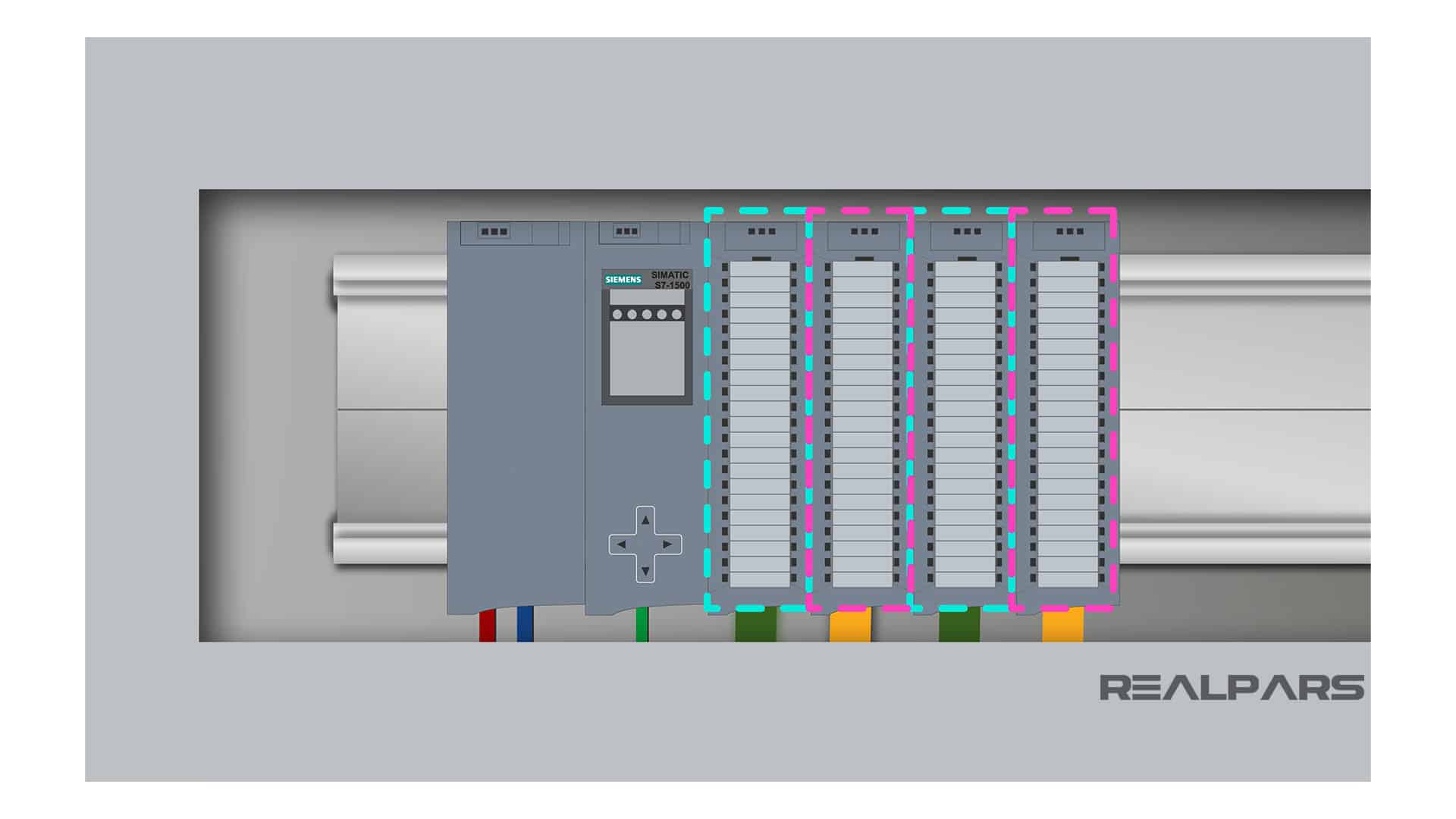
Depending on your application, you may have different input and output cards for your PLC. For this PLC we have a digital input card, a digital output card, an analog input card, and an analog output card.
To do a FAT you need to test each of the PLC inputs and outputs one by one and make sure everything works properly based on the PLC logic.
But you may ask “how can I do this while the control cabinet is still not installed on the site and there are no actual sensors or actuators connected to it?”
The answer to this question is simulated signals. You need to use simulated signals to perform your Factory Acceptance Test. Don’t worry, this is very simple. I will show you how to do that.
You can learn more about signal simulation by reading the article, What is an Instrument Calibrator?.
Step 3) Test the PLC digital inputs
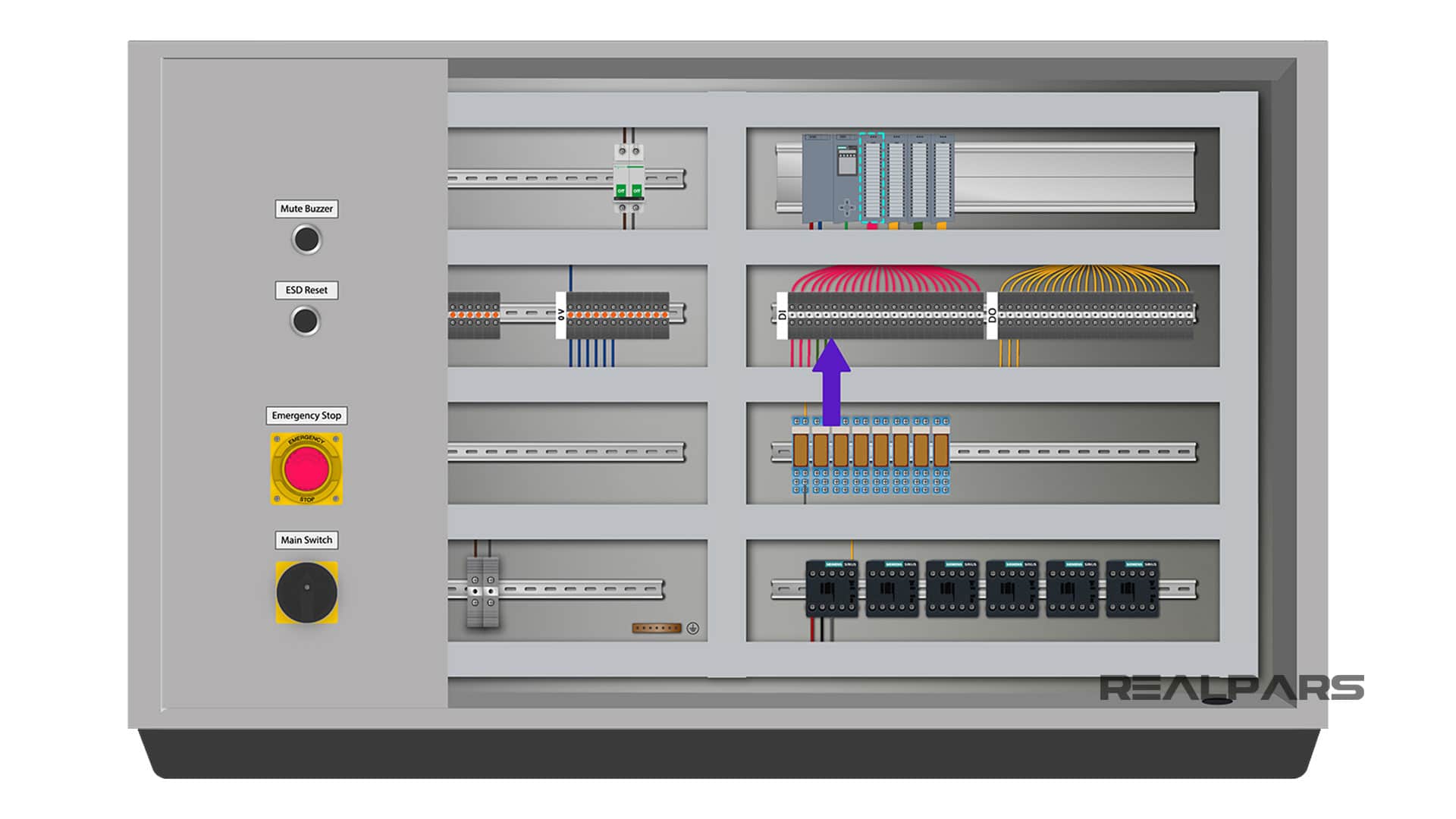
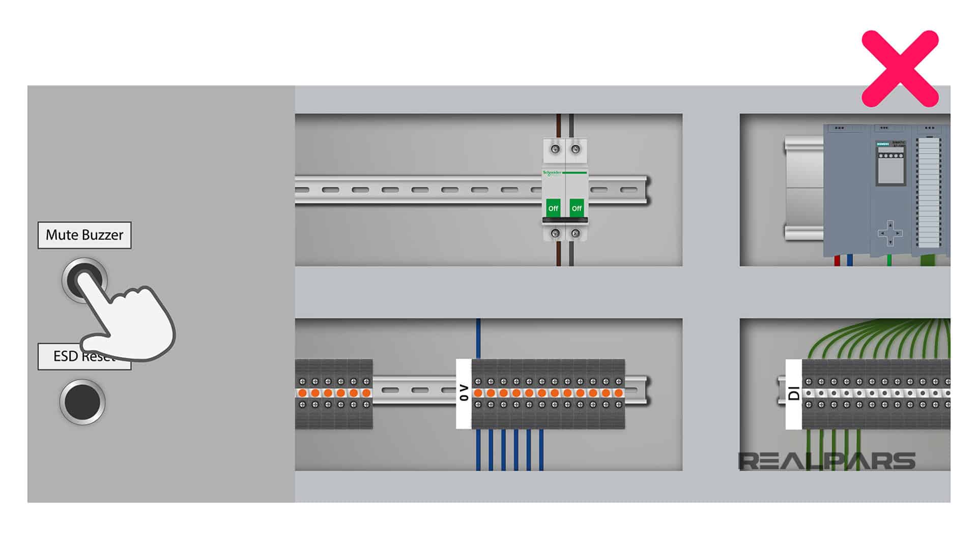
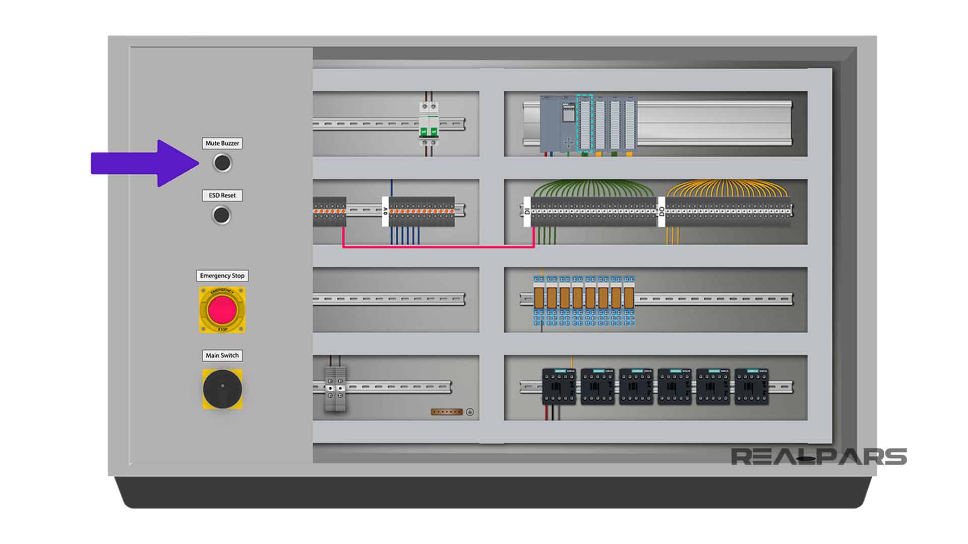
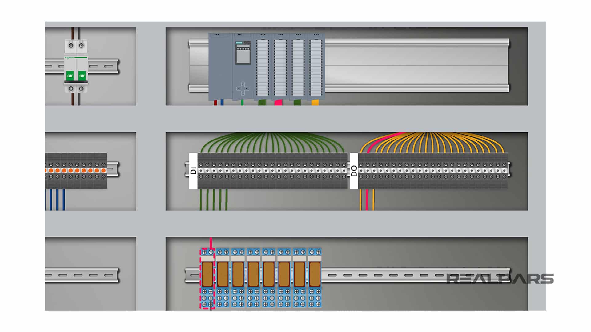
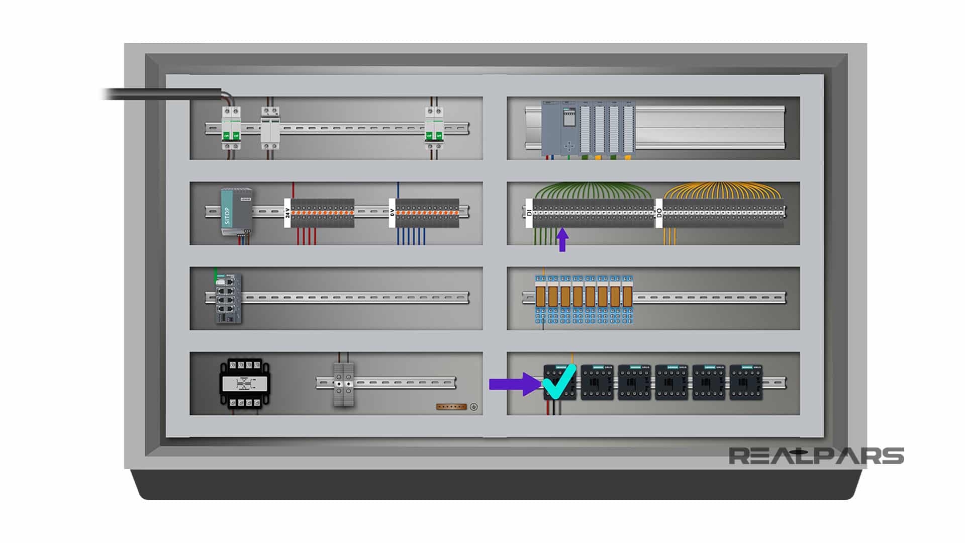
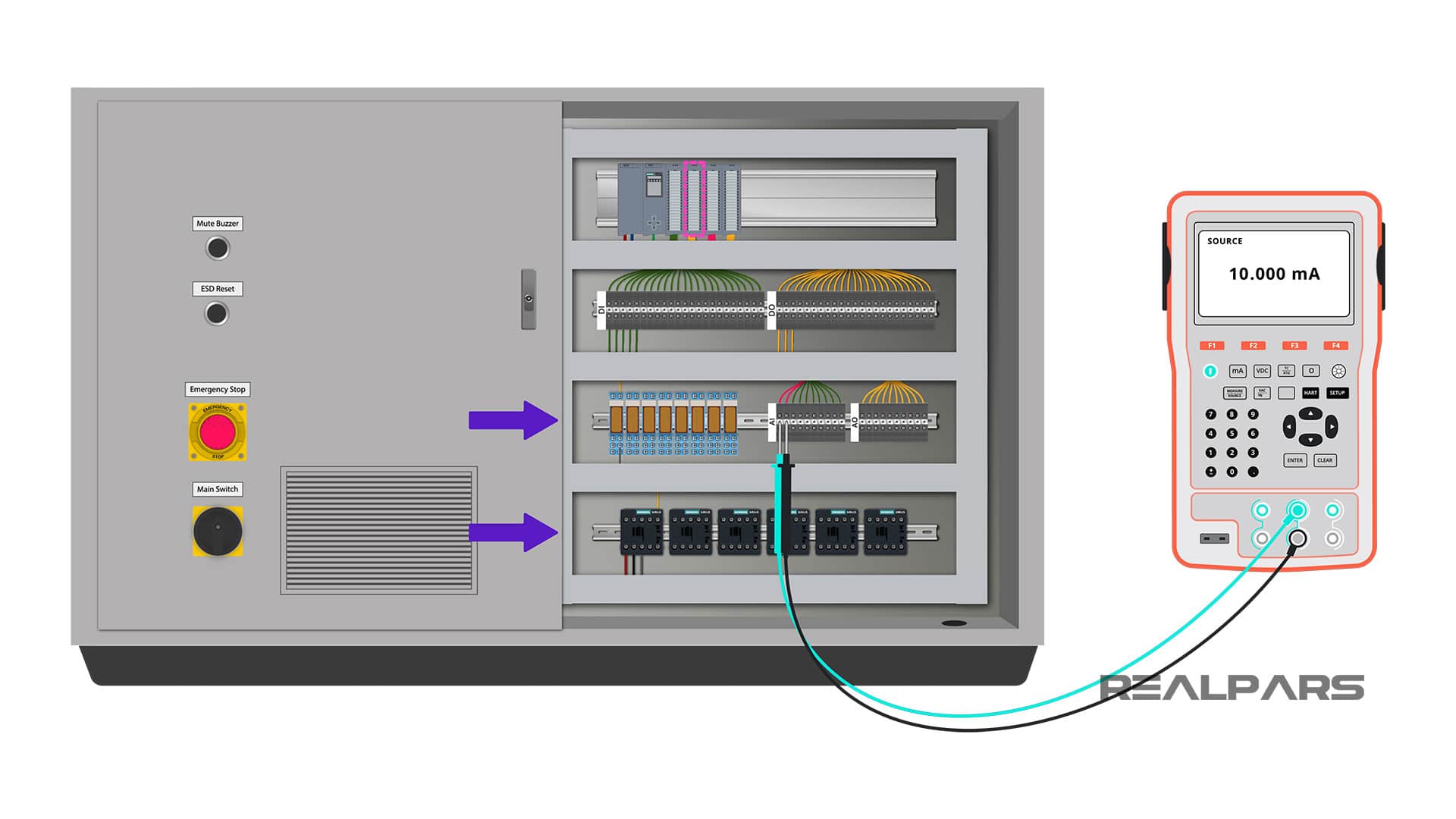
Let’s start with the digital inputs first. The PLC digital inputs are connected to the upside of the terminals highlighted in our control panel example below. The other side of the terminals will be connected to the switches and sensors once we take the cabinet to the site.
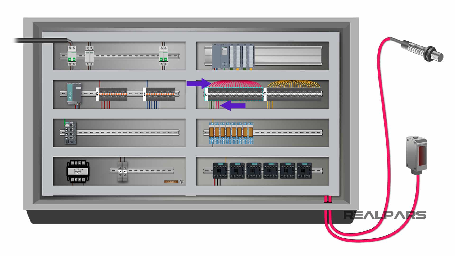
But here since we have some switches on the control cabinet door such as mute buzzer, ESD Reset and Emergency Stop, we have already wired these input devices to the other side of the terminals and we already have them connected to the relevant PLC digital inputs. Let’s start our test with these switches first.
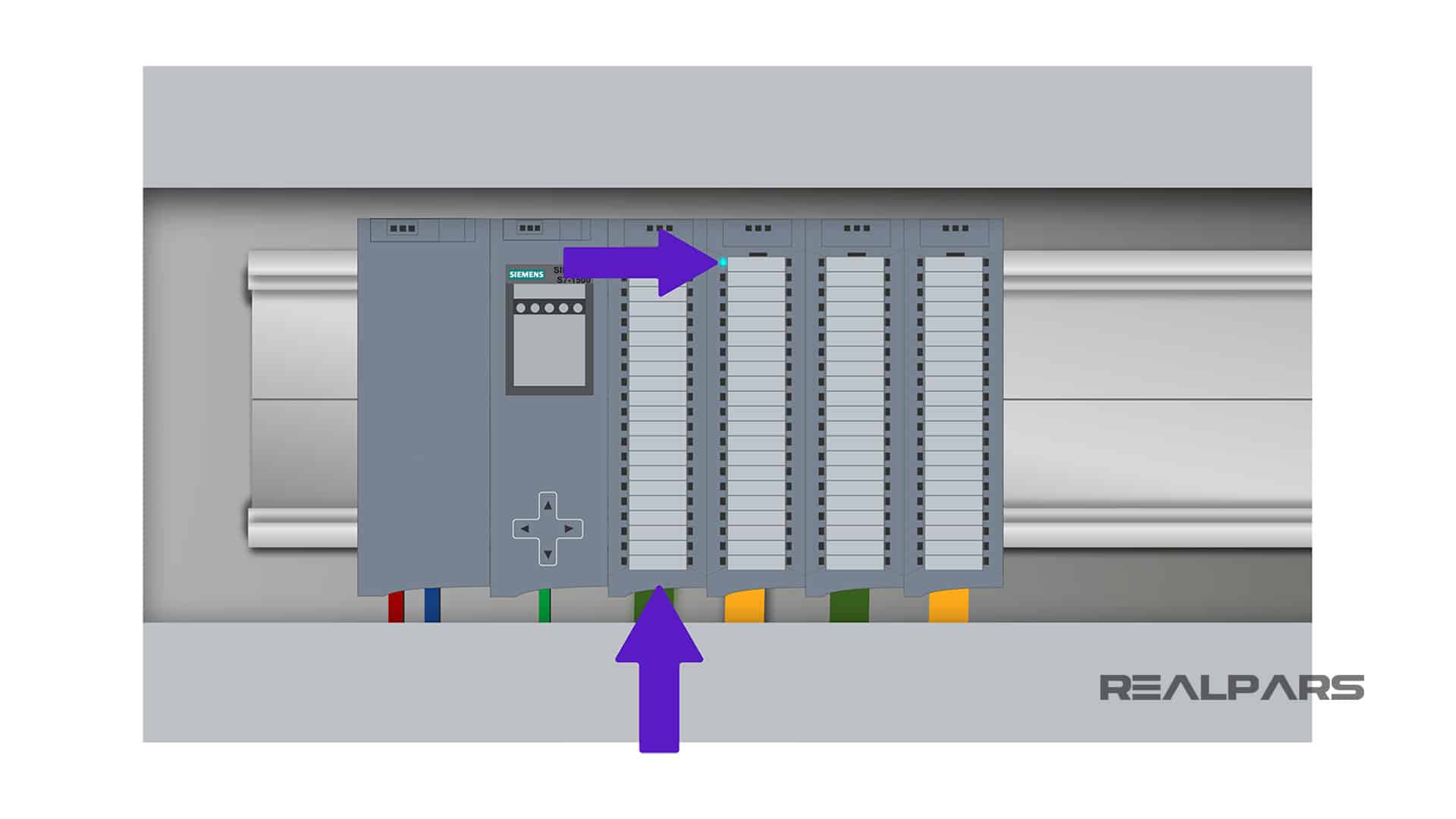
We’ll start with the mute buzzer input. Let’s say that this push button is connected to the first digital input of the PLC. To test this input, all you need to do is to press the push button and see if the LED light for the first digital input on the card turns on.
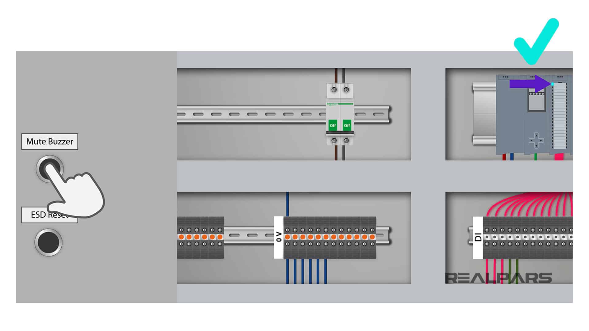
If the LED does not turn on when you press the push button, it means that there is something wrong with the wiring.
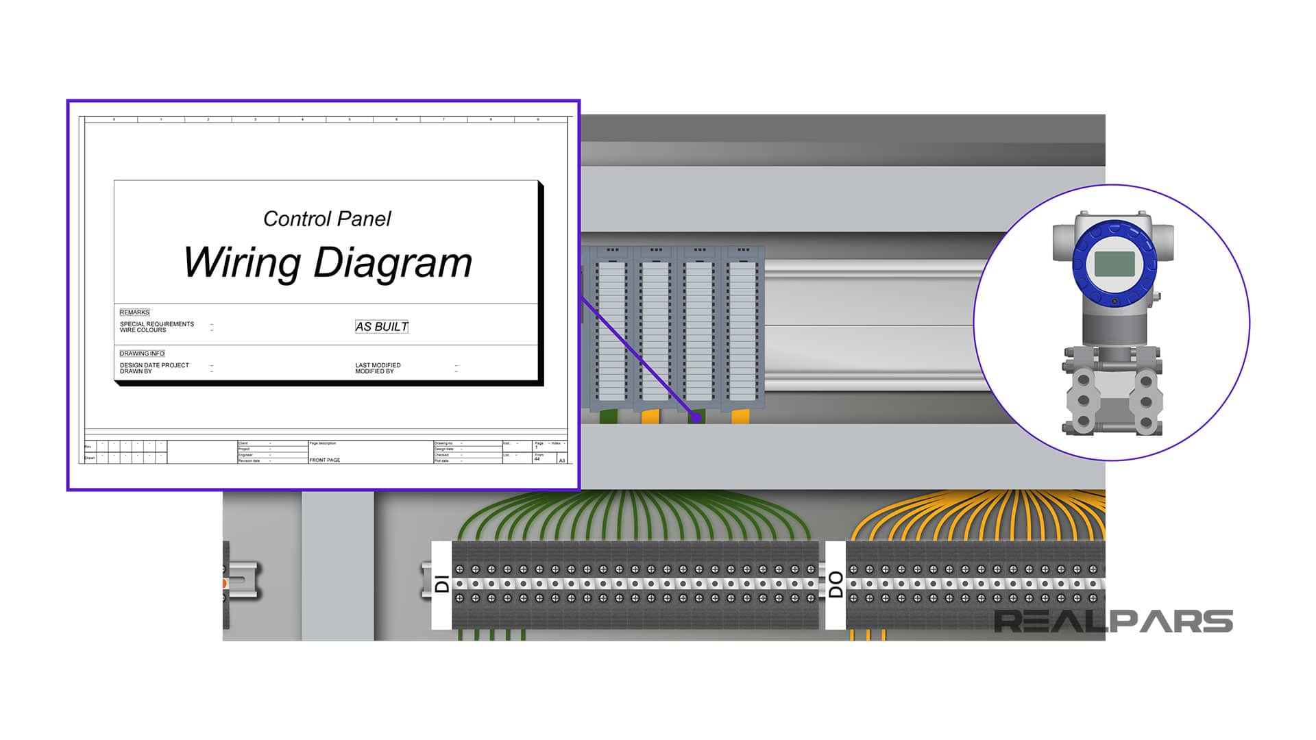
In this case, you need to take the panel wiring diagram and follow the wiring on the panel and fix the issue.
If you don’t know how to read and follow a PLC wiring diagram, you can read a previous RealPars article on this topic, How to Follow an Electrical Panel Wiring Diagram.
Ok… moving on to test the rest of the PLC digital inputs, if the device that will be connected to the digital input is passive, like a simple switch, you can simulate the signal by connecting a piece of wire to the terminal blocks.
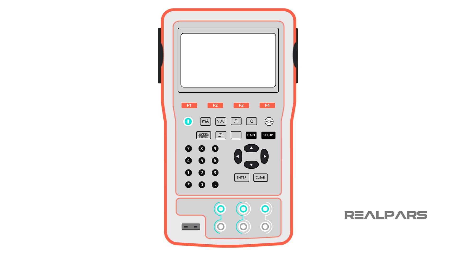
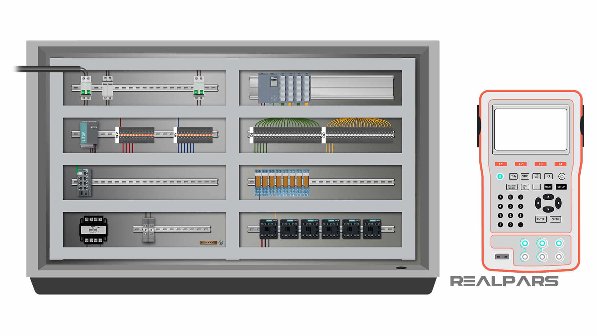
However, if the device is active, you need to look at the wiring diagram and find the best way to simulate the signal coming from that active device. In most cases, you can make use of a simulator. A simulator is a device like this that can accurately reproduce a sensor output.
So if the device that will be connected to the PLC digital input is passive, meaning there is no external power required for the device, you can simulate that using only a piece of wire. If the device is active, you can make use of a simulator to simulate the input signal.
Step 4) Test the PLC digital outputs
After you’re done with testing the digital inputs, you can move on to testing the digital outputs. The digital output card that we have sends a 24-volt signal to various devices connected to individual output terminals.
A digital output could be connected directly to an output device like a buzzer or a relay that could operate an actuator like a motor.
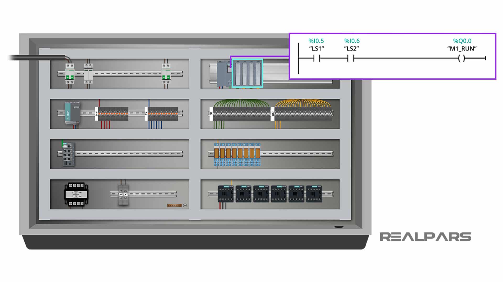
To test each output we just need to give the PLC an input signal and see if the digital outputs change as expected based on the PLC program.
For example, let’s say that the first digital output that we have here is connected to a motor via a contactor. The PLC program logic, says when the level switch 1 and level switch 2 are both active, we need to have the motor connected to this output turned on.
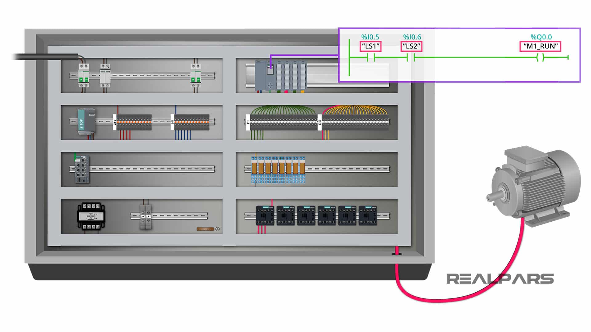
To test the output, all you need to do is to activate the inputs using simulated signals and see if the contactor on the output will be energized.
If the contactor is energized when you do this, it means all the wiring and the PLC logic works perfectly fine for this output. If not, you need to review your wiring using the wiring diagram. You can do the same to test the rest of the PLC digital outputs.
PLC Analog I/O Test
Step 5) Test the PLC analog inputs
As for the next step you need to test the analog inputs. To do this, you simply need to know the type of input signal that will be connected to your PLC analog input.
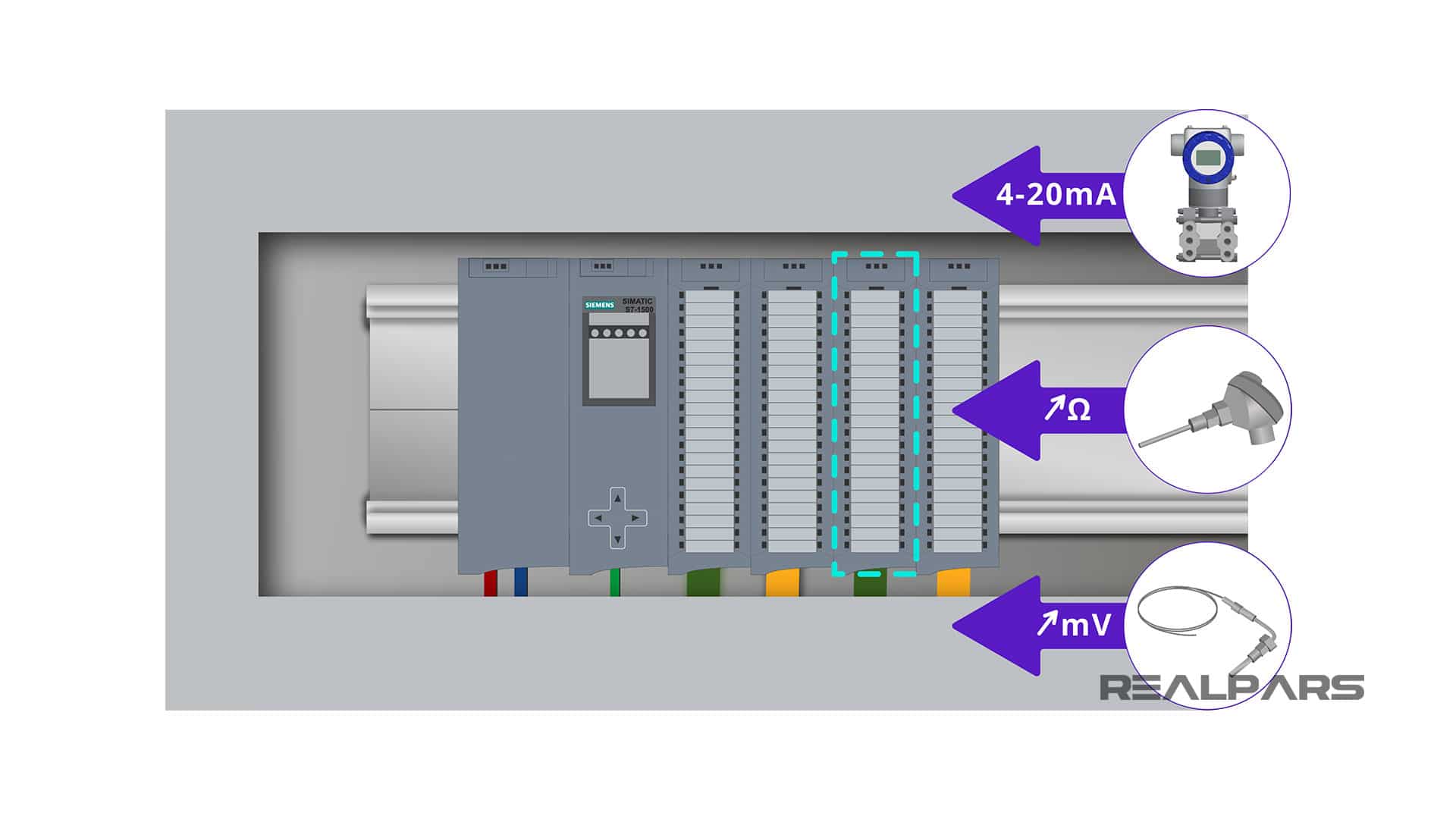
Typical input analog devices are transmitters, RTDs, and thermocouples, each providing different signals to the PLC.
Transmitters typically send a 4-20mA signal, RTDs produce a variable resistance, and Thermocouples produce a very small millivolt signal.
To test the analog input card and wiring in your control panel, you need two things:
1. A signal simulator
2. The wiring diagram of the control panel
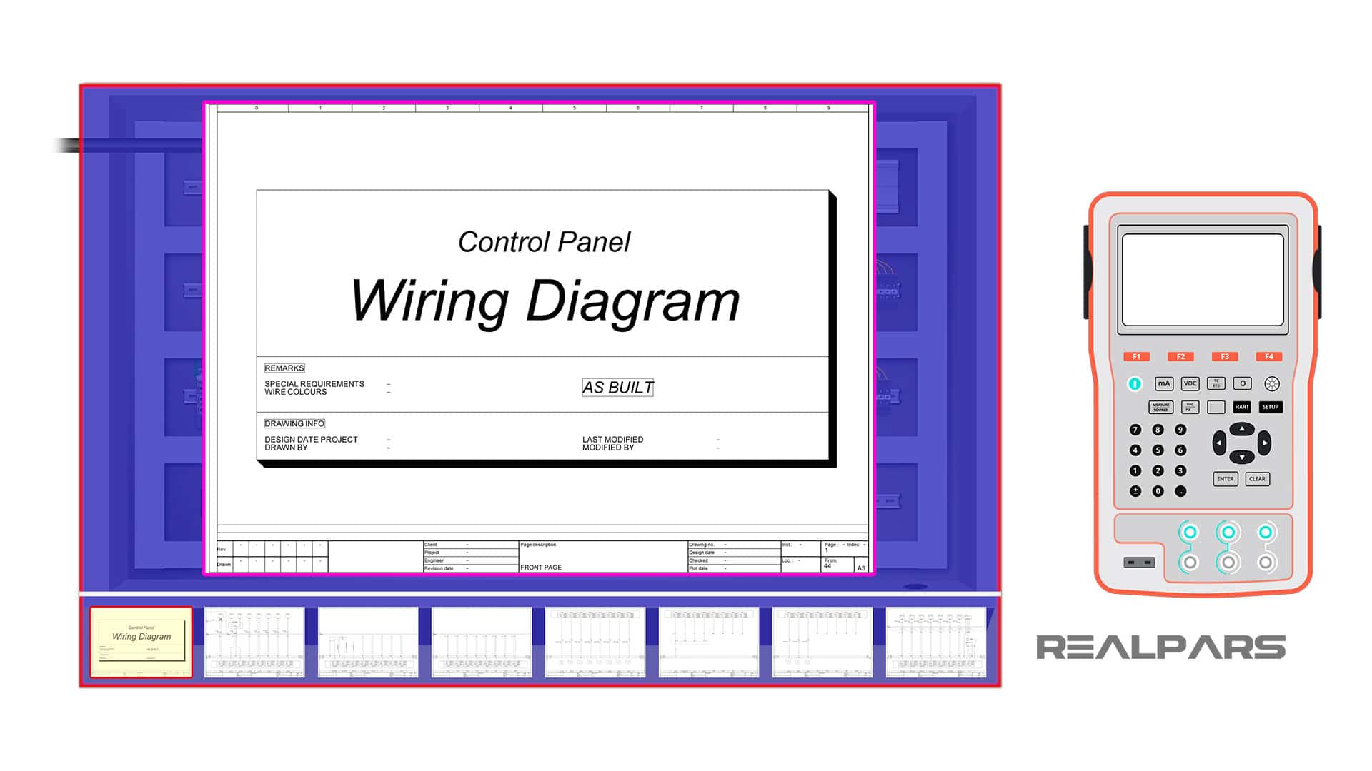
Signal simulator
Simulators are capable of giving you signals that are produced by transmitters, RTDs, and Thermocouples.
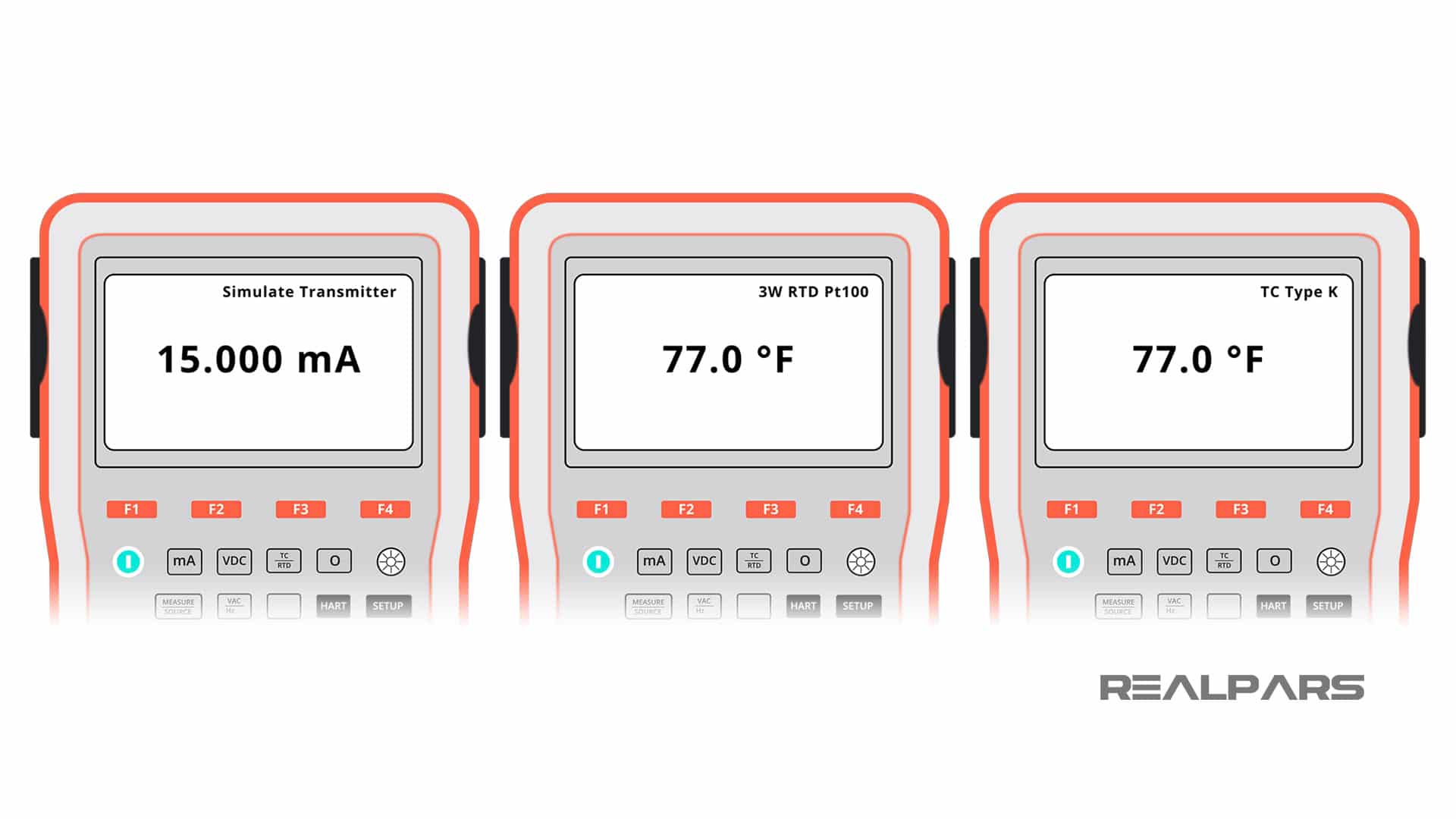
For example, let’s say that our analog input card will receive 4-20 mA input signals from transmitters installed in the field.
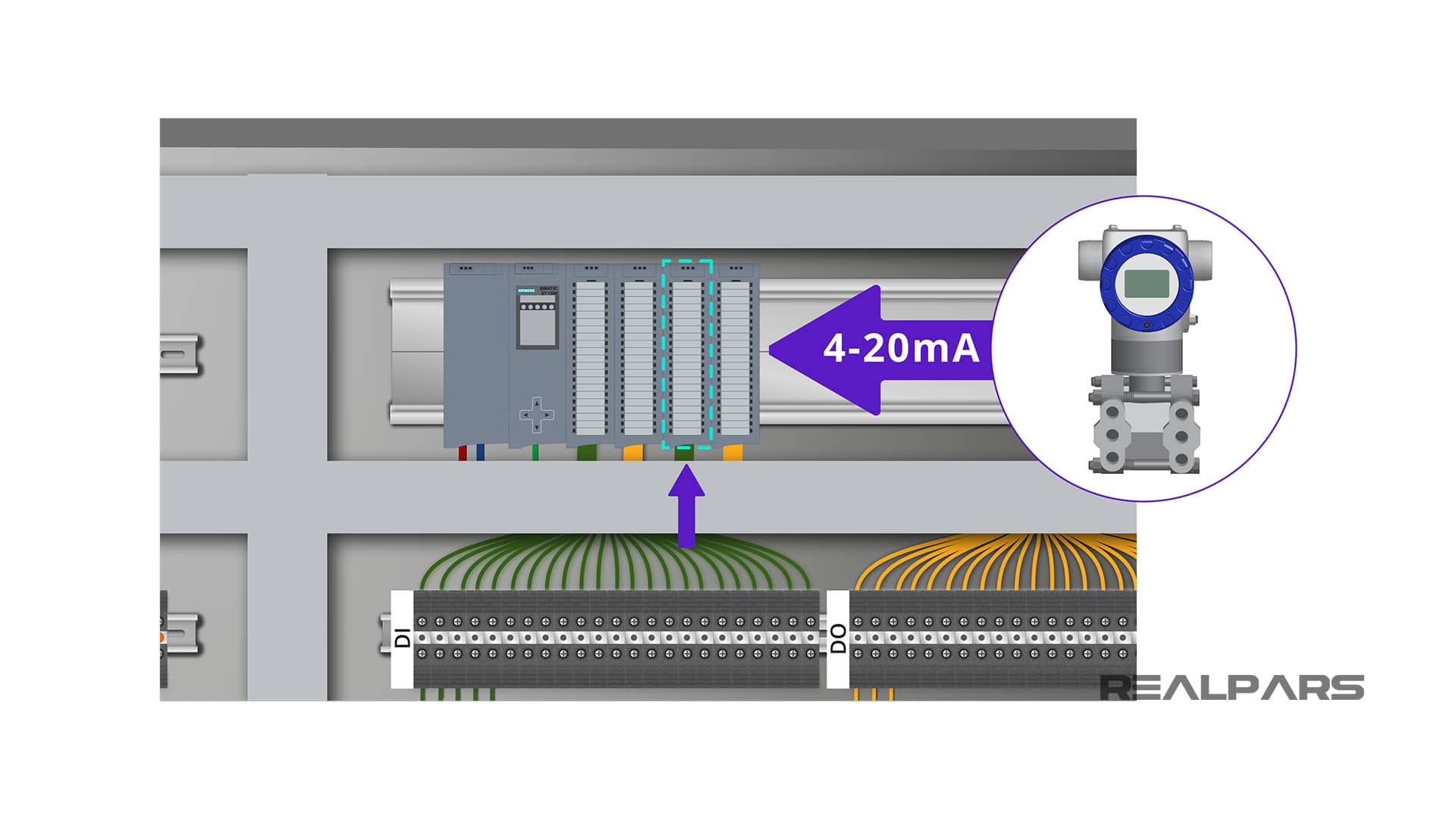
To test this input we first need to know how the transmitters are connected to the card. This is what you should already have on your wiring diagram.
The other way to check the wiring diagram for your card is the manual. For example, this is the wiring diagram for the analog input card that I have installed in my control panel.
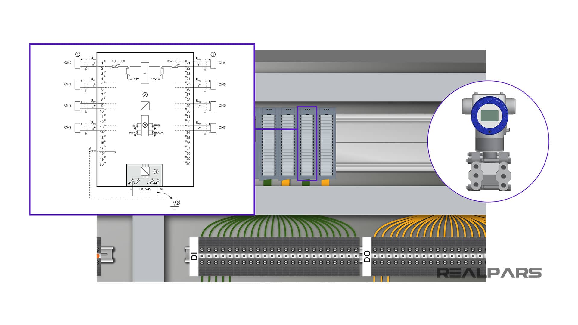
Don’t let all these elements that you see below confuse you. All you need to know here is that if you want to wire a 2-wire transmitter to this card you simply need to connect the positive to terminal number 1 and the negative to the next terminal. The wiring is the same for the rest of the 2-wire transmitters.
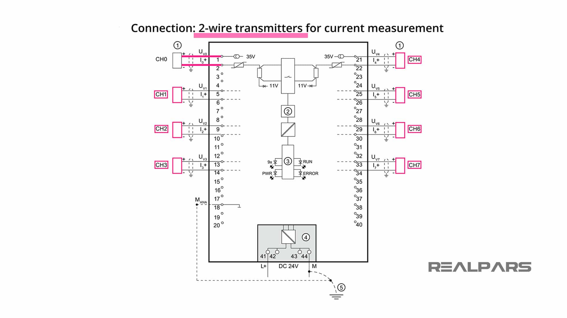
Assuming that other ends of these terminals here are connected to terminals number 1 and 2, to test this input I can put the signal simulator on the 4-20mA current mode and then connect it to the other end of these terminals.
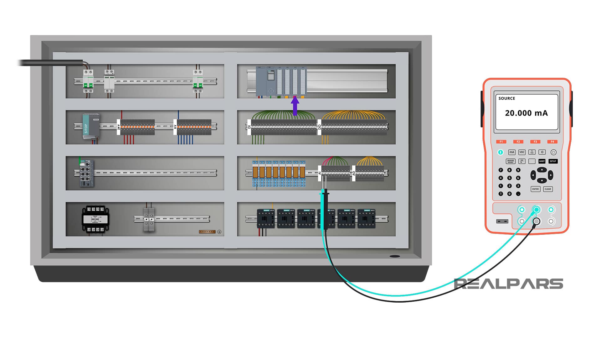
By doing this, I am simulating a 2-wire transmitter connected to my analog input card. Now I can play with the simulator, change the input values and observe the changes on the output based on the PLC logic.
For example, let’s say that this is a pressure transmitter that is used to measure the oil pressure in the system. Based on the PLC logic, if the oil pressure goes under a certain level the oil pump needs to turn on.
To test this I can change the current and look at the HMI installed on the panel to see if the indicator for the oil pump turns on.
If the pump turns on it means that everything works fine for this input and the logic. If the oil pump does not turn on, I need to look into the wiring or my PLC logic.
Now you may ask, what If I don’t have an HMI installed with my panel? How can I see the change in the output? Well, that is also very easy.
To check if the pump turns on in the output, you just need to know to which digital output the pump will be connected to and then you can see if the relay or the contactor will be energized as you change the input current.
So that’s how easy it is to test the analog input card. You can repeat the same process for all of the other inputs as well.
If you are a bit unclear about the wiring of the analog input card make sure to watch this 2-part video series titled how to wire sensors to a PLC. Here are the links:
– How to Wire Sensors to a PLC – Part 1
– How to Wire Sensors to a PLC – Part 2
I promise all of your doubts will be gone after watching these videos.
Step 6) Test the PLC analog outputs
Ok, the last step is to test the analog output card. The testing process here is pretty similar to what we did for the digital output card.
For each analog output we can simulate a signal in the input and then check if the analog output changes based on what we expect in the PLC logic.
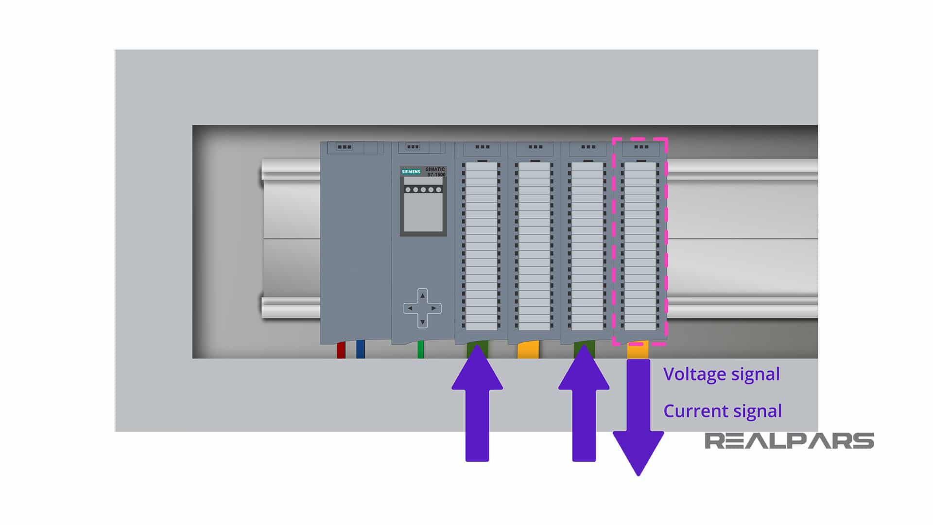
An analog output signal could be either voltage or current. We can measure this using a simple digital multimeter as well.
Most of the signal simulators can also be used to perform measurement functions similar to a digital multimeter.
Ok, so this is pretty much what you need to know to be able to perform a Factory Acceptance Test for your control panel.
Summary
To wrap things up, with the Factory Acceptance Test you simply make sure that all of the PLC inputs and outputs, the wiring, and the PLC logic work as expected before you ship it to the client’s site.
If you have any previous experience performing Factory Acceptance Test as an automaton engineer let us know in the comments below. I guess there are many interesting stories about this that are interesting to read.
Got a friend, client, or colleague who could use some of this information? Please share this article.